Data for EN ISO 13849-1
- Performance Level "d"
- MTTF
d
(Mean Time To Dangerous Failure): 24816
years
- DC (Diagnostic Coverage): 99%
- Category 3
- Lifetime 20 years
Data for EN IEC 62061, EN IEC 61508, EN IEC 61800-5-2
- SIL 2 Capability, SILCL 2
- PFH (Probability of Dangerous failure per
Hour)=7e-10FIT=7e-19/h
- SFF (Safe Failure Fraction) >99%
- HFT (Hardware Fault Tolerance)=0 (1001
architecture)
- Lifetime 20 years
Data for EN IEC 61508 low demand
- PFDavg for one year proof test: 3, 07E-14
- PFDavg for three year proof test: 9, 20E-14
- PFDavg for five year proof test: 1, 53E-13
SISTEMA Data
Functional safety data is available via a data library for use
with the SISTEMA calculation tool from the IFA (Institute
for Occupational Safety and Health of the German Social
Accident Insurance), and data for manual calculation. The
library is permanently completed and extended.
Abbrev. Ref. Description
Cat. EN 954-1 Category, level “B, 1-4”
FIT Failure In Time: 1E-9 hours
HFT IEC 61508 Hardware Fault Tolerance: HFT = n
means, that n+1 faults could cause a
loss of the safety function
MTTFd EN ISO
13849-1
Mean Time To Failure - dangerous. Unit:
years
PFH IEC 61508 Probability of Dangerous Failures per
Hour. Consider the PFH value when the
safety device is operated in high
demand (more often than once per
year); or operated in continuous mode,
where the frequency of demands for
operation made on a safety-related
system is greater than one per year.
PL EN ISO
13849-1
Discrete level used to specify the ability
of safety-related parts of control systems
to perform a safety function under
foreseeable conditions. Levels a-e.
SFF IEC 61508 Safe Failure Fraction [%]; Percentage
part of safe failures and dangerous
detected failures of a safety function or
a subsystem related to all failures.
SIL IEC 61508 Safety Integrity Level
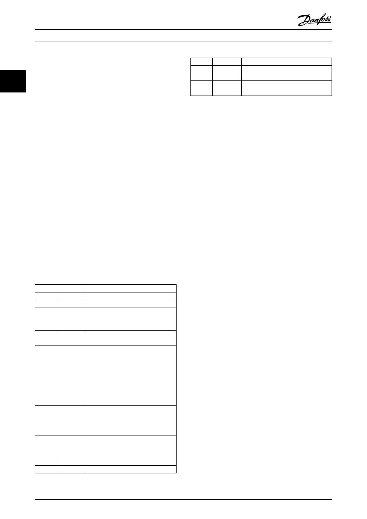
Abbrev. Ref. Description
STO EN
61800-5-2
Safe Torque Off
SS1 EN 61800
-5-2
Safe Stop 1
Table 2.3 Abbreviations Related to Functional Safety
The PFD
avg
value (Probability of Failure on Demand)
Failure probability in the event of a request of the safety
function.
2.2.1 Terminal 37 Safe Stop Function
The frequency converter is available with safe stop
functionality via control terminal 37. Safe stop disables the
control voltage of the power semiconductors of the
frequency converter output stage. This in turn prevents
generating the voltage required to rotate the motor. When
the Safe Stop (T37) is activated, the frequency converter
issues an alarm, trips the unit, and coasts the motor to a
stop. Manual restart is required. The safe stop function can
be used as an emergency stop for the frequency converter.
In normal operating mode when safe stop is not required,
use the regular stop function instead. When automatic
restart is used, ensure the requirements of ISO 12100-2
paragraph 5.3.2.5 are fulfilled.
Liability Conditions
It is the responsibility of the user to ensure that qualified
personnel installs and operates the safe stop function:
•
Read and understand the safety regulations
concerning health and safety/accident prevention
•
Understand the generic and safety guidelines
given in this description and the extended
description in the Design Guide
•
Have a good knowledge of the generic and safety
standards applicable to the specific application
User is defined as: integrator, operator, service technician,
maintenance technician.
Standards
Use of safe stop on terminal 37 requires that the user
satisfies all provisions for safety including relevant laws,
regulations and guidelines. The optional safe stop function
complies with the following standards.
•
EN 954-1: 1996 Category 3
•
IEC 60204-1: 2005 category 0 – uncontrolled stop
•
IEC 61508: 1998 SIL2
•
IEC 61800-5-2: 2007 – safe torque off (STO)
function
•
IEC 62061: 2005 SIL CL2
Safety Instructions and Gen...
Operating Instructions VLT
®
CDS302 and CDS303
8 MG34M302 - VLT
®
is a registered Danfoss trademark/Commercial Compressor
22


