Page is loading ...

INSTRUCTIONS
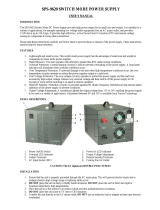
8510233P01-A © Danfoss Commercial Compressors - September 2006

2
8510233P01-A © Danfoss Commercial Compressors - September 2006
Instructions
PART I: INSTALLATION MANUAL ....3
Safety instructions and General Warning ............4
Disposal ...................................................................4
Caution ....................................................................4
CD302 Operating Instructions Software
version: 1.0x ...........................................................4
High Voltage Warning ........................................4
Safety Instructions ...............................................4
General warning ...................................................4
Leakage Current ...................................................4
Residual Current Device ....................................4
IT Mains ...................................................................4
Before Commencing Repair Work ..................4
Avoid Unintended Start .....................................4
Safe Stop of CD 302.............................................4
General Specications ...............................................4
Mains supply (L1, L2, L3) ...................................4
Motor compressor output (U, V, W) ...............4
Digital inputs .........................................................4
Safe stop Terminal 37 .........................................4
Analog inputs ........................................................5
Digital output ........................................................5
Analog output .......................................................5
Control card, 24 V DC output ...........................5
Control card, 10 V DC output ...........................5
Control card, RS 485 serial communication 5
Control card, USB serial communication .....5
Relay outputs ........................................................5
How to install .................................................................5
Mechanical Installation ......................................5
Mechanical mounting ........................................5
Safety Requirements of Mechanical Instal-
lation ........................................................................5
Mechanical Dimension ......................................6
Electrical installation...........................................7
Commissionning & nal tests ............................... 14
Final Set-Up and Test ....................................... 14
Safe Stop Commissioning Test ..................... 14
High Voltage Test .............................................. 14
Trouble shooting ....................................................... 15
PART II:PROGRAM MANUAL . 17
How to Program on the Graphical Local .......... 18
Control Panel ...................................................... 18
Display lines ........................................................ 18
Display Contrast Adjustment ....................... 18
Indicator lights (LEDs) ..................................... 18
LCP keys ........................................................................ 18
Open loop control method .................................... 18
Controls using an external controller with
0-10V signal ....................................................... 18
Controls using an external controller with
0-10V signal ........................................................ 18
Quick setup ....................................................... 18
Open Loop with external reference ........... 18
Controls using a 4-20mA process signal
& CD302-PID controller ................................... 19
Controls using a 4-20mA process signal
& CD302-PID controller + Smart Logic Control 19
Navigation Keys ................................................. 19
Quick Transfer of Parameter Settings ........ 19
Data storage in LCP .......................................... 19
Data transfer from LCP to drive.................... 19
Intialisation to Default Settings ................... 19
Parameter Selection ................................................. 20
Changing Data ........................................................... 20
Changing a Text Value ............................................. 20
Changing a Group of Numeric Data Values ..... 20
Parameter setup modications ............................ 20
Parameters: Operation and Display .................... 20
0-0* Basic Settings ............................................ 20
0-2* LCP Display ................................................ 20
0-4* LCP Keypad ................................................ 21
0-5* Copy / Save ................................................ 21
0-6* Password..................................................... 21
Parameters: Load and Motor ................................. 21
1-0* General Settings ...................................... 21
1-2* Motor Data ................................................. 21
1-3* Adv. Motor Data ....................................... 22
1-6* Load Depend. Setting ............................ 22
1-7* Start Adjustments ................................... 22
1-8* Stop Adjustments .................................... 22
1-9* Motor Temperature ................................. 22
Parameters: Reference/Ramps .............................. 22
3-0* Reference Limits ...................................... 22
Parameters: Limits/Warnings ................................ 23
4-1* Motor Limits .............................................. 23
4-5* Adj. Warnings ............................................ 23
Parameters: Digital In/Out...................................... 23
5-0* Digital In/Out Mode ............................... 23
5-1* Digital Inputs ............................................ 23
Parameters: Analog In/Out .................................... 23
6-0* Analog In/Out Mode .............................. 23
6-1* Analog Input 1 .......................................... 23
Parameters: Controllers ........................................... 24
7-0* Speed PID Ctrl. .......................................... 24
7-2* Process Ctrl. Feedb. ................................. 24
Parameters: Special Functions .............................. 24
14-0* Inverter Switching ................................ 24
14-1* Mains On/O .......................................... 24
14-2* Trip Reset .................................................. 24
Parameters: Smart Logic Control ......................... 25
Quick Set-up for VTZ Compressor Drive ... 26
PID Closed Loop menu for VTZ Compres-
sor Drive ............................................................... 27
Factory set-up for Commun Parameters .. 28
Compressor specic parameters for code
G R404A/R407C ................................................. 29
Compressor specic parameters for code
J R404A/R407C ................................................... 30
Compressor specic parameters for code
G R134a ................................................................ 31

3
8510233P01-A © Danfoss Commercial Compressors - September 2006
Instructions
PART I:
Installation
Manual

4
8510233P01-A © Danfoss Commercial Compressors - September 2006
Instructions
Safety instructions and General Warning
Disposal
Drive:
Equipment containing electrical com-
ponents may not be disposed together
with domestic waste.
It must be separate collected with Electrical and
Electronic Waste according to local and currently
valid legislation.
Compressors:
Danfoss recommends not to thriw away a used
compressor but to a dispose of the compressor
and its oil at a specialised recycling company site
Caution
The CD 302 Compressor Drive™ DC link
capacitors remain charged after power
has been disconnected. To avoid an
electrical shock hazard, disconnect the CD 302
from the mains before carrying out maintenance.
Wait at least as follows before doing service on
the frequency converter:
CD 302: ≤ 7.5 kW 4 minutes
CD 302: 11 . 22 kW 15 minutes
Be aware that there may be high voltage on the DC
link even when the LEDs are turned o.
CD302 Operating Instructions Software ver-
sion: 1.0x
These Operating Instructions can be used for all CD302
Compressor Drives™ with software version 1.0x.
The software version number can be seen from
parameter 15-43.
High Voltage Warning
The voltage of the CD 302 is dangerous
whenever the converter is connected
to mains.
Incorrect tting of the motor or frequency converter
may cause damage to the equipment, serious injury
or death. Consequently, it is essential to comply with
the instructions in this manual as well as local and
national rules and safety regulations.
Safety Instructions
. Make sure the CD 302 is properly connected to
earth.
. Do not remove mains plugs or motor plugs
while the CD 302 is connected to mains.
. Protect users against supply voltage.
. Protect the motor against overloading according
to national and local regulations.
. Motor overload protection is included in the
default settings.
. The earth leakage current exceeds 3.5 mA.
. The [OFF] key is not a safety switch. It does not
disconnect the CD 302 from mains.
General warning
Warning:
Touching the electrical parts may be fatal
- even after the equipment has been
disconnected from mains.
Also make sure that other voltage inputs have
been disconnected, such as load-sharing (linkage
of DC intermediate circuit).Using CD 302 Com-
pressor Drives™: wait at least 15 minutes.
Shorter time is allowed only if indicated on the
nameplate for the specic unit.
Leakage Current
The earth leakage current from the
CD 302 exceeds 3.5 mA. To ensure that
the earth cable has a good mechanical
connection to the earth connection (terminal 95),
the cable cross section must be at least 10 mm2 or
2 times rated earth wires terminated separately.
Residual Current Device
This product can cause a D.C. current in the pro-
tective conductor. Where a residual current de-
vice (RCD) is used for extra protection, only an
RCD of Type B (time delayed) shall be used on the
supply side of this product. See also RCD Applica-
tion Note MN.90.GX.02.Protective earthing of the
CD 302 and the use of RCD.s must always follow
national and local regulations.
IT Mains
Do not connect 400 V frequency
converters with RFI-lters to mains sup-
plies with a Voltage between phase and
earth of more than 440 V. For IT mains and delta
earth (grounded leg), mains voltage may exceed
440 V between phase and earth.
Par. 14-50 RFI 1 can on CD 302 be used to discon-
nect the internal RFI capacitors from the RFI lter to
ground. If this is done it will reduce the RFI perfor-
mance to A2 level.
Before Commencing Repair Work
1. Disconnect CD 302 from mains
2. Disconnect DC bus terminals 88 and 89
3. Wait for discharge of the DC-link. See period
of time on the warning label.
4. Remove motor cable
Avoid Unintended Start
While CD 302 is connected to mains, the motor
can be started/stopped using digital commands,
bus commands, references or via the Local
Control Panel (LCP).
. Disconnect the CD 302 from mains whenever
personal safety considerations make it necessary
to avoid unintended start.
. To avoid unintended start, always activate the
[OFF] key before changing parameters.
. An electronic fault, temporary overload, a fault
in the mains supply, or lost motor connection
may cause a stopped motor to start. CD 302 with
Safe Stop provides a certain degree of protection
against such unintended start, if the Safe Stop Ter-
minal 37 is on low voltage level or disconnected.
Safe Stop of CD 302
The CD 302 can perform the safety function Safe
Torque O (As dened by draft CD IEC 61800-5-2)
or Stop Category 0 (as dened in EN 60204-1).
It is designed and approved suitable for the re-
quirements of Safety Category 3 in EN 954-1.
This functionality is called Safe Stop. Prior to in-
tegration and use of Safe Stop in an installation,
a thorough risk analysis on the installation must
be carried out in order to determine whether the
Safe Stop functionality and safety category are
appropriate and sucient. In order to install and
use the Safe Stop function in accordance with
the requirements of Safety Category 3 in EN 954-
1, the related information and instructions of the
CD 302 Design Guide must be followed!
The information and instructions of the Opera-
ting Instructions are not sucient for a correct
and safe use of the Safe Stop functionality!
General Specifications
Mains supply (L1, L2, L3)
• Supply voltage: 200-240 V ±10%
• Supply voltage: 380-480 V ±10%
• Supply voltage: 525-600 V ±10%
• Supply frequency: 50/60 Hz
• Max. imbalance temporary between mains
phases: 3.0 % of rated supply voltage
• True Power Factor (λ): ≥ 0.9 nominal at rated load
• Displacement Power Factor (cos φ) near unity:
(> 0.98)
• Switching on input supply L1, L2, L3 (power-
ups) ≤ 7.5 kW: maximum 2 times/min.
• Switching on input supply L1, L2, L3 (power-
ups) ≥ 11 kW: maximum 1 time/min.
• Environment according to EN60664-1: overvol-
tage category III/pollution degree 2
The unit is suitable for use on a circuit capable of
delivering not more than 100.000 RMS symmetri-
cal Amperes, 240/500/600 V maximum.
Motor compressor output (U, V, W)
• Output voltage: 0 - 100% of supply voltage
• Switching on output: see param number 14-01
in table page 28.
Digital inputs
• Voltage level: 0 - 24 V DC
• Voltage level, logic.0. PNP: < 5 V DC
• Voltage level, logic.1. PNP: > 10 V DC
• Voltage level, logic .0. NPN2): > 19 V DC
• Voltage level, logic .1. NPN2): < 14 V DC
• Maximum voltage on input: 28 V DC
• Input resistance, Ri: approx. 4 kΩ
Safe stop Terminal 37
Terminal 37 is xed PNP logic
• Voltage level: 0 - 24 V DC
• Voltage level, logic.0. PNP: < 4 V DC
• Voltage level, logic.1. PNP: >20 V DC
• Nominal input current at 24 V: 50 mA rms
• Nominal input current at 20 V: 60 mA rms
• Input capacitance: 400 nF
All digital inputs are galvanically isolated from
the supply voltage (PELV) and other high-voltage
terminals.
1) Terminals 27 and 29 can also be programmed
as output.
2) Except safe stop input Terminal 37.
3) Terminal 37 can only be used as safe stop
input.Terminal 37 is suitable for category 3
installations according to EN 954-1 (safe stop
according to category 0 EN 60204-1) as required
by the EU Machinery Directive 98/37/EC. Terminal
37 and the Safe Stop function are designed in
conformance with EN 60204-1, EN 50178, EN
61800-2, EN 61800-3, and EN 954-1. For correct
and safe use of the Safe Stop function follow the
related information and instructions in the Design
Guide.

5
8510233P01-A © Danfoss Commercial Compressors - September 2006
Instructions
Analog inputs
• Number of analog inputs: 2
• Terminal number: 53, 54
• Modes: Voltage or current
• Mode select: Switch S201 and switch S202
• Voltage mode: Switch S201/switch S202 = OFF (U)
• Voltage level: -10 to +10 V (scaleable)
• Input resistance, Ri: approx. 10 kΩ
• Max. voltage: ± 20 V
• Current mode: Switch S201/switch S202 = ON (I)
• Current level: 0/4 to 20 mA (scaleable)
• Input resistance, Ri: approx. 200 Ω
• Max. current: 30 mA
• Resolution for analog inputs: 10 bit (+ sign)
• Accuracy of analog inputs: Max. error 0.5% of full scale
• Bandwidth: 100 Hz
The analog inputs are galvanically isolated from
the supply voltage (PELV) and other high-voltage
terminals.
Digital output
• Programmable digital/pulse outputs: 2
• Terminal number: 27, 29
• Voltage level at digital/frequency output: 0 - 24 V
• Max. output current (sink or source): 40 mA
• Max. load at frequency output: 1 kΩ
• Max. capacitive load at frequency output: 10 nF
• Minimum output frequency at frequency output: 0 Hz
• Maximum output frequency at frequency
output: 32 kHz
• Accuracy of frequency output: Max. error: 0.1 %
of full scale
• Resolution of frequency outputs: 12 bit
1) Terminal 27 and 29 can also be programmed as input.
The digital output is galvanically isolated from the supply
voltage (PELV) and other high-voltage terminals.
Analog output
• Number of programmable analog outputs: 1
• Terminal number: 42
• Current range at analog output: 0/4 - 20 mA
• Max. load to common at analog output: 500 Ω
• Accuracy on analog output: Max. error: 0.5 % of
full scale
• Resolution on analog output: 12 bit
The analog output is galvanically isolated from
the supply voltage (PELV) and other high-voltage
terminals.
Control card, 24 V DC output
• Terminal number: 12, 13
• Max. load: 200 mA
The 24 V DC supply is galvanically isolated from
the supply voltage (PELV), but has the same
potential as the analog and digital inputs and
outputs.
Control card, 10 V DC output
• Terminal number: 50
• Output voltage: 10.5 V ±0.5 V
• Max. load: 15 mA
The 10 V DC supply is galvanically isolated from
the supply voltage (PELV) and other high-voltage
terminals.
Control card, RS 485 serial communication
• Terminal number: 68 (P,TX+, RX+), 69 (N,TX-, RX-)
• Terminal number 61: Common for terminals 68
and 69
The RS 485 serial communication circuit is
functionally separated from other central circuits
and galvanically isolated from the supplier
voltage (PELV).
Control card, USB serial communication
• USB standard: 1.1 (Full speed)
• USB plug: USB type B .device. plug
Connection to PC is carried out via a standard
host/device USB cable.
The USB connection is galvanically isolated from
the supply voltage (PELV) and other high-volta-
ge terminals. The USB ground connection is not
galvanically isolated from protection earth. Use
only isolated laptop as PC connection to the USB
connector on CD 302 drive.
Relay outputs
• Programmable relay outputs: 2
• Relay 01 Terminal number: 1-3 (break),1-2 (make)
• Max. terminal load (AC-1)1) on 1-3 (NC), 1-2 (NO)
(Resistive load): 240 V AC, 2 A
• Max. terminal load (AC-15)1) (Inductive load @
cosφ 0.4): 240 V AC, 0.2 A
• Max. terminal load (DC-1)1) on 1-2 (NO), 1-3 (NC)
(Resistive load): 60 V DC, 1A
• Max. terminal load (DC-13)1) (Inductive load): 24
V DC, 0.1A
• Relay 02 (CD 302 only) Terminal number: 4-6
(break), 4-5 (make)
• Max. terminal load (AC-1)1) on 4-5 (NO) (Resistive
load): 400 V AC, 2 A
• Max. terminal load (AC-15)1) on 4-5 (NO)
(Inductive load @ cosφ 0.4): 240 V AC, 0.2 A
• Max. terminal load (DC-1)1) on 4-5 (NO) (Resistive
load): 80 V DC, 2 A
How to install
Mechanical Installation
Find the following parts included in the CD302
Accessory Bag.
• Accessory Bag ≤ 7.5 kW
•Accessory Bag ≤ 7.5 kW, IP55
• Accessory Bag 11 – 22 kW
Mechanical mounting
1) Drill holes in accordance with the measure-
ments given.
2) You must provide screws suitable for the
surface on which you want to mount the CD 302.
Retighten all four screws.
CD 302 IP20 allows side-by-side installation. Be-
cause of the need for cooling, there must be a
minimum of 100 mm free air passage above and
below the CD 302.
The back wall must always be solid. All CD302 are
equiped of a back metal plate to garantee proper
heat exchanger ventilation. Never remove this
metal sheet.
Safety Requirements of Mechanical Installation
The frequency converter is cooled by means of
air circulation.
To protect the unit from overheating, it must be
ensured that the ambient temperature does not
exceed the maximum temperature stated for the
frequency converter and that the 24-hour ave-
rage temperature is not exceeded. If the ambient
temperature is in the range of 45°C - 55°C, dera-
ting of the frequency converter will become rele-
vant. The service life of the frequency converter
is reduced if derating for ambient temperature is
not taken into account.

6
8510233P01-A © Danfoss Commercial Compressors - September 2006
Instructions
Mechanical Dimension
Mechanical dimensions
Frame size A2 Frame size A3 Frame size A5 Frame size B1 Frame size B2
4.0 kW (380-480 V)
4 kW (525-600 V)
3.0 kW (200-240 V)
5.5 - 7.5 kW (380-480 V)
5.5 - 7.5 kW (525-600 V)
4.0 kW (200-240 V)
4.0 - 7.5 kW (380-480 V)
5.5 - 7.5 kW (200-240 V)
11-15 kW (380-480 V)
11kW (200-240 V)
18.5-22 kW (380-480 V)
IP 20 IP 20 IP 55 IP 21 / IP 55 IP 21 / IP 55
Height
Height of black plate A 268 mm 268 mm 420 mm 480 mm 650 mm
Distance between mounting holes a 257 mm 257 mm 402 mm 454 mm 624 mm
Width
Width of black plate B 90 mm 130 mm 242 mm 242 mm 242 mm
Distance between mounting holes b 70 mm 110 mm 215 mm 210 mm 210 mm
Depth
Depth without option A/B C 205 mm 205 mm 195 mm 260 mm 260 mm
Depth with option A/B C 220 mm 220 mm 195 mm 260 mm 260 mm
Screw holes
c 8.0 mm 8.0 mm 8.25 mm 12 mm 12 mm
d ∅ 11 mm ∅ 11 mm ∅ 12 mm ∅ 19 mm ∅ 19 mm
e ∅ 5.5 mm ∅ 5.5 mm ∅ 6.5 mm ∅ 9 mm ∅ 9 mm
f 9 mm 9 mm 9 mm 9 mm 9 mm
Max weight 4.9 kg 6.6 kg 13.5 kg 23 kg 27 kg

7
8510233P01-A © Danfoss Commercial Compressors - September 2006
Instructions
Electrical installation
Cables general
Always comply with national and local regulations
on cable cross-sections.
Tightening-up Torque
CD
size
Cable for: Tightening
up torque
3-7.5 kW Line, load sharing motor
Compressor cable
1.8 Nm
11-22 kW Line, load sharing motor
compressor cable
1.8 Nm
11-22 kW Motor compressor cable 1.8 Nm
Relay 0.5 - 0.6 Nm
Earth 2 - 3 Nm
• Removal of knockouts for extra cables
- Remove cable entry from the frequency
converter (Avoiding foreign parts in the frequen-
cy converter when removing knockouts)
- Cable entry has to be supported around the
knockout you intend to remove.
- The knockout can now be removed with a
strong mandrel and a hammer.
- Remove burrs from the hole.
- Mount Cable entry on frequency converter.
• Connection to Mains and Earthing
How to connect to mains and earthing (A2 and A3
enclosure).
- Make sure the CD 302 is properly earthed.
Connect to earth connection (terminal 95). Use
screw from the accessory bag.
- Place plug connector 91, 92, 93 from the ac-
cessory bag onto the terminals labelled MAINS at
the bottom of CD302.
- Connect mains wires to the mains plug
connector.
Connection to Mains and Earthing
How to connect to mains and earthing (B1 and B2
enclosure)
• IT Mains
Check that mains voltage corresponds to the
mains voltage of the CD302 name plate.
L1, L2, L3 mains have to be connected preferably
clockwise direction
• Motor compressor connection
Motor compressor cable must be screened / armou-
red. If an unscreened / unarmoured cable is used,
some EMC requirements are not complied with. For
more information, see EMC specications.
- Fasten decoupling plate to the bottom of CD302
with screws and washers from the accessory bag.
- Attach motor compressor cable to terminals
96 (U), 97 (V), 98 (W).
- Connect to earth connection (terminal 99) on de-
coupling plate with screws from the accessory bag.
- Insert terminals 96 (U), 97 (V), 98 (W) and motor
compressor cable to terminals labelled MOTOR.
Fasten screened cable to decoupling plate with
screws and washers from the accessory bag.
U, V, W for motor compressor need to be cloc-
kwise connected. Note that VTZ compressors
can rotate on both directions, but when used in
manifolded sytems all compressors must have
the same rotation direction to avoid vibration
interferences.
≤7.5 kW IP 55
11 - 22 kW IP 21/55
≤7.5 kW IP 20
• Motor compressors cables
Correct dimensioning of motor compressor cable
cross-section and length is described in the ap-
plication manual.
- Use a screened/armoured motor compressor ca-
ble to comply with EMC emission specications.
- Keep the motor compressor cable as short as
possible to reduce the noise level and leakage
currents.
- Connect the motor compressor cable screen
to both the decoupling plate of the CD302 and to
3 Phase
Power
Input
91 (L1)
92 (L2)
93 (L3)
95 PE

8
8510233P01-A © Danfoss Commercial Compressors - September 2006
Instructions
the metal cabinet of the motor compressor.
- Make the screen connections with the largest
possible surface area (cable clamp). This is done by
using the supplied installation devices in the CD302.
• Electrical installation of motor compressor cables
- Screening of cables :
Avoid installation with twisted screen ends
(pigtails). They spoil the screening eect at
higher frequencies. If it is necessary to break the
screen to install a motor compressor isolator or
motor compressor contactor, the screen must be
continued at the lowest possible HF impedance.
- Cable length and cross-section :
The frequency converter has been tested with a
given length of cable and a given cross-section
of that cable. If the cross-section is increased, the
cable capacitance - and thus the leakage current
- may increase, and the cable length must be
reduced correspondingly.
- Switching frequency :
The switching frequency is factory set at 3.5 kHz.
- Aluminium conductors :
Aluminium conductors are not recommended.
Terminals can accept aluminium conductors but
the conductor surface has to be clean and the
oxidation must be removed and sealed by neutral
acid free Vaseline grease before the conductor
is connected. Furthermore, the terminal screw
must be retightened after two days due to the
softness of the aluminium. It is crucial to keep
the connection a gas tight joint, otherwise the
aluminium surface will oxidize again.
• Fuses
- Branch circuit protection:
In order to protect the installation against
electrical and re hazard, all branch circuits in an
installation, switch gear, machines etc., must be
shortcircuit and overcurrent protected according
to the national/international regulations.
- Short circuit protection:
The frequency converter must be protected
against short-circuit to avoid electrical or re
hazard. Danfoss recommends using the fuses
mentioned below to protect service personnel or
other equipment in case of an internal failure in
the drive. The frequency converter provides full
short circuit protection in case of a short-circuit
on the motor compressor output.
- Over current protection:
Provide overload protection to avoid re hazard
due to overheating of the cables in the installa-
tion. The frequency converter is equipped with
an internal over current protection that can be
used for upstream overload protection (UL-appli-
cations excluded). See par. 4-18. Moreover, fuses
or circuit breakers can be used to provide the
over current protection in the installation. Over
current protection must always be carried out ac-
cording to national regulations.
- UL compliance (380-480 V, 525-600 V)
CD 302 Bussmann SIBA
Littel
fuse
Ferraz-
Shawmut
kW Type RK1 Type J Type T Type RK1 Type K1 Type CC Type RK1
4.0 KTS-R20 JKS-20 JJS-20 5017906-020 KLS-R20 ATM-R20 A6K-20R
5.5-7.5 KTS-R30 JKS-30 JJS-30 5012406-32 KLS-R30 ATM-R30 A6K-30R
11.0 KTS-R40 JKS-40 JJS-40 5014006-040 KLS-R40 A6K-40R
15.0 KTS-R50 JKS-50 JJS-50 5014006-50 KLS-R50 A6K-50R
18.0 KTS-R60 JKS-60 JJS-60 5014006-63 KLS-R60 A6K-60R
22.0 KTS-R80 JKS-80 JJS-80 100 KLS-R80 KLS-R80 A6K-80R
- Non UL compliance :
If UL/cUL is not to be complied with, we recommend
using the following fuses, which will ensure com-
pliance with EN50178.In case of malfunction, not
following the recommendation may result in unne-
cessary damage of the frequency converter.
CD 302
Max. fuse
size
Voltage Type
3K0-3K7 32A* 200-240 V type gG
3K0-4K0 20A* 380-480 V type gG
5K5-7K5 32A* 380-480 V type gG
11K 63A* 380-480 V type gG
15K 63A* 380-480 V type gG
18K 63A* 380-480 V type gG
22K 80A* 380-480 V type gG
* : Max. fuses - see national/ international regulations
for selecting an applicable fuse size.
• Electrical motor compressor protection
The electrical motor compressor protection is fully
provided by the CD302 frequency converter.
- CD302 makes through an Electronic current
measurement anti-overload and lock-rotor mo-
tor compressor protection (see description in the
application manual).
- The frequency converter is protected against
short-circuits on compressor terminals U, V, W.
- If a mains phase is missing, the frequency
converter trips or issues a warning (depending on
the load).
- If a motor compressor phase is missing, the
frequency converter trips.
- The frequency converter is protected against
earth faults on compressor terminals U, V, W.
- The frequency converter is protected against
short circuits on compressor terminals U, V, W.
- Monitoring of the intermediate circuit voltage
ensures that the frequency converter trips if the in-
termediate circuit voltage is too low or too high.
• Access to Control Terminals
A1, A2 and A3 enclosures
A5, B1 and B2 enclosures
1. 10 pole plug digital I/O
2. 3 pole plug RS485 Bus
3. 6 pole analog I/O
4. USB Connection
130BA012.11
1
4
2
3

9
8510233P01-A © Danfoss Commercial Compressors - September 2006
Instructions
To mount the cable to the terminal:
1. Strip isolation of 9-10 mm
2. Insert a screw driver in the square hole.
3. Insert the cable in the adjacent circular hole.
4. Remove the screw driver. The cable is now
mounted to the terminal.
To remove the cable from the terminal:
1. Insert a screw driver in the square hole.
2. Pull out the cable.
• Basic Wiring Example
1. Mount terminals from the accessory bag to
the front of the CD 302.
2. Connect terminals 18, 27 and 37 to +24 V
(terminal 12/13)
Default settings:
18 = start
27 = coast inverse
37 = safe stop inverse

10
8510233P01-A © Danfoss Commercial Compressors - September 2006
Instructions
Diagram showing all electrical terminals.
Terminal 37 is the input to be used for Safe Stop.
Very long control cables and analog signals may
in rare cases and depending on installation result
in 50/60 Hz earth loops due to noise from mains
supply cables.
If this occurs, you may have to break the screen or in-
sert a 100 nF capacitor between screen and chassis.
The digital and analog in- and outputs must be
connected separately to the CD302 common
inputs (terminal 20, 55, 39) to avoid ground cur-
rents from both groups to aect other groups.
For example, switching on the digital input may
disturb the analog input signal.
130BA025.17
91 (L1)
92 (L2)
93 (L3)
PE
88 (-)
89 (+)
50 (+10 V OUT)
53 (A IN)
54 (A IN)
55 (COM A IN)
0/4-20 mA
12 (+24V OUT)
13 (+24V OUT)
37 (D IN)
18 (D IN)
20
(COM D IN)
10Vdc
15mA 130/200mA
+ - + -
(U) 96
(V) 97
(W) 98
(PE) 99
(COM A OUT) 39
(A OUT) 42
(P RS-485) 68
(N RS-485) 69
(COM RS-485) 61
0V
5V
S801
0/4-20 mA
RS-485
RS-485
03
+10Vdc
-10Vdc -
+10Vdc
+10Vdc
0/4-20 mA
-10Vdc -
240Vac, 2A
24Vdc
02
01
05
04
06
240Vac, 2A
24V (NPN)
0V (PNP)
0V (PNP)
24V (NPN)
19 (D IN)
24V (NPN)
0V (PNP)
27
24V
0V
(D IN/OUT)
0V (PNP)
24V (NPN)
(D IN/OUT)
0V
24V
29
24V (NPN)
0V (PNP)
0V (PNP)
24V (NPN)
33 (D IN)
32 (D IN)
1 2
ON
S201
ON
21
S202
ON/I=0-20mA
OFF/U=0-10V
95
400Vac, 2A
P 5-00
21
ON
S801
(R+) 82
(R-) 81
*
*
*
3 Phase
power
input
DC bus
Switch Mode
Power Supply
Motor
Analog Output
Interface
relay1
relay2
(PNP) = Source
(NPN) = Sink
ON=Terminated
OFF=Open
Brake
resistor

11
8510233P01-A © Danfoss Commercial Compressors - September 2006
Instructions
- Control cables must be screened/armoured.
Use a clamp from the accessory bag to connect
the screen to the CD 302 decoupling plate for
control cables.
Generally speaking, control cables must be brai-
ded screened/armoured and the screen must be
connected by means of a cable clamp at both
ends to the metal cabinet of the unit.
The drawing indicates how correct earthing is
carried out and what to do if in doubt.
a. Correct earthing
Control cables and cables for serial communica-
tion must be tted with cable clamps at both ends
to ensure the best possible electrical contact.
b. Wrong earthing
Do not use twisted cable ends (pigtails). They in-
crease the screen impedance at high frequencies.
c. Protection with respect to earth potential between
PLC(Program Logic Controller) and CD 302
If the earth potential between the frequency
converter and the PLC (etc.) is dierent, electric
noise may occur that will disturb the entire sys-
tem. Solve this problem by tting an equalising
cable, next to the control cable. Minimum cable
cross-section: 16mm2.
d. For 50/60 Hz earth loops
If very long control cables are used, 50/60 Hz
earth loops may occur. Solve this problem by
connecting one end of the screen to earth via a
100nF capacitor (keeping leads short).
e. Cables for serial communication
Eliminate low-frequency noise currents between
two frequency converters by connecting one
end of the screen to terminal 61. This terminal
is connected to earth via an internal RC link. Use
twisted-pair cables to reduce the dierential
mode interference between the conductors.
• Safe Stop Installation
To carry out an installation of a Category 0 Stop
(EN60204) in conformance with Safety Category
3 (EN954-1), follow these instructions:
1. The bridge (jumper) between Terminal 37
and 24 V DC of CD 302 must be removed. Cutting
or breaking the jumper is not sucient. Remove
it entirely to avoid short-circuiting. See jumper
on illustration.
2. Connect terminal 37 to 24 V DC by a short-
circuit protected cable. The 24 V DC voltage
supply must be interruptible by an EN954-1 Ca-
tegory 3 circuit interrupt device. If the interrupt
device and the frequency converter are placed in
the same installation panel, you can use a regular
cable instead of a protected one.
• Electrical Installation - EMC protection
The following is a guideline to good engineering
practice when installing frequency converters.
Follow these guidelines to comply with EN
61800-3 First environment. If the installation is
in EN 61800-3 Second environment, i.e. indus-
trial networks, or in an installation with its own
transformer, deviation from these guidelines is
allowed but not recommended. See also paragra-
phs CE Labelling, General Aspects of EMC Emis-
sion and EMC Test Results.
Good engineering practice to ensure EMC-correct
electrical installation:
- Use only braided screened/armoured motor
compressor cables and braided screened/armou-
red control cables. The screen should provide a
minimum coverage of 80%. The screen material
must be metal, not limited to but typically cop-
per, aluminium, steel or lead. There are no special
requirements for the mains cable.
- Installations using rigid metal conduits are not
required to use screened cable, but the motor
compressor cable must be installed in conduit
separate from the control and mains cables. Full
connection of the conduit from the drive to the
motor compressor is required. The EMC perfor-
mance of exible conduits varies a lot and infor-
mation from the manufacturer must be obtained.
- Connect the screen/armour/conduit to earth at
both ends for motor compressor cables as well as
for control cables.
In some cases, it is not possible to connect the
screen in both ends. If so, connect the screen at
the frequency converter. See also Earthing of
Braided Screened/Armoured Control Cables.
- Avoid terminating the screen/armour with twis-
ted ends (pigtails). It increases the high frequency
impedance of the screen, which reduces its eec-
tiveness at high frequencies. Use low impedance
cable clamps or EMC cable glands instead.
- Avoid using unscreened/unarmoured motor
compressor or control cables inside cabinets hou-
sing the drive(s), whenever this can be avoided.
Leave the screen as close to the connectors as
possible.
The illustration shows an example of an EMC-
correct electrical installation of an IP 20 frequency
converter.
The frequency converter is tted in an installation
cabinet with an output contactor and connected
to a PLC, which is installed in a separate cabinet.
SPS etc.
SPS etc.
SPS etc.
Min. 16mm
2
Ausgleichskabel
SPS etc.
/TYSK
PE
FC
PE
MONT. AF KABEL. 100% 04 01 20 130BA051.11
130BA051.11
PE PE
FC
PE PE
FC
100nF
PE
FC
69
FC
PE PE
PE
68
61
68
69
FC
PE
a
b
c
d
e

12
8510233P01-A © Danfoss Commercial Compressors - September 2006
Instructions
Other ways of doing the installation may have just
as good an EMC performance, provided the above
guide lines to engineering practice are followed.
If the installation is not carried out according
to the guideline and if unscreened cables and
control wires are used, some emission require-
ments are not complied with, although the im-
munity requirements are fullled. See the para-
graph EMC test results.
• EMC Correct Installation of an IP20 CD302
• Safety earth connection
The frequency converter has a high leakage
current and must be earthed appropriately for
safety reasons acording to EN 50178.
The earth leakage current from the frequency
converter exceeds 3.5 mA. To ensure a good
mechanical connection from the earth cable to
the earth connection (terminal 95), the cable
cross-section must be at least 10 mm2 or 2 rated
earth wires terminated separately.

13
8510233P01-A © Danfoss Commercial Compressors - September 2006
Instructions
Bus
Start
Process Control via an AKS32
12
13
16
17
18
19
20
27
45
50
53
29
32
33
39
37
1
2
3
COM
+10 V
0/4-20 mA
0/4-20 mA
COM
68
69
RS 485
Frequency converter CD302 Compressor Drive
TM
Analog
output
Analog
input
Digital output
to external
fault relay
0 ± 10 V
0 ± 10 V
6
Incorporate security
devices on 27 input
4
5
54
55
61
42
• Basic examples of control connections
Bus
Start
fault relay
12
13
16
17
18
19
20
27
45
50
53
29
32
33
39
37
3
COM
+10 V
0/4-20 mA
0/4-20 mA
COM
68
69
4
5
0 ± 10 V
or 4-20
mA
Open Loop input 0-10V
between 53 → 55
to external
Frequency converter CD302 Compressor Drive
TM
RS 485
Analog
output
Analog
input
6
Incorporate security
devices on 27 input
Digital output
1
2
54
55
61
42
Bus
Start
to external
fault relay
COM
68
69
0 ± 10 V or
4-20 mA
COM
+10 V
0/4-20 mA
0/4-20 mA
RS 485
Frequency converter CD302 Compressor Drive
TM
Analog
output
Analog
input
Digital output
4
5
54
55
61
42
45
50
53
29
32
33
39
37
18
19
20
27
12
13
16
17
Incorporate security
devices on 27 input
6
1
2
3
Process Control via an AKS33

14
8510233P01-A © Danfoss Commercial Compressors - September 2006
Instructions
Commissionning & final tests
Final Set-Up and Test
To test the set-up and ensure that the frequency
converter is running, follow these steps.
Safe Stop Commissioning Test
After installation and before rst operation, per-
form a commissioning test of an installation or
application making use of CD 302 Safe Stop. Mo-
reover, perform the test after each modication
of the installation or application, which the CD
302 Safe Stop is part of.
The commissioning test:
1. Remove the 24 V DC voltage supply to ter-
minal 37 by the interrupt device while the motor
compressor is driven by the CD 302 (i.e. mains
supply is not interrupted). The test step is passed
if the motor compressor reacts with a coast.
2. Then send Reset signal (via Bus, Digital I/O, or
[Reset] key). The test step is passed if the motor
compressor remains in the Safe Stop state.
3. Then reapply 24 V DC to terminal 37. The test
step is passed if the motor compressor remains in
the coasted state.
4. Then send Reset signal (via Bus, Digital I/O, or
[Reset] key). The test step is passed if the motor
compressor gets operational again.
5. The commissioning test is passed if all four
test steps are passed.
High Voltage Test
Carry out a high voltage test by short-circuiting
terminals U, V, W, L1, L2 and L3. Energize by max.
2.15 kV DC for one second between this short-cir-
cuit and the chassis.
NB: When running high voltage tests of the
entire installation, CD302 compressor Drive and
compressor electrical motor compressor test can
be conducted together.
Warning: when conducting an high voltage
test make sure the system is not under vacuum: this
may cause electrical motor compressor failure.
Never apply the high voltage test to the
control circuit.
M
37
5Vdc
FC 302
130BA073.11
12
Control
board
Inverter
Safe
channel
Safety device Cat.3
(Circuit interrupt
device, possbly with
release input)
"Coast"
Short-circuit protected cable
(if not inside installation cabinet)
Door contact
Mains

15
8510233P01-A © Danfoss Commercial Compressors - September 2006
Instructions
Trouble shooting
VTZ Compressor
not working
CD warning
CD Switchs
to alarm
# 12
Torque
limit
# 13
Over
Current
Check VTZ
+ CD302
compatibility
Replace
relevant part
Check motor
Current &
Settings
Control Comp
Working load
Mains shut o
& reset
VTZ blocked
VTZ to be
replaced
Check
oil level
Piping
oil return
Reset &
start
Power
output
from CD302
drive?
Yes No
Check
Alarm #
# 14 # 15 # 30, 31, 32 # 38
Earth Fault
Output side
Short circuit
Output side
Motor phase
missing
Internal
fault
Check motor
cable
Check VTZ
Motor
Correct
the fault
Mains shut-o
before checking
Reset &
Start
Setting
Error(s)
Come back
to factory
settings
Incompatibility
Between
Software &
Additional option
Contact your
Local Danfoss
Check
Alarm #
(continue)

16
8510233P01-A © Danfoss Commercial Compressors - September 2006
Instructions
# 29 # 65
# 68
Drive over
Temperature
Control card
Over temp.
Safe stop
activated
Check 24 V
On 12/13
terminal
Check
Connections
Check external
controls
Reset &
Start
Check
Alarm #
(continue)
Ambiant temp.
Too high
Electrical cabinet
ventilation
Dirt on
CD302 coil
Air by-pass
Or recycled
Missing CD 302
back side
Metal sheet
Turn o power
Reset &
Start
24V
supply to
terminal 37
direct wire
external controls
inserted
Check
Alarm #
(continue)
Speed limit (low)
Automatic restart
after 30 s
Compressor
stopped
Micro network
shortage
Start failed
Minimum speed
not reached after
2sec.
Compressor
stopped
Automatic restart
after 30 s
10 restarts before
blocage
(20 possible)
#49
# 18

17
8510233P01-A © Danfoss Commercial Compressors - September 2006
Instructions
PART II:
Program
Manual

18
8510233P01-A © Danfoss Commercial Compressors - September 2006
1
2
3
4
b
a
c
130BA018.12
Auto
on
Reset
Hand
on
Off
Status
Quick
Menu
Main
Menu
Alarm
Log
B
a
c
k
Cancel
Info
OK
Status
1(0)
1234rpm 10,4A 43,5Hz
Run OK
83,5Hz
On
Alarm
Warn.
Instructions
How to Program on the Graphical Local
Control Panel
The following instructions are valid for the gra-
phical LCP (LCP 102):
The control panel is divided into four functional
groups:
1. Graphical display with Status lines.
2. Menu keys and indicator lights - changing para-
meters and switching between display functions.
3. Navigation keys and indicator lights (LEDs).
4. Operation keys and indicator lights (LEDs). All
data is displayed in a graphical LCP display, which
can show up to ve items of operating data while
displaying [Status].
Display lines
a. Status line:Status messages displaying icons
and graphic.
b. Line 1-2: Operator data lines displaying data
dened or chosen by the user. By pressing the
[Status] key, up to one extra line can be added.
c. Status line: Status messages displaying text.
Display Contrast Adjustment
Press [status] and [ ] for darker display
Press [status] and [ ] for brighter display
Indicator lights (LEDs)
If certain threshold values are exceeded, the
alarm and/or warning LED lights up. A status and
alarm text appear on the control panel.
The on LED is activated when the frequency
converter receives mains voltage.
. Green LED/On: Control section is working.
. Yellow LED/Warn.: Indicates a warning.
. Flashing Red LED/Alarm: Indicates an alarm.
LCP keys
The control keys are divided into functions. The
keys below the display and indicator lamps are
used for parameter Set-up, including choice of
display indication during normal operation.
[Status] indicates the status of the frequency
converter and/or the motor compressor. You can
choose
between 3 dierent readouts by pressing the
[Status] key: 5 line readouts, 4 line readouts or
Smart Logic Control by pushing twice the [status]
key.
Use [Status] for selecting the mode of display or
for changing back to Display mode from either
the Quick Menu mode, the Main Menu mode or
Alarm mode. Also use the [Status] key to toggle
single or double read-out mode.
[Quick Menu] allows quick access to dierent
Quick Menus such as:
01 - My Personal Menu
02 - Quick Set-up
03 – PID Process Loop
04 - Changes Made
05 - Loggings
Use [Quick Menu] for programming the parame-
ters belonging to the Quick Menu. It is possible to
switch directly between Quick Menu mode and
Main Menu mode.
Open loop control method
Controls using an external controller with 0-
10V signal
No need to change any parameter, this is the fac-
tory setting.
Change switch 53 from U to I.
No need to change any other parameter, this is
factory setting.
Quick setup
The following lines describe the basic procedure
to run the CD302.
1) Connect the power supply to the terminals
(L1, L2 and L3) of the CD302 as shown on page 7
of this manual.
2) Connect motor cable between the Drive (U,
V & W) and Compressor (Clockwise on terminal),
see picture of page 7.
(The connectors utilised in this rst 2 steps are
provided in the accessory bag which accompa-
nies the CD302)
3) Press “Quick menu” and go to quick setup.
Ensure that the correct compressor model is se-
lected in parameter 1-13.
4) Make connections between the terminals
12 and 18 (start signal), connections between
terminal 12 and 27 (inverse coast signal) and ter-
minals 12 and 37* (safe stop inverse signal). See
pictures on page 9.
* (Please read also on pages 11 and 14 the chap-
ters about Safe Stop)
When the above connections are made the
compressor will start automatically.
If an error that causes the Drive to trip is de-
tected, it will automatically try to restart the com-
pressor after 30 seconds (unless the error is se-
vere and causes a trip lock). See also parameters
14-20 and 14-21.
Open Loop with external reference
5) Apply analogue speed reference signal
(0-10V) on terminal 53 using the terminal 55 as
common. The wiring diagram is on page 10 of
this manual.
6) Check over if the switch A53 is icked to U
(voltage) instead of I (current). The switch A53 is
located on the drive and can be seen when the
LCP is removed.
7) Ready to Run: If the Drive is supplied with
display: Use “Hand on” to set a local speed refe-
rence in the display (good for testing purposes).
Use “Auto on” for running in operation and with
an external reference.
This is how the screen will
look like after conguring
the drive for Speed Open
loop application, Hand
On mode
This is how the screen will
look like after conguring
the drive for Speed Open
loop application, Auto On
mode
8) Done.
PID closed loop with 4-20 mA pressure transmitter:
9) Connect pressure transmitter to analogue
input on terminal 54 according to the schema on
page 10.
10) Make sure that the switch for analogue
input 54 is set to “I” for current input.
11) Press “Quick Menu” button and go to “PID
Closed Loop” menu. Now change parameters to:
1-00: Select: “Process”
3-01: Select: “Bar”
3-02 + 3-03: Enter the lower and upper li-
mits of the set-point range [bar].
3-15: Set to “no function” for xed set-point.
6-22 + 6-23: The values of these parameters
should match the output of the pressure
transmitter (4-20 mA for example is the fac-
tory setting).
6-24 + 6-25: Set range of pressure transmit-
ter (factory setting -1/+12 bar).
Go back to 3-13: Select “Local” to run with
a xed set-point adjustable via keypad. Se-
•
•
•
•
•
•
•

19
8510233P01-A © Danfoss Commercial Compressors - September 2006
Instructions
lect “Remote” if the set-point is given by the
analogue input.
12) Press “Quick Menu” button, go to “Quick
Setup”, go to parameter 0-22 and select “Feedback
[unit]” ref:[1652]. The pressure [bar] is going to be
shown in the upper right corner of the display.
This is how the screen will
look like, after conguring
the drive for Closed loop
application.
13) Ready to Run: Press “Hand on” and set re-
ference in bars using the arrows on the display.
Before leaving the site never forget the next
step.
14) Ready to Run: Press “Auto on”.
Controls using a 4-20mA process signal &
CD302-PID controller
Change switch 54 from U to I
Follow the previous description.
Controls using a 4-20mA process signal &
CD302-PID controller + Smart Logic Control
Smart Logic control is preset for:
- Pump-down function
- Anti-short cycling management
- Minimum compressor running time control
Previous Process settings remain the same.
15) Prepare SLC functions: Press “O”.
16) Press “Quick Menu” button and go to “PID
Closed Loop” menu. Now change parameters to:
13-00: Select: “On”
13-12[0]: Cut-in pressure factory set to 1.0
bar; change to your needed value
13-12[1]: Cut-out pressure factory set to 3.0
bar; change to your needed value
13-20[0]: Minimum duration between two
starts; factory set to 5 min. (recommended
value)
13-12[1]: Minimum compressor running
time; factory set to 0 second. Parameter to
be adjusted with special care to guarantee a
proper oil recovery from the system but the
adjustment must avoid the compressor to
run under vacuum. 15 to 30 seconds is the
recommended adjustment but remaining
totally dependent of the system inertia.
17) Ready to Run: Press “Auto on”.
Note: the same logic can be used for a thermos-
tat function using a thermal sensor instead of a
pressure sensor.
•
•
•
•
•
Press [Auto On] to run the CD 302
[Main Menu] is used to access and program all
parameters.
It is possible to switch directly between Main
Menu mode and Quick Menu mode.
Parameter shortcut access can be carried out by
pressing down the [Main Menu] key for 3 seconds.
The parameter shortcut allows direct access to
any parameter.
[Alarm Log] displays an Alarm list of the ve
latest alarms (numbered A1-A5). To obtain addi-
tional details about an alarm, use the arrow keys
to manoeuvre to the alarm number and press
[OK]. You will now receive information about the
condition of your frequency converter right be-
fore entering the alarm mode.
[Info] supplies information about a command,
parameter, or function in any display window.
[Info] provides detailed information whenever
help is needed.
Exit info mode by pressing either [Info], [Back], or
[Cancel].
Navigation Keys
The four navigation arrows are used to navigate
between the dierent choices available in [Quick
Menu], [Main Menu] and [Alarm Log]. Use the
keys to move the cursor.
[OK] is used for choosing a parameter marked by
the cursor and for enabling the change of a pa-
rameter.
Local Control Keys for local control are found at
the bottom of the control panel.
[Hand On] enables control of the frequency
converter via the LCP. [Hand on] also starts the
motor compressor, and it is now possible to enter
the motor compressor speed data by means of the
arrow keys. The key can be selected as Enable [1] or
Disable [0] via par. 0-40 [Hand on] key on LCP.
External stop signals activated by means of
control signals or a serial bus will override a .start.
command via the LCP.
The following control signals will still be active
when [Hand on] is activated:
. [Hand on] - [O] - [Auto on]
. Reset
. Coasting stop inverse
. Reversing
. Set-up select lsb - Set-up select msb
. Stop command from serial communication
. Quick stop
. DC brake
[O] stops the connected motor compressor. The
key can be selected as Enable [1] or Disable [0] via
- par. 0-41 [O] key on LCP. If no external stop
function is selected and the [O ] key is inactive
the motor compressor can be stopped by discon-
necting the voltage.
[Auto On] enables the frequency converter is to
be controlled via the control terminals and/or se-
rial communication. When a start signal is applied
on the control terminals and/or the bus, the fre-
quency converter will start. The key can be selec-
ted as Enable [1] or Disable [0] via par. 0-42 [Auto
on] key on LCP.
NB : An active HAND-OFF-AUTO signal via the di-
gital inputs has higher priority than
the control keys [Hand on] . [Auto on].
[Reset] is used for resetting the frequency
converter after an alarm (trip). It can be selected
as Enable [1] or Disable [0] via par. 0-43 Reset Keys
on LCP.
The parameter shortcut can be carried out by
holding down the [Main Menu] key for 3 seconds.
The parameter shortcut allows direct access to
any parameter.
Quick Transfer of Parameter Settings
Once the set-up of a drive is complete, we recom-
mend that you store the data in the LCP or on a
PC via MCT 10 Set-up Software Tool.
Data storage in LCP
1. Go to par. 0-50 LCP Copy
2. Press the [OK] key
3. Select .All to LCP.
4. Press the [OK] key
All parameter settings are now stored in the LCP
indicated by the progress bar.
When 100% is reached, press [OK].
NB: Stop the motor compressor before perfor-
ming this operation.
You can now connect the LCP to another frequen-
cy converter and copy the parameter settings to
this frequency converter as well.
Data transfer from LCP to drive
1. Go to par. 0-50 LCP Copy
2. Press the [OK] key
3. Select .All from LCP
4. Press the [OK] key
The parameter settings stored in the LCP are now
transferred to the drive indicated by the progress
bar. When 100% is reached, press [OK].
NB: Stop the motor compressor before perfor-
ming this operation.
Intialisation to Default Settings
Initialise the frequency converter to default set-
tings in two ways:
Recommended initialisation (via par. 14-22)
1. Select par 14-22
2. Press [OK]
3. Select "Initialisation"
4. Press [OK]
5. Cut Off the mains supply and wait until the
4-20 mA
-1/+12
bar
4-20 mA
-1/+12
bar
P [bar]
Time
Stop
Start
Set point is adjustable on the LCP when
Par. 3-13 is set to Local.
Preferably, the last parameter to be set.
Compressor running
* These parameters will only be available if
Par. 13-00 is set to ON.
(Cut-in 3.0bar)
Par. 13-12 [0] *
(Cut-in 1.0bar)
Par. 13-12 [1] *
SMART LOGIC CONTROL: ANTI-SHORT CYCLING & PRESSOSTAT FUNCTION
Par. 13-20 [1] *
Par. 13-20 [0] *
(Recycling time = 5 min)
(Min. ON time = 0 min)

20
8510233P01-A © Danfoss Commercial Compressors - September 2006
Instructions
display turns off.
6. Reconnect the mains supply - the frequency
converter is now reset.
Manual initialisation
1. Disconnect from mains and wait until the
display turns o.
2a. Press [Status] - [Main Menu] - [OK] at the
same time while power up for LCP 102, Graphical
Display
2b. Press [Menu] while power up for LCP 101,
Numerical Display
3. Release the keys after 5s.
4. The frequency converter is now program-
med according to default settings.
Parameter Selection
In the Main menu mode, the parameters are
divided into groups. You select a parameter grou-
pby means of the navigation keys.
The following parameter groups are accessible:
After selecting a parameter group, choose a para-
meter by means of the navigation keys.
The middle section on the display shows the pa-
rameter number and name as well as the selected
parameter value.
Changing Data
The procedure for changing data is the same
whether you select a parameter in the Quick
menu or the Main menu mode. Press [OK] to
change the selected parameter.
The procedure for changing data depends on
whether the selected parameter represents a nu-
merical data value or a text value.
Changing a Text Value
If the selected parameter is a text value, change
the text value by means of the up/down naviga-
tion keys.
The up key increases the value, and the down key
decreases the value. Place the cursor on the value
you want to save and press [OK].
Changing a Group of Numeric Data Values
If the chosen parameter represents a numeric
data value, change the chosen data value by
means of the <> navigation keys as well as the
up/down navigation keys. Use the <> navigation
keys to move the cursor horizontally.
Use the up/down navigation keys to change the
data value. The up key enlarges the data value,
and the down key reduces the data value. Place
the cursor on the value you want to save and
press [OK].
Parameter setup modifications
Using quick menu system control modications
can be handled very simply.
Examples:
1) Switch from open loop control 0-10 v input
to 4-20 mA.
- Change switch 53 from U to I
2) Change from Open Loop factory set to Pro-
cess Loop.
- Select [Quick Menu]
- Select Q3 – PID Closed Loop
- Par: 1-00 change to [3] « Process »
- Par: 3-01 change to [71] « bar »
- Par 3-02 enter pressure sensor low range value
(factory set at -1 bar)
- Par 3-02 enter pressure sensor high range value
(factory set at 12 bar)
- Par 3-10 enter suction pressure adjustment
required as a percentage of the sensor pressure
range (28% for 3.4 bar -10°C R404A)
- Par 3-13 Select which reference site to activate.
Select Linked to Hand / Auto [0] to use the local
reference when in Hand mode; or the remote
reference when in Auto mode (factory default).
Select Remote [1] to use the remote reference in
both Hand mode and Auto mode.
Select Local [2] to use the local reference in both
Hand mode and Auto mode.
- Par 3-15 Change from Analog input 53 to [0]
“No Function”.
- Par 6-24 Preset to -1 bar
- Par 6-25 Preset to 12 bar
- Par 7-20 Preset to analog input 54 (Analog input
for PID control)
- Par 7-33 Process PID Proportionnal gain
factory set to 2
- Par 7-34 Process PID Integral time factor set
to 9 s, to e modied in regards to the system
inertia.
- Par 13-** are related to smart logic control.
On process control operation this function is
activated by setting 13.00 to “ON”.
o Two main controls are handled then
automatically by the CD Compressor Drive:
o 1) compressor working duration avoiding
short cycling and handling oil return from the
refrigeration system to the compressor.
. Par 13-20-0 Minimum time between two starts
is factory set at 5 minutes.
· Par 13-20-1 Minimum running time is factory
set at 0 and has to be adjusted regarding the sys-
tem design to avoid tripping on low pressure.
o 2) Pump down function that manages the
compressor On/O cycle in regards to preset low
pressure values.
· Par 13-12-0 Low pressure cut-in value.
· Par 13-12-1 Low pressure cut-out value
Parameters: Operation and Display
* Always shows the factory set value
0-0* Basic Settings
Parameter group for basic frequency
converter settings.
0-01 Language
Option:
*English (ENGLISH) ................................................. [0]
German (DEUTSCH) .................................................[1]
French (FRANCAIS) ...................................................[2]
Danish (DANSK) .........................................................[3]
Spanish (ESPANOL) ..................................................[4]
Italian (ITALIANO) ..................................................... [5]
Denes the language to be used in display.
0-02 Motor Speed Unit
Option:
*RPM ..............................................................................[0]
Hz ................................................................................... [1]
Select display of motor speed parameters (i.e. re-
ferences, feedbacks and limits) in terms of shaft
speed (RPM) or output frequency to the motor
(Hz). This parameter cannot be adjusted while
the motor is running.
0-2* LCP Display
Dene the display in the Graphical Logic Control
Panel.
0-20 Display Line 1.1 Small
None ............................................................................... [0]
Warning Parameter ............................................[1013]
Running Hours ....................................................[1501]
kWh Counter .......................................................[1502]
Reference [Unit] ..................................................[1601]
Reference % .........................................................[1602]
Status Word .........................................................[1603]
Power [kW] ...........................................................[1610]
Power [hp] .............................................................[1611]
Motor Voltage ......................................................[1612]
Frequency .............................................................[1613]
Motor Current .....................................................[1614]
Frequency [%] .....................................................[1615]
Torque ...................................................................[1616]
* Speed [RPM] ......................................................[1617]
DC Link Voltage ...................................................[1630]
Heatsink Temp. ....................................................[1634]
Group n° Parameter group
0 Operation/Display
1 Load/Motor
2 Brakes
3 Reference/Ramps
4 Limits/Warnings
5 Digital In/Out
6 Analog In/Out
7 Controls
8 Comm. and Options
9 Probus
10 CAN eldbus
11 Reserved Com. 1
12 Reserved Com. 2
13 Smart Logic
14 Special functions
15 Drive Information
16 Data Readouts
17 Motor Feedb. Option
Par. 14-22 initialises all except:
14-50 RFI1
8-30 Protocol
8-31 Address
8-32 Baud Rate
8-35 Minimum Response Delay
8-36 Max Response Delay
8-37 Max Inter-char Delay
15-00 to 15-05 Operating data
15-20 to 15-22 Historic log
15-30 to 15-32 Fault log
T
his parameter initialises all except:
15-00 Operating Hours
15-03 Power-up's
15-04 Over temp's
15-05 Over volt's
/