Rubine RCH-IA90SV-GX User manual
- Category
- Cooker hoods
- Type
- User manual
This manual is also suitable for

COOKER HOOD
TM
AFTER-SALES SERVICE
(Including Spare Part Request)
1800-282-093
603-6286 9000
FIAMMA TRADING SDN BHD(330476-P)
9-2, Wisma Fiamma
No. 20 Jalan 7A/62A, Bandar Manjalara
52200 Kuala Lumpur, Malaysia
Tel: 603-6279 8943 Fax: 603-6279 8942
www.rubine.com.my
RCH-IA90SM-GXRCH-IA90SV-GX
This specification is subject to change without notice. FIAMMA TRADING SDN. BHD. will not be held responsible for the
use of superseded or voided specifications.
Fabricator must check for cut-out accuracy.
Standard 1-year warranty on manufacturing defects.
5-year warranty on cooking hood motor.
Log on to www.rubine.com.my for product warranty registration and more information on the terms and
conditions.
Please refer to the serial number labeled on product body or carton box for warranty registration.
PRODUCT WARRANTY REGISTRATION:
WARRANTY:

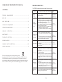
TROUBLE SHOOTINGS
CAUTION: Disconnect the power supply before servicing.
STATUS
CAUSE AND METHOD OF REPAIRING
TOOL
The power
supply is
damaged
If the power supply is damaged,please call
technicians to repair.
the
"+" type
Screwdriver
Sharp Pincers
The lamp
works but the
motor does
not run
a) Remove the vane guard and rotate the vane by
hand,If the vane cannot move smoothly, the core
or bearings of the motor may be damaged. In this
case, replace with a new motor.
b) If the motor stops running and has a bad odor
after a moment of operation, the motor wires may
be burnout. Replace the motor.
c) If the starting wire (yellow) is disengaged from
the condenser, it needs to be rewired.
d) If the condenser is damaged, replace with a new
one.
"+" type
Screwdriver
The lamp works
but the motor
does not run
a) Take off the filter and check the connection
between air inlet and wind chamber is sealed or
not.
b) Check the connection between air exhaust pipe
and wind chamber leaks oil or not. If"YES, please
fill it up with the varnish or the thinner.
"+" type
Screwdriver
Machine vibration
a) If the motors were not firmly screwed, screw tigh
-ten them up.
b) If the vane is damaged or unbalanced, replace
with a new one.
"+" type
Screwdriver
Weakness suction
a) The distance is too far between the Hood and the
Gas Cooker.
b) There are many windows (doors) cause wind con
-vection is too strong.
c) Because of the Hood is set upon the window, the
best solution is that put one three-ply board on
the back of the Hood for covering the hollow of
window.
"+" type
Screwdriver
Installation of
the model is tilt
a) Adjust the height of the model where is hang on
the ceiling.
b) If the model tilt forward, lock into the wall with
wood screw again (the screw peep out around 0.5
~1 cm from the wall), or check the screws for fix
-ing the model are loose or not.
"+" type
Screwdriver
Bulb does not
light
Just screw off the lamp shade and replace with a new
bulb,then put the lamp shade back.
"+" type
Screwdriver
13
CONTENTS
TE CHNICAL CH ARACTERISTI CS .. ........... .................... ........... ........... ........... 1
BO DY SIZE .... ............ ..... ....... ..... ....... ..... ....... ..... ............ ............ ............ ..... ..... 1
MAIN PARTS NAM E. ........................... .. ........................... .. ............................. ...2-3
INSTA L L AT I O N REQUIRE M E N T. . . . . . . . . . . . . . ............... . . . . . . . . . . . . . ................ . . . . . . . . . . . . . 4
INS TALL ATIO N PRO CEDU RES. ....... .... .... ... .... .... .... ... .... .... ... .... .... .... ... .... .... ... ..4- 6
OPERATIO N IN STR UCT ION ................ ... ... ... ... ... ... ... ................ ... ... ... ... ... ... ... ... 7
MAINT E N ANCE. . . ...... . . ...... . . ..... . . ...... . . ..... . . . ..... . . ...... . . ..... . . ...... . . ...... . . ..... . . ...... . . ..8
TO REPLACE LIGH T B ULB ... ... ............. ... ... ... ... ............. ... ... ... ... ... .......... ... ... ... ..8
PARTS REPLACEMENT.....................................................................................................9-10
IMPORTANT SAFETY INSTRUCTIONS..............................................................11-12
TRO UBL E SHO OTI NGS.... ... ... .......... ... ... ....... ... ... .......... ... ... ....... ... ... .......... ... ... ..13
READ AND SAVE THESE INSTRUCTIONS MANUAL
Ple ase no te tha t t his p r oduc t is mar ked wi th thi s symb ol:
Acc ordi n g to Wast e of Ele ctri cal an d Elec tron ic Equ ipme nt (WE EE) di rect i ve,
WEE E shou ld be se p ara t ely co llec ted an d trea ted. I f at any t ime in f utur e you
nee d to dis pose o f t his pr oduc t, Ple ase do N OT di spos e of thi s prod uct wi th hou se
hol d wast e . Ple a se sen d this p rodu ct to WEEE c olle ctin g poin ts whe re ava ilab le.

12
1
Dear consumer,
Thanks for your purchase of our cooker hood and we hope we can fully satisfy all of your needs.
Please read entire instructions carefully before proceeding to obtain the best results of using
the cooker hood.
TECHNICAL CHARACTERISTICS
BODY SIZE
MODEL NO.: RCH-IA90SV-GX, RCH-IA90SM-GX
TOTAL POWER: W
6 SPEED MOTOR: 200W
LED Lights:12V d.c / 2×2W
VOLTAGE: 220V~ 240V
FREQUENCY: 50HZ
FILTER:
CONTROL: Multi-functional sensor switch
204
Glass Panel
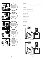
Dress the protective
glove before you start to
clean the hood. Remove the
components gently during
carrying out the
clearance.
Never wash the
control switch with water
or other kind of liquid to avoid
the liquid might cause
electrical problem to
the hood.
To clean the motor
fan should be undertaken
by a qualified person, pay top
attention to avoid any distortion
of the fan during carrying
out the clearance.
Never pull the plug
out of the power supply by
wet hand to avoid the
possibility of electric
shock.
Disconnect the
cooker hood from the
power supply if this appliance
will not be used for
a long time.
Glove
RCH-IA90SV-GX
RCH-IA90SM-GX
8 6 5 - 1 1 8 0
3
2
0
3
6
0
900
4 6 5
3
9
0
3 6 0
4 3 6
900
8 6 5 - 1 1 8 0
4 6 5
3
2
0
3
6
0
3
9
0
3 6 0
4 3 6

RCH-IA90SV-GX
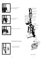
MAIN PARTS NAME
Electrical box
PCB
Hook
Motor
Blower
Oil cup
LED lamp
Inner telescopic duct
Outer telescopic duct
Plastic pipe
Shutter
Blower box
Blower assembly
Bottom cover
Switch PCB
Filter
Screw
Synchronous motor
Glass panel
2
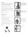
IMPORTANT SAFETY INSTRUCTIONS:
Do not leave naked
flames under this hood
In case of any
damage to power cable,
replace the broken cable with
a new one by qualified person.
To replace the bulb
should be undertaken by a
qualified electrician or a
competent person. Always
use the bulb no more
than 2W.
Do clean the hood
correctly in accordance
with instruction stated or it
might cause the possibility
of fire accident
Do not connect the air
outlet to chimney flues or
combustion gas ducts.
Manual
11
2

Plastic pipe
Inner telescopic duct
Telescopic duct bracket
Outer telescopic duct
Shutter
Blower box
Blower assembly
Bottom cover
Filter
Glass panel
Glass
Switch PCB
Ve ionize
LED lamp
Oil cup
Screw
Blower
Motor
Hook
Electrical box
PCB
The temperature
humidity sensor
RCH-IA90SM-GX
3
Filter
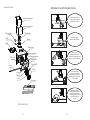
10
Screw
Loose the screws on lamp panel, then
take down the lamp panel.
Loose the screws on filter, then
take down the filter.
Blower
Turn off the blower in clockwise direction.
To replace negative-ion generator
Turn the negative-ion generator in anti
clockwise direction, then take down it.

4
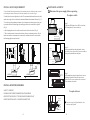
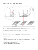
INSTALLATION REQUIREMENT
1. Do not install the cooker hood where there are many doors or windows in order to avoid
to effecting the exhaust efficiency of the hood caused by air convection. (Fig. 1)
2. Install the cooker hood right above the hob. The recommended distance between the hob
and the lower edge of the cooker hood is minimum 300mm and maximum 350mm. (Fig. 2)
3. In order to get the optimum performance, do not elongate the exhaust pipe too long, and
try to make the bend of exhaust pipe less and biggest, ensure the connection is airproof.
(Fig. 3)
4. After hanging the unit on the wall, ensure the hood is level and vertical. (Fig. 4)
5. The air outlet must not be connected to chimney flues or combustion gas ducts. The air
outlet must under no circumstances be connected to ventilation ducts for room in which
fuel-burning appliances are installed.
INSTALLATION PROCEDURES
SAFETY WARNING
HOOD MAY HAVE VERY SHARP EDGES;PLEASE WEAR
PROTECTIVE GLOVES IF IT IS NECESSARY TO REMOVE ANY
PARTS FOR INSTALLING, CLEANING OR SERVICING.
PARTS REPLACEMENT
9
300~350mm
LEVEL
Fig.1 Fig.2 Fig.3
Fig.4
LEAN
Disconnect the power supply before operating.
Step 1:
Take down LED lamps, loose 4PCS screws from
LED lamp holes by cross screwdriver.
Step 2:
Push up and take down the glass panel, remove
the oil cup. Loose 2pcs screw by cross screwdriver,
then push up and take down the glass.
Step 3:
After taking down the glass panel, loose 4 screws
behind glass panel. Remove the switch cover
board, loose 2 screws on the switch cover board.
Then take down the switch.
Screws
2PCS for left side;
2PCS for right side
Glass panel
Glass
Screw
Screw
To replace switch
To replace blower
SS panel
Screw
Loose the screws on SS panel bracket, then
take down the SS panel.

8
5
Step 3:
Matching the bracket to the holes of the inner
duct cover and fix it well with M4 screws.
Matching the bracket to the holes of the Outer
duct cover and fix it well with M4 screws.
Bracket
Inner duct
cover
M4 Screw
Step 4:
Insert the inner duct cover into the
outer duct cover.
Inner duct cover
Outer duct cover
3. Clean the filter once a week or according to use status. Press the buckle of the filter slightly,
take off the filter and put it into warm soapy water using mild detergent, wipe the filter with
soft brush. Replace the filter after it is dry.
4. Clean the motor fan and other inside parts once half year or according to use by QUALIFIED
PERSON.
5. DO NOT cleaning motor with water or other liquid.
MAINTENANCE
CAUTION: NEVER PUT YOUR HAND INTO THE AREA HOUSING WHILE THE FAN IS
OPERATING. FOR THE OPTIMAL LEVEL OF OPERATION, CLEAN THE COOKER
HOOD SURFACE, FAN, AND ALUMINIUM FILTER REGULARLY.
1. Use only mild soap or detergent solutions to clean the cooker hood surface. Dry surfaces
using soft cloth.
2. Using a stainless steel cleaner to bring the glow back into a stainless steel finish.
TO REPLACE LIGHT BULB
To replace led lamp
Caution: LED lamp can not replace a new bulb, just can replace a new LED Lamp.
Make sure all the control switches are off, and he cooker
hood is unplugged! Please follow below instructions:
1.Take out the filters, and cut off the wire connection of the lamp.
2.Press the spring according to the arrow direction, then you can take off the lamp unit.
3.You can replace a new LED lamp unit no more then rating!
4. Then put the lamp unit to the hood in reverse direction. Connect the wire of the lamp.
5. Fit on the filters.
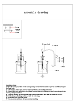
Step 1:
Take down all M4x16 screws from shutter, put
the shutter on gasket for shutter and overlap the
screws holes of the shutter and gasket for shutter.
Use all M4x16 screws to install the shutter and
gasket for shutter to the hood.
Step 2:
Put the exhaust pipe to the shutter as picture
showed. Rotate in direction of arrow. Make sure
the exhaust pipe is fixed and can not be moved.
Blower box
M4x16 Screw
Shutter
Gasket for shutter
Shutter
Plastic pipe

6
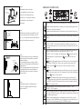
Step 6:
screws to fit the hook on the wall in the screw holes
like 1,2,3,4,5. Then put the hood to the hook make sure
the hood is fixed and can not be moved!
Drill holes in the wall using a 8 mm drill bit. Use five
Step 7:
1. Draw the inner duct cover up to a suitable high,
mark two keyhole of the outer duct cover bracket
on the wall with pen .
2. Put down the inner duct cover gently, drill the
keyholes in 75-85 mm depth on the horizontal level
using 8mm drill.
3. Press the expanding tube provided into the holes.
4. Matching the inner duct cover with the holes,
tighten the inner duct cover with two 5x60 wood
screws provided.
Step 8:
Extend the air outlet of the exhaust pipe out-
of-door. Try to make the bend of the exhaust
pipe more than 120° .
OPERATION INSTRUCTION
7
Wood Screw
5x60
Expanding Tube
Hook
1
4
2
4
3
5
3
6
0
4
6
0
1
2
3
4
5
Step 5:
Matching the holes of outer duct
cover and blower box, fix the outer
duct cover to the blower box using
8pcs of M4 × 10 screws provided with
the fixing tool. As the direction of
illustrated.
Inner duct cover
Outer duct cover
Touch this button, the hood enter into standby mode; Touch again, the hood is
OFF.
Touch this button when the hood is working, it will prolong working for 3mins.
Touch it twice, the hood will turn off.
Touch this button when the hood is in time delay state, the hood will turn off at
once.
Touch this button one time, the lamps will turn on; Touch it again, the lamps will
turn off.
Touch this button when the hood is in standby mode, the fan is changed from
“SOUP” to “STIR” , the air suction is different according to your operation.
Keep touching this button for 2 seconds, the motor is off, the hood is out of time
delay state.
Touch this button when the hood is in standby mode or the hood is working, the
indicator of marked function from four functions(“BOOST”, “AIR”,
“PURIFY”, “ECO”) is flashing. Touch the button of “ ”, the hood enters into
the marked function; Touch the button of “ ”again, the hood is out of the
function.
function: When the hood enters into this function, it will start working in
lowest speed (12CBM/H) for 10mins every two hours once the hood is off.
Touch the button of “ ”or there is a power failure, the hood is out of the
function.
function: When the hood enters into this function, negative ion generator
in hood will produce negative ions. This function will keep on after touching the
button of “ ”or there is a power failure.
function: When the hood enters into this function, according to the
current operating status, the hood will turn into BOOST function automatically
once BOOST is needed. This function will keep on after touching the button of
“ ”or there is a power failure.
Touch this button to set after choosing the function (“BOOST”, “AIR”,
“PURIFY”, “ECO” required.
Touch this button when the hood is working, the hood will go to the highest
speed, with 18CBM/H air suction. Touch again or one minute later, the hood will
come back to primary speed.
Touch this button when the hood is in standby mode, the hood will go to the
highest speed, with 18CBM/H air suction. Touch again or one minute later, the
hood will come back to high speed, with 17CBM/H air suction.
5x60
Wood Screw
Expanding Tube
5x60
Wood Screw
Expanding Tube
-
 1
1
-
 2
2
-
 3
3
-
 4
4
-
 5
5
-
 6
6
-
 7
7
-
 8
8


Rubine RCH-IA90SV-GX User manual
- Category
- Cooker hoods
- Type
- User manual
- This manual is also suitable for
Ask a question and I''ll find the answer in the document
Finding information in a document is now easier with AI
Related papers
-
Rubine RCH-22WM-RS90 User manual
-
-
-
-
-
-
-
-
-
Other documents
-
CWI Lighting 9836W12-3-125 Operating instructions
-
 YISURO Rustic Wall Light Fixtures, Oil Rubbed Bronze Finish Indoor Vintage Wall Light Wall Sconce Industrial Lamp Fixture Glass Shade Farmhouse Metal Sconces Wall Lights for Bedroom Living Room Cafe(2 Pack) User guide
-
Elba EH-N9638ST SS Designer Hood Owner's manual
-
-
 QIAYA QALP24W60D40-01 Installation guide
-
 Astivita ASTCAN60SSGL Instructions Manual
-
PREMIUM PCH7900DR User manual
-
 ARTIVA A202104SN Operating instructions
-
Midea E88 User manual
-
Munchkin Brica Stretch-to-Fit Sun Shade User manual


