Page is loading ...

Instruction Manual
LIQ-MAN-FCLi-1056, Rev E
July 2017
FCLi with 1056
Transmitter

ESSENTIAL INSTRUCTIONS
READ THIS PAGE BEFORE PROCEEDING!
Your purchase from Rosemount, Inc. has resulted in
one of the finest instruments available for your
particular application. These instruments have been
designed, and tested to meet many national and
international standards. Experience indicates that
its performance is directly related to the quality of
the installation and knowledge of the user in oper-
ating and maintaining the instrument. To ensure
their continued operation to the design specifica-
tions, personnel should read this manual thoroughly
before proceeding with installation, commissioning,
operation, and maintenance of this instrument. If
this equipment is used in a manner not specified by
the manufacturer, the protection provided by it
against hazards may be impaired.
• Failure to follow the proper instructions may
cause any one of the following situations to
occur: Loss of life; personal injury; property dam-
age; damage to this instrument; and warranty
invalidation.
• Ensure that you have received the correct model
and options from your purchase order. Verify that
this manual covers your model and options. If
not, call 1-800-854-8257 or 949-757-8500 to
request correct manual.
• For clarification of instructions, contact your
Rosemount representative.
• Follow all warnings, cautions, and instructions
marked on and supplied with the product.
• Use only qualified personnel to install, operate,
update, program and maintain the product.
• Educate your personnel in the proper installation,
operation, and maintenance of the product.
• Install equipment as specified in the Installation
section of this manual. Follow appropriate local
and national codes. Only connect the product to
electrical and pressure sources specified in this
manual.
• Use only factory documented components for
repair. Tampering or unauthorized substitution of
parts and procedures can affect the performance
and cause unsafe operation of your process.
• All equipment doors must be closed and protec-
tive covers must be in place unless qualified per-
sonnel are performing maintenance.
• If this equipment is used in a manner not speci-
fied by the manufacturer, the protection provided
by it against hazards may be impaired.
W
ARNING
RISK OF ELECTRICAL SHOCK
Equipment protected throughout by double insulation.
• Installation of cable connections and servicing of this product
require access to shock hazard voltage levels.
• Main power and relay contacts wired to separate power
source must be disconnected before servicing.
• Do not operate or energize instrument with case open!
• Signal wiring connected in this box must be rated at least
240 V.
• Non-metallic cable strain reliefs do not provide grounding
between conduit connections! Use grounding type bushings
and jumper wires.
• Unused cable conduit entries must be securely sealed by
non-flammable closures to provide enclosure integrity in
compliance with personal safety and environmental protection
requirements. Unused conduit openings must be sealed with
NEMA 4X or IP65 conduit plugs to maintain the ingress
protection rating (NEMA 4X).
• Electrical installation must be in accordance with the National
Electrical Code (ANSI/NFPA-70) and/or any other applicable
national or local codes.
• Operate only with front and rear panels fastened and in place
over terminal area.
• Safety and performance require that this instrument be
connected and properly grounded through a three-wire
power source.
• Proper relay use and configuration is the responsibility of the
user.
CAUTION
This product generates, uses, and can radiate radio frequency
energy and thus can cause radio communication interference.
Improper installation, or operation, may increase such interfer-
ence. As temporarily permitted by regulation, this unit has not
been tested for compliance within the limits of Class A comput-
ing devices, pursuant to Subpart J of Part 15, of FCC Rules,
which are designed to provide reasonable protection against
such interference. Operation of this equipment in a residential
area may cause interference, in which case the user at his own
expense, will be required to take whatever measures may be
required to correct the interference.
W
ARNING
This product is not intended for use in the light industrial,
residential or commercial environments per the instru-
ment’s certification to EN50081-2.

Configure
S1 Measurement
Free Chlorine
pH Independ. Free Cl
Total Chlorine
Monochloramine
Temp Units
o
C
o
F
QUICK START
GUIDE
FOR FCLi
TRANSMITTER
1. Refer to Section 2.0 for installation instructions and Section 3.0 for wiring instructions.
2. Once connections are secured and verified, apply power to the transmitter.
3. When the transmitter is powered up for the first time, Quick Start screens appear. Using Quick Start is
easy. a. A backlit field shows the position of the cursor.
b. To move the cursor left or right, use the keys to the left or right of the ENTER key. To scroll up or down or to increase
or decrease the value of a digit, use the keys above and below the ENTER key. Use the left and right keys to move
the decimal point.
c. Press ENTER to store a setting. Press EXIT to leave without storing changes. Pressing EXIT also returns the
display to the initial Quick Start screen.
d. A vertical black bar with a downward pointing arrow on the right side of the screen means there are more items to
display. Continue scrolling down to display all the items. When you reach the bottom of the list, the arrow will point up.
Language
English
Francais
Espanol
Deutsch
4. Choose the desired language. Scroll down to display more choices.
5. Choose pH-independent free chlorine for sensor 1 (S1).
ppm
mg/L
Units
6. Choose the desired units for chlorine.
S2 Measurement
pH
7. Choose pH for sensor 2 (S2). This screen appears only if you have an
FCLi-02.
ORP
Redox
Ammonia
8. Choose the desired temperature units.
9. The main display appears. The outputs and alarms (if an alarm board is present) are assigned to default values.
10. To change outputs, alarms, and other settings go to the main menu and choose Program. Follow the prompts. A
menu tree is on the following two pages. To calibrate the sensor(s) refer to section 6.0.

MENU
TREE
Calibrate
Sensor 1 (Free chlorine)
Chlorine
Zero
In process
Temperature
Sensor 2 (pH)
pH
Buffer Cal
Auto
Select buffer (NIST, DIN19267, Ingold, Merck, or Fisher)
Select stability criteria
Manual
Standardize
Enter slope or offset
Temperature
Output 1
Output 2
Hold
Sensor 1
Sensor 2
Display
Main format configuration
Language selection
Warning (enable or disable)
Screen contrast
See next page for rest of menu tree

MENU TREE (continued)
Program
Outputs
Range (assign values to 4 and 20 mA)
Configure
Output 1 or 2
Assign sensor and measurement
Range
Scale
Dampening
Fault mode (fixed or live)
Fault value (output current)
Simulate
Alarms
Configure/Setpoint
Alarm 1, 2, 3, or 4
Setpoint
Assign sensor and measurement
High or low logic
Deadband
Interval time
On time
Recovery time
Simulate
Synchronize timers
Measurement
Free chlorine (sensor 1)
Measurement selection
Units
Filter
Resolution
pH (sensor 2)
Measurement selection
Preamplifier location
Solution temperature correction
Resolution
Filter
Reference impedance (high or low)
Temperature
Units
Temperature compensation (auto or manual)
Set manual temperature (if selected)
Security
Calibrate/Hold only
All
Diagnostic Setup
Reference Offset
Diagnostics (on or off)
Glass impedance temperature correction
Glass fault high
Reference fault high
Reset Transmitter

About This Document
This manual contains instructions for installation and operation of the Model FCLi-1056
The following list provides notes concerning all revisions of this document.
Rev. Level
Date
Notes
A
1/08
This is the initial release of the product manual. The manual has been
reformatted to reflect the Emerson documentation style and updated to
reflect any changes in the product offering.
B
08/09
Update DNV / ISO Approval
C
5/11
Update specifications, part numbers, add information for new pH sensor
3900, added warning and wiring diagrams in sec 3, add electrical shock
warning sec 8.0, modified instructions for cleaning the pH sensor and
replacement parts tables sec 8
D
03/12
Update addresses - mail and web
E
07/17
Changed instances of analyzer to transmitter. Replaced Rosemount
Analytical with Rosemount. Replaced Emerson Process Management
with Emerson. Updated addresses and logos and reformatted back
page.

MODEL FCLI-1056 TABLE OF CONTENTS
FCLi-1056
TABLE OF CONTENTS
Section Title Page
1.0 DESCRIPTION AND SPECIFICATIONS ................................................................ 1
1.1 Applications and Features ..................................................................................... 1
1.2
Specifications
........................................................................................................... 2
1.3 Ordering Information ................................................................................................ 3
2.0
INSTALLATION
....................................................................................................... 5
2.1 Unpacking and Inspection........................................................................................ 5
2.2
Inst
allation ................................................................................................................ 5
3.0 WIRING.................................................................................................................... 9
3.1 Preparing Conduit Openings.................................................................................... 9
3.2 Power, Alarm, Output, and Sensor Connections ..................................................... 10
4.0 DISPLAY AND
OPERATION
................................................................................... 13
4.1 Display ..................................................................................................................... 13
4.2 Keypad ..................................................................................................................... 14
4.3 Programming the Transmitter - Tutorial........................................................................ 15
4.4 Security .................................................................................................................... 16
4.5 Using Hold ............................................................................................................... 17
4.6 Configuring the Main Display ................................................................................... 18
5.0 PROGRAMMING THE TRANSMITTER ........................................................................ 19
5.1 General .................................................................................................................... 19
5.2 Default Settings........................................................................................................ 19
5.3 Configuring, Ranging and Simulating
Output
s ......................................................... 22
5.4 Configuring Alarms and Assigning Setpoints ........................................................... 25
5.5 Configuring the Measurement.................................................................................. 30
5.6 Configuring Temperature Related Settings .............................................................. 32
5.7 Configuring Security Settings................................................................................... 33
5.8 Setting up Diagnostics ............................................................................................. 34
5.9 Resetting the Transmitter ............................................................................................. 36
6.0 CALIBRATION ........................................................................................................ 37
6.1 Introduction .............................................................................................................. 37
6.2 Calibrating Temperature........................................................................................... 37
6.3 Calibration - Free Chlorine ...................................................................................... 39
6.4 Calibration - pH ....................................................................................................... 42
6.5 Calibration - Analog
Output
s .................................................................................... 49
i

MODEL FCLi-1056
TABLE OF CONTENTS
TABLE OF CONTENTS CONT’D
Section Title Page
7.0 DIGITAL COMMUNICATIONS ............................................................................... 51
8.0 MAINTENANCE ...................................................................................................... 53
8.1 Transmitter ................................................................................................................... 53
8.2 Chlorine Sensor ....................................................................................................... 54
8.3 pH Sensor ................................................................................................................ 56
8.4 Constant Head Flow Controller ................................................................................ 56
9.0 TROUBLESHOOTING ........................................................................................... 59
9.1 Overview .................................................................................................................. 59
9.2 Using the Diagnostic Feature................................................................................... 59
9.3 Troubleshooting When a Fault Message is Showing .............................................. 60
9.4 Troubleshooting When a Warning Message is Showing.......................................... 63
9.5 Troubleshooting When No Error Message is showing - Chlorine ............................ 64
9.6 Troubleshooting When No Error Message is showing - pH ..................................... 67
9.7 Troubleshooting When No Error Message is showing - General ............................. 70
9.8 Simulating Inputs - Chlorine ..................................................................................... 70
9.9 Simulating Inputs - pH.............................................................................................. 70
9.10 Simulating Inputs Temperature ................................................................................ 71
LIST OF
T
ABLES
Number Title Page
1.3
Ordering Information ...............................................................................................
3
1.3
Component Parts .....................................................................................................
3
1.3
Accessories ..............................................................................................................
3
1.3
Spare Parts...............................................................................................................
3
3.2
Sensor Wiring ...........................................................................................................
10
4.6
Configuring the Main Display ...................................................................................
18
5.1
Default Settings ........................................................................................................
20
5.1
Default Settings cont ................................................................................................
21
5.7
Configuring Security Settings ...................................................................................
33
5.8.2
Procedure - Setting Up Diagnostics .........................................................................
35
6.4
Calibration - pH ........................................................................................................
42
8.1
Transmitter ...................................................................................................................
53
8.2.3
Spare Parts ..............................................................................................................
55
8-2
Replacement Parts for Constant Head Flow Controller Assembly (Model FCLi-01)
................................................................................................................................
57
8-3
Replacement Parts for Constant Head Flow Controller Assembly (Model FCLi-02)
................................................................................................................................
58
9.3
Troubleshooting When a Fault Message is Showing ...............................................
60
9.4
Troubleshooting When a Warning Message is Showing ..........................................
63
9.5
Troubleshooting When No Error Message is Showing - Chlorine ............................
64
9.6
Troubleshooting When No Error Message is Showing - pH .....................................
67
ii

MODEL FCLi-1056
TABLE OF CONTENTS
LIST OF TABLES CONT’D
9.6.1 Calibration Error During Two-Point Calibration ........................................................ 67
9.7 Troubleshooting When No Error Message is Showing - General............................. 70
9.9.2 Simulating pH Input .................................................................................................. 70
9.10 Simulating Inputs Temperature................................................................................. 72
LIST OF
FIGURES
Number Title Page
2-1 Chlorine Sensor Parts .............................................................................................. 7
2-2 Model FCLi-01 .......................................................................................................... 8
2-3 Model FCLi-02 .......................................................................................................... 8
3-1 Analog Output Connections ..................................................................................... 9
3-2 Alarm Relay Connections ......................................................................................... 10
3-3 Wiring Diagram for Free Chlorine Sensor ................................................................ 11
3-4 Wiring Diagram for 399VP-09 pH Sensor ............................................................... 11
3-5 Wiring Diagram for 3900VP-10 pH sensor (gray cable) ........................................... 11
3-6 Wiring Diagram for 3900VP-10 pH sensor (blue cable) ........................................... 11
4-1 Main Display ............................................................................................................. 13
4-2 Programming Screen Showing Item List .................................................................. 13
4-3 Arrow Bar ................................................................................................................. 13
4-4 Transmitter Keypad ...................................................................................................... 14
4.5 Navigation Keys ....................................................................................................... 14
5-1 High Alarm Logic ..................................................................................................... 26
5-2 Low Alarm Logic ...................................................................................................... 26
5-3 Operation of the Interval
T
imer ................................................................................. 26
6-1 Sensor Current as a Function of Free Chlorine Concentration ................................ 39
6-2 Calibration Slope and Offset .................................................................................... 42
8-1 Chlorine Sensor Parts .............................................................................................. 55
8-2 Replacement Parts for the Flow Controller Assembly used in Model FCLi-01 ......... 57
8-3 Replacement Parts for the Flow Controller Assembly used in Model FCLi-02 ......... 58
9-1 Pin Out Diagram for Model 498CL-01-VP Sensor ................................................... 61
9-2 Pin Out Diagram for Model 399VP-09 Sensor ......................................................... 61
9-3 Simulating pH Inputs ................................................................................................ 70
9-4 Three-Wire RTD Configuration................................................................................. 71
9-5 Simulating TRD Inputs.............................................................................................. 71
iii

THIS PAGE LEFT BLANK INTENTIONALLY

Model FCLi-1056 SECTION 1.0
DESCRIPTION AND
SPECIFICATIONS
SECTION 1.0. DESCRIPTION AND
SPECIFIC
A
TIONS
• COMPLETE SYSTEM INCLUDES sensor, connecting cable, transmitter, and flow controller
• SENSOR RESPONSE IS PRACTICALLY INDEPENDENT of pH between pH 6 and 10
• NO REAGENTS
• NO AUXILIARY pH ELECTRODE
• VARIOPOL QUICK-DISCONNECT FITTINGS makes sensor replacement easy
1.1 APPLICATIONS AND FEATURES
The FCLi free chlorine system is intended for the
determination of free chlorine (hypochlorous acid plus
hypochlorite ion) in fresh water. Unlike other free chlo-
rine transmitters, the FCLi does not use expensive
sam- ple conditioning systems or messy reagents to
control pH. Nor, does it require an auxiliary pH sensor
for pH correction. Instead, the pH adjustment takes
place inside the sensor, producing a signal that
changes less than 4% per unit change in pH between
pH 6 and
10. Below pH 6.5 the change is less than 1%. The lin-
ear range of the sensor is 0 to 20 ppm (mg/L).
The FCLi is not intended for the determination of total
or combined chlorine (like monochloramine). Nor, can
the FCLi be used for the determination of chlorine in
seawater.
The FCLi uses a three electrode, membrane-covered
amperometric sensor. The sensor consists of a
hydrophilic membrane stretched over a gold mesh
cathode. A silver/silver chloride reference electrode
and an external copper auxiliary electrode complete
the circuit. The fill solution is saturated succinic acid
slurry. During operation, an electrochemical reaction,
driven by the polarizing voltage, consumes free chlo-
rine at the cathode surface. The auxiliary electrode
provides the electrons for the cathode reaction, and
a current proportional to the reaction rate flows
between the electrodes. Because the concentration of
chlorine at the cathode is zero, free chlorine in the
sample continuously diffuses through the membrane
and is destroyed at the cathode. Thus, the cathode
current is proportional to the diffusion rate, which is
proportional to the concentration of free chlorine in the
sample.
The FCLi sensor requires neither sample pretreatment
nor pH correction. All amperometric free chlorine sen-
sors generate a raw current that depends primarily on
the concentration of hypochlorous acid. Because the
fraction of free chlorine present as hypochlorous acid
is a function of pH, readings will be in error if the sam-
ple pH changes from the value it had during calibra-
tion. To correct for pH changes, some manufacturers
treat the sample with acid to convert hypochlorite to
hypochlorous acid. Others continuously measure the
pH and use the pH value to correct the chlorine sensor
reading. The Model FCLi is different. The sensor uses
a highly buffered acidic fill solution for internal pH
adjustment. The fill solution converts all the free chlo-
rine entering the sensor as well as much of the free
chlorine at the outside surface of the membrane into
hypochlorous acid. Thus, the sensor response is prac-
tically independent of pH.
For customers who wish to measure pH, an option
that includes a pH sensor and flow cell is available.
Maintenance is fast and easy. Replacing a membrane
requires no special tools or fixtures. A screw cap holds
the pre-tensioned membrane in place. Replacing the
membrane and fill slurry takes only a few minutes.
The FCLi includes the easy-to-use Model 1056 ana-
lyzer. The transmitter features two fully programmable
4-
20 mA analog outputs. Programming and calibration is
simple and intuitive. The backlit, four-line display
allows the user to read chlorine (and pH) at a single
glance.
Valves, rotameters, and pressure regulators to control
sample flow are things of the past with the Model
FCLi. A constant head overflow sampler ensures the
correct flow to the sensor no matter how much the
sample flow or pressure changes. To eliminate wiring
hassles, quick disconnect Variopol cable is standard.
Stable free chlorine standards do not exist. The chlo-
rine sensor must be calibrated using the results of a
laboratory test run on a grab sample.
1

MODEL FCLi-1056
SECTION 1.0
DESCRIPTION AND SPECIFICATIONS
1.2 SPECIFICATIONS — GENERAL
Sample requirements:
Pressure: 3 to 65 psig (122 to 549 kPa abs)
A check valve in the inlet opens at 3 psig (122
kPa abs). If the check valve is removed, mini-
mum pressure is 1 psig (108 kPa abs).
Temperature: 32 to 122°F (0 to 50°)
Minimum Flow: 2 gal/hr (7.6 L/hr)
Maximum flow: 80 gal/hr (303 L/hr); high flow
causes the overflow tube to back up.
Sample Conductivity: >10 µS/cm
Process connection: 1/4-in OD tubing compression
fitting (can be removed and replaced with barbed
fitting for soft tubing).
Drain connection: 3/4-in barbed fitting. Sample must
drain to open atmosphere.
Wetted parts:
Overflow sampler: acrylic, polycarbonate,
polyester, Kynar
1
, nylon, silicone
Chlorine sensor: PVC, Viton
2
, silicone, polyether-
sulfone, polyester, gold, and copper (or 316
stainless steel)
pH sensor (3900VP) : Stainless steel, glass,
Teflon
®2
, polyphenylene sulfide, EPDM, and
silicone
Response time to step change in chlorine concen-
tration: <120 sec to 90% of final reading for inlet
sample flow of 2 gph (7.6 L/hr).
Weight/shipping weight:
Model FCLi-01: 10 lb/13 lb (4.5 kg/6.0 kg)
Model FCLi-02: 11 lb/14 lb (5.0 kg/6.5 kg)
[rounded to the nearest 1 lb. (0.5 kg)]
SPECIFICATIONS — SENSOR
Free chlorine range: 0 to 20 ppm as Cl
2
. For higher
ranges, consult the factory.
Accuracy: Accuracy depends on the accuracy of the
chemical test used to calibrate the sensor
Linearity (0-20 ppm): 1% per IEC 60746
Linearity (0-2 ppm): ±0.05 ppm following calibration
at 2 ppm
Sensitivity to pH: Between pH 6.5 and 10, sensor
signal changes <4% per unit change in pH. Below
pH 6.5 the change is <1% per unit change in pH.
Interferences: Monochloramine, dichloramine,
permanganate, and peroxides
Electrolyte life: 3 months (approx.)
SPECIFICATIONS — TRANSMITTER
Case: Polycarbonate, NEMA 4X/CSA4 (IP65)
Display: Monochromatic back-lit LCD. Main character
height 0.6 in (15 mm). Display is user-programable.
Languages: English, German, Italian, Spanish,
French, Portuguese
Ambient temperature and humidity: 32 to 131°F
(0 to 55°C); RH 5 to 95% (con-condensing)
Storage temperature: -4 to 140°F (-20°C and 60°C)
Power: 85 to 265 Vac, 47.5-65.0 Hz, 15 W.
Equipment protected by double insulation.
RFI/EMI: EN-61326
LVD: EN-61010-1
Outputs: Two 4-20 mA or 0-20 mA isolated outputs.
Continuously adjustable. Linear or logarithmic.
Maximum load 550 ohms. Output dampening with
time constant of 5 sec is user-selectable.
Alarms: Four alarm relays for process meas-
urement(s) or temperature. Any relay can be
configured as a fault alarm instead of a
process alarm. Each relay can be configured
independently and each can be programmed
with interval timer settings.
Relays: Form C, SPDT, epoxy sealed
Relay Contact ratings:
5 A at 28 VDC or 300 VAC (resistive)
1/8 HP at 120/240 VAC.
Terminal Connections Rating: Power connector
(3-leads): 18-12 AWG wire size. Current output
connectors (2-leads): 24-16 AWG wire size. Alarm
relay terminal blocks: 18-16 AWG wire size
1
Kynar is a registered trademark of Elf Atochem North America.
2
Viton and Teflon are registered trademarks of DuPont
Performance Eastomers.
2

MODEL FCLi-1056
SECTION 1.0
DESCRIPTION AND SPECIFICATIONS
1.3 ORDERING INFORMATION
FCLi Free Chlorine Measuring System. The FCLi is a complete system for the determination of free chlorine in
aqueous samples. It consists of the sensor(s), transmitter, and constant head flow controller. All components are
mounted on a backplate. Model option -02 includes a pH sensor for customers who wish to measure pH in addi-
tion to free chlorine. Three replacement membranes and enough electrolyte chemicals to fill the sensor three
times are shipped with each sensor.
FCLi FREE CHLORINE MEASURING SYSTEM
CODE
pH CORRECTION (required selection)
01
Without pH sensor
02
With pH sensor
CODE
pH CORRECTION (required selection)
220
1056-03-24-38-AN, 115/230 Vac 50/60 Hz, alarm relays, analog outputs, chlorine only (option -01 only)
221
1056-03-24-32-AN, 115/230 Vac 50/60 Hz, alarm relays, analog outputs, chlorine and pH (option -02 only)
FCL
i
-02 -221 EXAMPLE
COMPONENT PARTS
TRANSMITTER
MODEL
DESCRIPTION
1056-03-24-38-AN
1056-03-24-38-AN, 115/230 Vac 50/60 Hz, alarm relays, analog outputs, chlorine only
1056-03-24-32-AN
1056-03-24-32-AN, 115/230 Vac 50/60 Hz, alarm relays, analog outputs, chlorine and pH
SENSOR MODEL
DESCRIPTION
498CL-01-VP
pH-independent free chlorine sensor with Variopol connector
3900VP-02-10
pH sensor with Variopol connector
SENSOR CABLE
DESCRIPTION
24150-00
Interconnecting cable, Variopol for 498ACL sensor, 4 ft
23645-08
Interconnecting cable, Variopol for 3900VP sensor (gray), 4 ft
24281-05
Interconnecting cable, Variopol for 3900VP sensor (blue), 4 ft
ACCESSORIES
PART #
DESCRIPTION
9240048-00
Tag, stainless steel (specify marking)
SPARE PARTS
PART #
DESCRIPTION
33970-00
Fill plug
33968-00
Membrane retainer
9550094
O-ring, 2-014, Viton
®
23501-10
pH-independent free chlorine membrane assembly, includes one membrane assembly and O-ring
23502-10
pH-independent free chlorine membrane assembly, includes three membrane assemblies and three
O-rings
24146-00
pH-independent free chlorine sensor electrolyte kit, includes three bottles of saturated succinic acid and
three bottles of succinic acid crystals
3

MODEL FCLi-1056
SECTION 1.0
DESCRIPTION AND SPECIFICATIONS
4

MODEL FCLi-1056
SECTION 2.0
INST
ALLA
TION
SECTION
2.0.
INSTALL
A
TION
2.1 UNPACKING AND INSPECTION
Inspect the shipping container. If it is damaged, contact the shipper immediately for instructions. Save the box.
If there is no apparent damage, unpack the container. Be sure all items shown on the packing list are present.
If items are missing, notify Rosemount immediately.
2.1.1 MODEL FCLi-01-220 (free chlorine without pH sensor)
Model consists of the following items mounted on a back plate.
1. Model 1056-03-24-38-AN transmitter with sensor cable
attached.
2. Constant head overflow sampler with flow cell for chlorine sensor.
The free chlorine sensor (Model 498CL-01-VP) is in a separate package. The sensor is shipped with three membrane
assemblies and enough electrolyte chemicals to fill the sensor three times.
2.1.1 MODEL FCLi-02-221 (free chlorine with pH sensor)
Model consists of the following items mounted on a back plate.
1. Model 1056-03-24-32-AN transmitter with sensor cables
attached.
2. Constant head overflow sampler with flow cells for chlorine and pH sensors.
3. Stand to hold buffer solution during calibration.
The free chlorine sensor (Model 498CL-01-VP) and the Model 3900VP-02-10 pH sensor, which replaces the older
Model 399VP-09 sensor, are in separate packages. The free chlorine sensor is shipped with three membrane
assemblies and enough electrolyte chemicals to fill the sensor three times.
5

MODEL FCLi-1056
SECTION 2.0
INST
ALLA
TION
2.2 INSTALLATION
2.2.1 General Information
1. Although the system is suitable for outdoor use, do not install it in direct sunlight or in areas of extreme
temperature.
CAUTION
The FCLi free-chlorine system is
NOT
suitable for use in hazardous areas.
2. To keep the transmitter enclosure watertight, install plugs (provided) in the unused cable openings.
3. Install the system in an area where vibrations and electromagnetic and radio frequency interference are
minimized or absent.
4. Be sure there is easy access to the transmitter and sensors.
2.2.2 Sample Requirements
Be sure the sample meets the following requirements:
1. Temperature: 32 to 122ºF (0 to 50ºC)
2. Pressure: 3 to 65 psig (122 to 549 kPa abs)
3. Minimum flow: 2 gal/hr (7.6 L/hr)
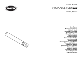
2.2.3 Mounting and Making Inlet and Drain Connections
The FCLi is intended for wall mounting only. Refer to Figure 2-2 or 2-3 for details.
A 1/4-inch OD tubing compression fitting is provided for the sample inlet. If desired, the compression fitting can
be removed and replaced with a barbed fitting. Do not remove the check valve. The threads are 1/4-inch FNPT.
The sample drains through a 3/4-inch barbed fitting. Attach a piece of soft tubing to the fitting and allow the waste
to drain to open atmosphere. Do not restrict the drain line.
Adjust the sample flow until the water level is even with the central overflow tube and excess water is flowing down
the tube. Confirm that sample is flowing through the flow cells.
2.2.4 Electrical Connections
Refer to Section 3.1 for details.
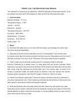
2.2.5 Installing the Sensor(s)
1. The chlorine sensor leaves the factory with a shipping membrane in place. The shipping membrane
must be removed and replaced with the chlorine membrane before putting the sensor in service. The
chlorine membrane is in a plastic bag attached to the sensor. Do not remove the shipping membrane
until you are ready to put the sensor in service.
a. Remove the red protective cap from the end of the sensor.
b. Holding the membrane end pointing up (cable connector end pointing down), unscrew the retainer cap
and remove the shipping membrane. See Figure 2.1. It is not necessary to remove the O-ring. Save the
shipping membrane. It should be reinstalled on the sensor when the sensor is not in use.
c. Still holding the membrane end pointing up, install the chlorine membrane. The chlorine membrane is in
the plastic bag attached to the sensor. Screw the retainer back in place.
6

MODEL FCLi-1056
SECTION 2.0
INST
ALLA
TION
cable
end
fill plug
o-ring
membrane
assembly
auxiliary
electrode
membrane
retainer cap
FIGURE 2-1. Chlorine Sensor Parts
2. If you are using a pH sensor, remove the protective cap on the sensor.
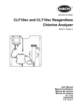
3. Install the sensors in the flow cells as shown in Figures 2.2 and 2.3. For Model FCLi-02-221, the pH sensor
must be installed as shown in Figure 2.3. The chlorine sensor sits in the flow cell and is held in place by the
union nut. The pH sensor screws into a plastic fitting, which the union nut holds in the flow cell. Be sure to
slip the union nut over the sensor before connecting the cable to the sensor.
4. The Model FCLi is provided with sensor cables pre-wired to the transmitter. Connect the chlorine sensor to
the cable labeled Chlorine Sensor. Connect the pH sensor to the cable labeled pH Sensor. The terminal end
of the sensor is keyed to ensure proper mating with the cable receptacle. Once the key has slid into the
mating slot, tighten the connection by turning the knurled ring clockwise.
NOTE
The chlorine sensor is available in two styles. One has a copper auxiliary electrode; the other has a stain-
less steel auxiliary electrode. The auxiliary electrode is the metal band visible at the bottom of the sen-
sor. The copper electrode is gradually being phased out and replaced by a stainless steel electrode.
If the sensor has a copper electrode…Generally, it is best to keep the sensor in a continuously flowing
sample. The sensor can tolerate loss of sample flow for about four days as long as it remains immersed
in water in the flow cell. A check valve in the sample inlet prevents water from draining out of the flow
cell. If the sensor sits too long in a stagnant sample, copper ions from the air oxidation of the electrode
can diffuse into the sensor. Once inside the sensor, the copper undergoes an electrochemical reaction
that greatly increases the background current and can potentially damage the sensor. See step 2 in
Section 6.3.2 for more information.
If the sensor has a
stainless
steel electrode…The stainless steel electrode is not susceptible to air oxi-
dation. Therefore, loss of sample flow does not normally present a problem.
Do not expose the chlorine sensor to air for any longer than an hour. Prolonged exposure to air will cause
the membrane to dry out. Once this happens, the membrane must be replaced.
7

MODEL FCLi-1056
SECTION 2.0
INST
ALLA
TION
INCH
MILLIMETER
CHLORINE SENSOR
CHECK VALVE
INLET
DRAIN
FIGURE 2-2. Model FCLi-01-220
INCH
MILLIMETER
CHLORINE SENSOR
pH SENSOR
CHECK
VALVE
INLET
DRAIN
FIGURE 2-3. Model FCLi-02-221
8

MODEL FCLi-1056
SECTION 3.0
WIRING
SECTION
3.0.
WIRING
3.1 POWER, ALARM, AND OUTPUT WIRING
W
ARNING
RISK OF ELECTRICAL SHOCK
Electrical installation must be in accordance with the National Electrical Code
(ANSI/NFPA-70) and/or any other applicable national or local code.
3.1.1 Power
Wire AC mains power to the power supply board, which is mounted vertically on the left hand side of the analyz-
er enclosure. The power connector is at the top of the board. Unplug the connector from the board and wire the
power cable to it. Lead connections are marked on the connector. (L is live or hot; N is neutral, the ground con-
nection has the standard symbol.)
AC power wiring should be 14 gauge or greater. Run the power wiring through the conduit opening nearest the
power terminal. Provide a switch or breaker to disconnect the transmitter from the main power supply. Install the
switch or breaker near the transmitter and label it as the disconnecting device for the transmitter.
3.1.2 Analog output wiring
Two analog current outputs are located on the main circuit board, which is attached to the inside of the enclosure
door. Figure 3-1 shows the location of the terminals. The connectors can be detached for wiring. TB-1 is output 1.
TB-2 is output 2. Polarity is marked on the circuit board.
For best EMI/RFI protection, use shielded output signal cable enclosed in earth-grounded metal conduit.
Keep output signal wiring separate from power wiring. Do not run signal and power or relay wiring in the same
conduit or close together in a cable tray.
FIGURE 3-1. Analog output connections. The analog outputs are on the main
board near the hinged end of the enclosure door.
9

MODEL FCLi-1056
SECTION 3.0
WIRING
3.1.3 Alarm wiring.
WARNING
Exposure to some chemicals may degrade the sealing
properties used in the following devices: Zettler
Relays (K1-K4) PN AZ8-1CH12DSEA
The alarm relay terminal strip is located just below the
power connector on the power supply board. See
Figure 3-2.
Keep alarm relay wiring separate from signal wiring.
Do not run signal and power or relay wiring in the
same conduit or close together in a cable tray.
FIGURE 3-2. Alarm relay connections.
3.2 SENSOR WIRING
The Model FCLi is provided with sensor cables pre-wired to the transmitter. If it is necessary to replace the
sensor cable, refer to the instructions below.
1. Shut off power to the transmitter.
2. Loosen the four screws holding the front panel in place and let it drop down.
3. Locate the appropriate signal board.
Slot 1 (left)
Slot 2 (center)
Slot 3 (right)
communication
input 1 (chlorine)
input 2 (pH)
4. Loosen the gland fitting and carefully push the sensor cable up through the fitting as you pull the board
forward to gain access to the wires and terminal screws. Disconnect the wires and remove the cable.
5. Insert the new cable through the gland and pull the cable through the cable slot.
6. Wire the sensor to the signal board. Refer to the wiring diagrams in Figures 3-3 and 3-4.
7. Once the cable has been connected to the board, slide the board fully into the enclosure while taking up the
excess cable through the cable gland. Tighten the gland nut to secure the cable and ensure a sealed enclosure.
10
/