Page is loading ...

INSTALLATION/OPERATION &
TECHNICAL MANUAL
FOR JACKSON MODELS:
AND ASSOCIATED OPTION PACKAGES INCLUDING:
SIDE LOADER
D226 EXTERNAL STEAM BOOSTER
Jackson MSC LLC.
P.O. Box 1060
Barbourville, KY. 40906
(606) 523-9795
Fax: (606) 523-9196
www.jacksonmsc.com
AJ-54 RACK CONVEYOR DISHMACHINE SERIES
April 19, 2007
P/N 7610-002-30-91 (Revision E)
AJ-54CE
AJ-54CGP
AJ-54CS
AJ-76CE
AJ-76CGP
AJ-76CS
AJ-90CE
AJ-90CS

ALL NEW JACKSON DISHWASHERS ARE WARRANTED TO THE ORIGINAL PURCHASER TO BE FREE FROM
DEFECTS IN MATERIAL OR WORKMANSHIP, UNDER NORMAL USE AND OPERATION FOR A PERIOD OF (1) ONE
YEAR FROM THE DATE OF PURCHASE, BUT IN NO EVENTTO EXCEED (18) EIGHTEEN MONTHS FROM THE DATE
OF SHIPMENT FROM THE FACTORY.
Jackson MSC agrees under this warranty to repair or replace , at its discretion, any original part which fails under normal use due to faulty
material or workmanship during the warranty period, providing the equipment has been unaltered, and has been properly installed, main-
tained and operated in accordance with the applicable factory instruction manual furnished with the machine and the failure is reported to
the authorized service agency within the warranty period. This includes the use of factory specified genuine replacement parts, purchased
directly from a Jackson authorized parts distributor or service agency. Use of generic replacement parts may create a hazard and void war-
ranty certification.
The labor to repair or replace such failed part will be paid by Jackson MSC, within the continental United States, Hawaii and Canada, during
the warranty period provided a Jackson MSC authorized service agency, or those having prior authorization from the factory, performs the
service. Any repair work by persons other than a Jackson MSC authorized service agency is the sole responsibility of the customer. Labor
coverage is limited to regular hourly rates, overtime premiums and emergency service charges will not be paid by Jackson MSC.
Accessory components not installed by the factory carry a (1) one year parts warranty only. Accessory components such as table limit switch-
es, pressure regulators, pre rinse units, etc. that are shipped with the unit and installed at the site are included. Labor to repair or replace
these components is not covered by Jackson MSC.
This warranty is void if failure is a direct result from shipping, handling, fire, water, accident, misuse, acts of god, attempted repair by unau-
thorized persons, improper installation, if serial number has been removed or altered, or if unit is used for purpose other than it was origi-
nally intended.
TRAVEL LIMITATIONS
Jackson MSC limits warranty travel time to (2) two hours and mileage to (100) one hundred miles. Jackson MSC will not pay for travel time
and mileage that exceeds this, or any fees such as those for air or boat travel without prior authorization.
WARRANTY REGISTRATION CARD
The warranty registration card supplied with the machine must be returned to Jackson MSC within 30 days to validate the warranty.
REPLACEMENT PARTS WARRANTY
Jackson replacement parts are warranted for a period of 90 days from the date of installation or 180 days from the date of shipment from the
factory, which ever occurs first.
PRODUCT CHANGES AND UPDATES
Jackson MSC reserves the right to make changes in design and specification of any equipment as engineering or necessity requires.
THIS IS THE ENTIRE AND ONLY WARRANTY OF JACKSON MSC. JACKSON’S LIABILITY ON ANY CLAIM OF ANY KIND, INCLUDING
NEGLIGENCE, WITH RESPECT TO THE GOODS OR SERVICES COVERED HEREUNDER, SHALL IN NO CASE EXCEED THE PRICE
OF THE GOODS OR SERVICES OR PART THEREOF WHICH GIVES RISE TO THE CLAIM.
THERE ARE NO WARRANTIES, EXPRESSED OR IMPLIED, INCLUDING FOR FITNESS OR MERCHANTABILITY, THAT ARE NOT SET
FORTH HEREIN, OR THAT EXTEND BEYOND THE DURATION HEREOF. UNDER NO CIRCUMSTANCES WILL JACKSON MSC BE
LIABLE FOR ANY LOSS OR DAMAGE, DIRECT OR CONSEQUENTIAL, OR FOR THE DAMAGES IN THE NATURE OF PENALTIES,
ARISING OUT OF THE USE OR INABILITY TO USE ANY OF ITS PRODUCTS.
ITEMS NOT COVERED
This warranty does not cover cleaning or deliming of the unit or any component such as, but not limited to, wash arms, rinse arms or strain-
ers at anytime. Nor does it cover adjustments such as, but not limited to timer cams, thermostats or doors, beyond 30 days from the date
of installation. In addition, the warranty will only cover the replacement of wear items such as curtains, drain balls, door guides or gaskets
during the first 30 days after installation. Also, not covered are conditions caused by the use of incorrect (non-Commercial) grade detergents,
incorrect water temperature or pressure, or hard water conditions.
MANUFACTURERS WARRANTY
ONE YEAR LIMITED PARTS & LABOR WARRANTY
i

ii
STOP!
PARE!
ARRET!
CALL 1-888-800-5672 TO REGISTER THIS PRODUCT!
FAILURE TO DO SO WILL VOID THE WARRANTY!
LLAME AL 1-888-800-5672 PARA REGISTRAR ESTE PRODUCTO!
AL NO HACERLO LA GARANTIA SERA ANULADA!
S.V.P. APPELER 1-888-800-5672 POUR ENREGISTRER CE PRODUIT,
LA GARANTIE SERA ANNULEE POUR TOUT PRODUIT NON- ENREGISTREE

iii
REVISION
REVISION
DATE
MADE
BY
APPLICABLE
ECN
DETAILS
B 02-19-04 CBW N/A
Combined AJ-54, AJ-76 and AJ-90 service and export manuals
into one manual. Added data for 575 Volt & 600 Volt models.
C 03-16-05 MAW
6999, 7193
7217, 7064
7212, 7259
6685, 7096
6964, 7006
Updated drawings for limit switch actuators. Changed AJ-76 drain
plumbing copper lengths. Added rack rail stabilizer kit. Replaced
heater 04540-121-76-93 with 04540-002-29-82. Updated installa-
tion instructions. Added 3 instruction sheets for limit switches.
Added instruction sheet for curtains. Added AJ-54CGP & AJ-
76CGP models.
D 02-01-06 MAW 7600
Added gas exhaust fan hookup schematic, updated electric
exhaust fan schematic and updated dimension drawings.
E 03-22-06 MAW
7571, 7330
7634, 7558
7367, 7428
7554, 7462
7463
Added thermostat replacement kits. Added vent cowl assembly for
hooded side loader. Replaced rinse drain weldment. Added scrap
basket strainer kit. Added new door weldments. Added pawl bar
relacement kits. Added heater replacement kits. Added wash,
rinse & psi decals. Added rinse fill motor assemblies.
PG. 115 04-19-07 MAW 7898 Added 09905-003-32-20 fan load decal.

iv
NOMENCLATURE FOR THE MODELS COVERED IN THIS MANUAL
AJ-54CS
AJ = AJ series of rack conveyors
54 = 54” wide machine
76 = 76” wide machine
90 = 90” wide machine
CE = Electrically heated, hot water sanitizing machine
CS = Steam heated, hot water sanitizing machine
CGP = Gas heated, hot water sanitizing machine
Model:
Serial No.:
Installation Date:
Service Rep. Name:
Phone No.:
Jackson MSC LLC. provides technical support for all
of the dishmachines detailed in this manual. We
strongly recommend that you refer to this manual
before making a call to our technical support staff.
Please have this manual with you when you call so
that our staff can refer you, if necessary, to the prop-
er page. Technical support is available from 8:00
a.m. to 5:00 p.m. (EST), Monday through Friday.
Technical support is not available on holidays.
Contact technical support toll free at 1-888-800-
5672. Please remember that technical support is
available for service personnel only.

SECTION
DESCRIPTION PAGE
I. SPECIFICATION INFORMATION
Operating Characteristics 2
Electrical Requirements 3
D226 Steam Booster Parameters 4
AJ-54 Dimensions 5
AJ-76 (Left to Right) Dimensions 6
AJ-76 (Right to Left) Dimensions 7
AJ-90 (Left to Right) Dimensions 8
AJ-90 (Right to Left) Dimensions 9
Side Loader (Left to Right) Dimensions 10
Side Loader (Right to Left) Dimensions 11
Side Loader (Installed) Dimensions 12
D226 Steam Booster Dimensions 13
D226 Steam Booster Plumbing Line Drawings 14
Typical Electric and Gas Booster Dimensions 15
II. INSTALLATION & OPERATION INSTRUCTIONS
Installation Instructions 17
Deliming Operations 20
Curtain Installation Diagram 21
Side Loader Installation & Operation Instructions 22
D226 Steam Booster Installation & Operation Instructions 23
Gas Conveyor Hose Installation 25
Dishmachine Operating Instructions 27
Detergent Control 29
Photoelectric Limit Switch Installation Instructions 30
Striker Plate Limit Switch Installation Instructions 31
Whisker Limit Switch Installation Instructions 32
III. PREVENTATIVE MAINTENANCE
General Maintenance 34
D226 Maintenance 35
Drive Motor Gear Reducer Preventative Maintenance 36
IV. TROUBLESHOOTING SECTION
Common Problems 38
D226 Common Problems 40
V. SERVICE PROCEDURES
Replacing the Pump Gasket & Seal 42
Rack Rail Stabilizer Kit 45
Rinse Solenoid Valve Repair Parts Kit 46
Vacuum Breaker Repair Parts Kit 50
Drive Motor & Gear Reducer Replacement 52
Replacing the Wash Heater 57
Replacing the Conveyor Motor 61
VI. PARTS SECTION
AJ-54 Control Box Assembly 65
AJ-76/AJ-90 Control Box Assembly 67
Motor Overload Chart 69
Heater Assembly 70
Thermostats 72
Frame Weldments/Front Dress Panels 72
TABLE OF CONTENTS
v

VI. PARTS SECTION (CONTINUED)
Prewash Plumbing Assembly 73
Wash Section Plumbing 74
External Electric Booster Option Incoming Plumbing 75
External Electric Booster Option Outlet Plumbing 76
WPRK Plumbing Option 77
3/4” Solenoid Valve & 3/4” NPT Vacuum Breaker Repair Parts Kits 78
Steam Unit Wash Tank Coil Assembly 79
Steam Inlet/Outlet Plumbing (Left to Right) 80
Steam Inlet/Outlet Plumbing (Right to Left) 81
Gas Coil Assembly (CGP Models) 82
Rinse Booster Tank Assembly (CGP Models) 83
Recirculating Pump Assembly (CGP Models) 84
Hose Connections (CGP Models) 85
Wash/Fill Plumbing Assembly (CGP Models) 86
Rinse Header Plumbing Assembly (CGP Models) 87
AJ-54 Series Drain Plumbing Assemblies 88
AJ-76 Drain Plumbing Assemblies 89
AJ-90 Drain Plumbing Assemblies 90
AJ-76 Drain Plumbing Assembly (Left to Right) (CGP Models) 91
Drain Quench Assembly 92
Motor Assemblies 93
Prewash & Wash Pump Weldments 94
Prewash/Upper Wash Arm Assemblies 95
Lower Wash Arm Assembly 96
Curtains/Tub Magnets 97
Final Rinse Assembly 98
Drive Assembly 99
Lubrication Chart for Drive Gear 101
Door Assemblies 102
Pawl Bar Miscellaneous Components 103
AJ-54 Pawl Bar Assembly 104
AJ-76 Pawl Bar Assemblies 105
AJ-90 Pawl bar Assemblies 106
AJ-54 Rack Rail Assembly 107
AJ-76 Rack Rail Assemblies 108
AJ-90 Rack Rail Assemblies 109
Miscellaneous Parts & Weldments 110
Manifolds/Strainer Support Weldments 111
Strainers 112
Float Switch Covers/Scrap Basket Assembly 113
Vent Cowl Assembly/Vent Scoop Option 114
Exhaust Fan Control Option/Limit Switch Options 115
SIDE LOADER SECTION
Side Loader Track Assembly/Leg Replacements/Strainer 116
Side Loader Pawl Bar Assemblies/Pawl Bar Bracket/Magnet 117
Side Loader Vent Cowl Option 118
D226 STEAM BOOSTER SECTION
Control Box Assembly 119
Plumbing Assembly 120
Go*Box Components 122
Rinse Fill Option 123
TABLE OF CONTENTS
vi

VII. ELECTRICAL SCHEMATICS
AJ-54CE
208-230 Volt, 60 Hz, 1 Phase 125
208-230 Volt, 60 Hz, 3 Phase 126
460-575-600 Volt, 60 Hz, 3 Phase 127
AJ-54CS
208-230 Volt, 60 Hz, 1 Phase 128
208-230 Volt, 60 Hz, 3 Phase 129
460-575-600 Volt, 60 Hz, 3 Phase 130
AJ-76CE & AJ-90CE
208-230 Volt, 60 Hz, 1 Phase 131
208-230 Volt, 60 Hz, 3 Phase 132
460-575-600 Volt, 60 Hz, 3 Phase 133
AJ-76CS & AJ-90CS
208-230 Volt, 60 Hz, 1 Phase 134
208-230 Volt, 60 Hz, 3 Phase 135
460-575-600 Volt, 60 Hz, 3 Phase 136
AJ-54CGP
208-230 Volt, 60 Hz, 1 Phase 137
208-230 Volt, 60 Hz, 3 Phase 138
460 Volt, 60 Hz, 3 Phase 139
AJ-76CGP
208-230 Volt, 60 Hz, 1 Phase 140
208-230 Volt, 60 Hz, 3 Phase 141
460 Volt, 60 Hz, 3 Phase 142
Exhaust Fan Hook-Up Schematics 143
D226 Steam Booster/Drain Quench/Side Loader Schematics 144
VIII. MAINTENANCE & REPAIR CENTERS 146
TABLE OF CONTENTS
vii

1
SECTION 1:
SPECIFICATION INFORMATION

AJ-54C Series Technical Manual 7610-002-30-91
Issued: 03-22-2006 Revised: N/A
SECTION 1: SPECIFICATION INFORMATION
OPERATING CHARACTERISTICS
2
RACKS PER HOUR:
AJ-54-76-90CE/CS/CGP 270
DISHES OR GLASSES PER HOUR:
AJ-54-76-90CE/CS/CGP 6750
PREWASH TANK CAPACITY (GALLONS):
AJ-76CE/CS/CGP 16
AJ-90CE/CS/CGP 16
WASH TANK CAPACITY (GALLONS):
AJ-54-76-90CE/CS/CGP 20.4
PREWASH PUMP CAPACITY (GPM):
AJ-76CE/CS/CGP 120
AJ-90CE/CS/CGP 270
WASH PUMP CAPACITY
GALLONS PER MINUTE (ALL MODELS): 270
VENTING REQUIREMENTS (CFM)(100% CAP.):
INPUT END 200
OUTPUT END 400
TOTAL 600
CONVEYOR SPEED (FPM):
AJ-54-76-90CE/CS/CGP MACHINES 7.5
GALLONS PER RACK:
AJ-54-76-90CE/CS/CGP MACHINES 1.03
WATER TEMPERATURES:
AJ-54-76-90CE/CS/CGP MODELS:
PREWASH (RECOMMENDED) (AJ-76/AJ-90) 110-140°F
WASH (MINIMUM) 160°F
RINSE (MINIMUM) 180°F
FLOW PRESSURE (PSI) 20±5
FLOWRATE (GPM):
AJ-54-76-90CE/CS/CGP 4.7
STEAM COIL TANK HEAT (CS/CSL MODELS ONLY):
STEAM INLET PRESSURE (PSIG) 10-20
STEAM CONNECTION NPT 3/4”
CONSUMPTION @ 15 PSIG (lbs/hr):
AJ-54-76-90CS/CSL 60
MOTOR ELECTRICAL CHARACTERISTICS:
DRIVE MOTOR HP 1/4
WASH MOTOR HP 2
POWER RINSE MOTOR HP 2
PREWASH MOTOR HP:
AJ-76 MODELS 1
AJ-90 MODELS 2
NOTE: Typical Electrical Circuit is based upon (1) 125% of
the full amperage load of the machine and (2) typical
fixed-trip circuit breaker sizes as listed in the NEC 2002
Edition. Local codes may require more stringent protec-
tion than what is displayed here. Always verify with your
electrical service contractor that your circuit protection is
adequate and meets all applicable national and local
codes. These numbers are provided in this manual sim-
ply for reference and may change without notice at any
given time.

AJ-54C Series Technical Manual 7610-002-30-91
Issued: 03-22-2006 Revised: N/A
SECTION 1: SPECIFICATION INFORMATION
ELECTRICAL REQUIREMENTS
3
AJ-54CE MODELS
TYPICAL
TOTAL ELECTRICAL
VOL
TS PH HZ AMPS CIRCUIT
208 1 60 107 A 150 AMP
230 1 60 98 A 125 AMP
208 3 60 63 A 80 AMP
230 3 60 57 A 80 AMP
460 3 60 29 A 40 AMP
575 3 60 22 A 30 AMP
600 3 60 23 A 30 AMP
AJ-54CGP MODELS
TYPICAL
TOTAL ELECTRICAL
VOLTS PH HZ AMPS CIRCUIT
208 1 60 11 A 15 AMP
230 1 60 11 A 15 AMP
208 3 60 7 A 15 AMP
230 3 60 7 A 15 AMP
460 3 60 4 A 15 AMP
AJ-54CS MODELS
TYPICAL
TOTAL ELECTRICAL
VOL
TS PH HZ AMPS CIRCUIT
208 1 60 11 A 15 AMP
230 1 60 11 A 15 AMP
208 3 60 7 A 15 AMP
230 3 60 7 A 15 AMP
460 3 60 4 A 15 AMP
575 3 60 4 A 15 AMP
600 3 60 4 A 15 AMP
AJ-76CE MODELS
TYPICAL
TOTAL ELECTRICAL
VOL
TS PH HZ AMPS CIRCUIT
208 1 60 113 A 150 AMP
230 1 60 104 A 150 AMP
208 3 60 66 A 90 AMP
230 3 60 61 A 80 AMP
460 3 60 31 A 40 AMP
575 3 60 25 A 35 AMP
600 3 60 26 A 35 AMP
AJ-76CGP MODELS
TYPICAL
TOTAL ELECTRICAL
VOLTS PH HZ AMPS CIRCUIT
208 1 60 17 A 25 AMP
230 1 60 17 A 25 AMP
208 3 60 12 A 15 AMP
230 3 60 12 A 15 AMP
460 3 60 6 A 15 AMP
AJ-76CS MODELS
TYPICAL
TOTAL ELECTRICAL
VOL
TS PH HZ AMPS CIRCUIT
208 1 60 17 A 25 AMP
230 1 60 17 A 25 AMP
208 3 60 12 A 15 AMP
230 3 60 12 A 15 AMP
460 3 60 6 A 15 AMP
575 3 60 6 A 15 AMP
600 3 60 6 A 15 AMP

AJ-54C Series Technical Manual 7610-002-30-91
Issued: 03-22-2006 Revised: N/A
SECTION 1: SPECIFICATION INFORMATION
ELECTRICAL REQUIREMENTS (CONTINUED)/D226 STEAM BOOSTER PARAMETERS
4
AJ-90CE MODELS
TYPICAL
TOTAL ELECTRICAL
VOL
TS PH HZ AMPS CIRCUIT
208 1 60 115 A 150 AMP
230 1 60 106 A 150 AMP
208 3 60 68 A 90 AMP
230 3 60 63 A 80 AMP
460 3 60 32 A 40 AMP
575 3 60 25 A 35 AMP
600 3 60 26 A 35 AMP
AJ-90CS MODELS
TYPICAL
TOTAL ELECTRICAL
VOLTS
PH HZ
AMPS CIRCUIT
208 1 60 19 A 25 AMP
230 1 60 19 A 25 AMP
208 3 60 14 A 20 AMP
230 3 60 14 A 20 AMP
460 3 60 7 A 15 AMP
575 3 60 6 A 15 AMP
600 3 60 6 A 15 AMP
NOTE: Always refer to the machine data plate for specific
electrical and water requirements. The material provided
on this page is for reference only and may be subject to
change without notice.
D226 STEAM BOOSTER
ELECTRICAL REQUIREMENTS:
VOLTAGE (V) 208-230
FREQUENCY (HZ) 60
PHASE SINGLE
WATER REQUIREMENTS:
INCOMING WATER TEMPERATURE (MINIMUM) 110°F
FLOW PRESSURE (PSI) 20±5
STEAM REQUIREMENTS:
INCOMING STEAM PRESSURE (PSIG) 15-25
HEAT EXCHANGER SPECIFICATIONS:*
TUBESIDE WORKING PRESSURE (PSI) 125
SHELLSIDE WORKING PRESSURE (PSI) 125
TUBESIDE HYDROSTATIC TEST PRESSURE (PSI) 250
SHELLSIDE HYDROSTATIC TEST PRESSURE (PSI)
188
MAXIMUM OPERATING TEMPERATURE 295°F
MAXIMUM SHELLSIDE STEAM PRESSURE (PSI) 125
* - Indicates typical design criteria but is subject to change
without notice. For more information, contact you authorized
Jackson service representative.
WATER OUTLET SAFETY VALVE
SET PRESSURE (PSI): 125
STEAM RELIEF VALVE SET PRESSURE (PSI): 50

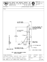
Legend to Drawing
A - Machine water inlet 3/4" NPT, 180°F water min. Hi-temp,
minimum flow requirements 4.7 GPM, 279 GPH
C - Electrical connection (does not include booster
heater
B -
Drain connection-1 1/2" NPT
D - Vent collar 4" wide x 16" long x 7" high-
Optional
E - Vent collar - standard both ends
*F -
Incoming low pressure steam connection, 3/4" NPT
(gate valve supplied)-
Requires 60 lbs of steam per hour
*G - Condensate return connection, 3/4" NPT (return to
boiler feeder of open drain)
*Steam tank heat option only.
Note: All vertical dimensions are +/- 1/2" from floor due
Note: Utility connections are identical regardless of
direction of flow.
Left to Right or Right to Left
23"
7"
W/Doors
Open
4 1/2"
67"
7/8"
Drive
Unit
Left Side
Drive
Unit
Front View
84"
75 1/2"
60
1/4"
62 1/2"
34"
29"
8"
10"
7"
5"
22"
10"
4"
6"
6 1/2"
4"
54"
70"
"X"
Table to Table
Overall
A
B
G
B
A
D
E
F
C
25"
Opening
1"
21"
Opening
25"
12"
1"
34"
Right Side
21"
6 1/2"
5"
B
A
C
8"
4 1/2"
8"
4"
62"
10 1/2"
21" Opening
70"
4" wide x 16" long cutout in
Vent Cowl/Splash Shield.
Shipped with Cover Plate.
Floor Sink Or Drain With
3" Minimum Drain Line
12 1/2"
25"
54"
Table to Table
Table Turndown
Flange 3/4" Max
3/4"
21"
Rack Rail Height
Above Dishtable
1/4" - 5/16"
Rack Rail
Tub
Table
Use Silicone Sealer
Between Table and
Lip of Machine to
Prevent Leakage
Recommended Table Fabrication
to adjustable bullet feet.
Note: Tub Will Accept
a Table Flange
Up to 24 7/8"
30"
12"
(1.74 BHP)
Note: Maximum overall dimension of unit is 30", which
includes drain handle and counduit. Minimum door
required. - 30" wide x 78" high.
AJ-54C Series Technical Manual 7610-002-30-91
Issued: 03-22-2006 Revised: N/A
SECTION 1: SPECIFICATION INFORMATION
AJ-54 MODEL DIMENSIONS
5

60 1/4"
4 1/2"
B
J
A
H
67 1/2"
7/8"
84"
Drive
Unit
Left Side
w/Doors
Open
75 1/2"
62 1/2"
34"
29"
Drive
Unit
7"
JH
D
C
H
D
J
A
H
G
F
E
C
10"
27 1/2"
24"
10"
Front View
4"
6"
6 1/2"
34"
Right Side
8 1/2"
10 3/8"
1"
4"
25"
Opening
6 1/8"
23"
12"
21"
Opening
25"
8"
26 1/4"
41"
76"
Table to Table
92"
Overall
8"
4 1/2"
8"
4"
84"
10 1/2"
21"
Opening
92"
4"w. x 16" lg Cutout in
Vent Cowl/Splash Shield.
Shipped with Cover Plate.
Floor Sink or Drain With
3" Minimum Drain Line
12 1/2"
25"
76"
Table to Table
Note: Tub Will Accept
a Table Flange
Up to 24 7/8"
Table Turndown
Flange 3/4" Max
3/4"
21"
Left to Right Operation Shown
Legend to Drawing
A -
Machine water inlet 3/4" NPT, 180°F Hi-temp,
minimum flow requirements 4.7 GPM, 279 GPH
B -
3/4" NPT prewash water inlet, 140°F water max
C - Drain connection-1 1/2" NPT
F - Vent collar 4" wide x 16" long x 7" high- Optional
E - Vent cowl standard
*G - Incoming low pressure steam connection, 3/4" FPT
(gate valve supplied)-
Optional
*H -
Condensate return connection, 3/4" FPT (return to
boiler feeder or open drain)
J -
Cold water thermostat plumbing connection 3/4"
NPT- Optional
*
Steam tank heat option only
Note: All vertical dimensions are +/- 1/2" from floor due
to adjustable bullet feet
Recommended Table Fabrication
Rack Rail Height
Above Dishtable
1/4" - 5/16"
Rack Rail
Tub
Table
Use Silicone Sealer
Between Table and
Lip of Machine to
Prevent Leakage
Prewash Plan View
Section With Cold
Water Thermostat
18 1/4"
18 3/4"
J
H
D - Electrical connection - does not include booster heater
AB
26 3/4"
24"
AJ-54C Series Technical Manual 7610-002-30-91
Issued: 03-22-2006 Revised: N/A
SECTION 1: SPECIFICATION INFORMATION
AJ-76 MODEL (LEFT TO RIGHT) DIMENSIONS
6

Right to Left Operation Shown
10"
60 1/4"
Left Side
75 1/2"
62 1/2"
34"
29"
Drive
Unit
7"
A
J
D
C
H
G
F
E
10"
Front View
4"
6"
6 1/2"
Right Side
4"
24 3/4"
8"
42"
76"
Table to Table
92"
Overall
27 1/2"
24"
8"
4 1/2"
8"
4"
84"
10 1/2"
21" Opening
92"
4"w. x 16" lg Cutout in
Vent Cowl/Splash Shield.
Shipped with Cover Plate.
Floor Sink or Drain With
3" Minimum Drain Line
12 1/2"
25"
76"
Table to Table
Note: Tub Will Accept
a Table Flange
Up to 24 7/8"
Table Turndown
Flange 3/4" Max
3/4"
21"
Legend to Drawing
Recommended Table Fabrication
Rack Rail Height
Above Dishtable
1/4" - 5/16"
Rack Rail
Tub
Table
Use Silicone Sealer
Between Table and
Lip of Machine to
Prevent Leakage
Prewash Plan View
Section With Cold
Water Thermostat
18 1/4"
18 3/4"
J
H
D
J
A
H
C
34"
8 1/2"
10 3/8"
1"
25"
Opening
6 1/8"
12"
21"
Opening
25"
4 1/2"
B
J
A
H
67 1/2"
7/8"
84"
Drive
Unit
w/Doors
Open
A -
Machine water inlet 3/4" NPT, 180°F Hi-temp,
minimum flow requirements 4.7 GPM, 279 GPH
B -
3/4" NPT prewash water inlet, 140°F water max
C - Drain connection-1 1/2" NPT
F - Vent collar 4" wide x 16" long x 7" high-
Optional
E - Vent cowl standard
*G - Incoming low pressure steam connection, 3/4" FPT
(gate valve supplied)-
Optional
*H -
Condensate return connection, 3/4" FPT (return to
boiler feeder or open drain)
J -
Cold water thermostat plumbing connection 3/4"
NPT-
Optional
*
Steam tank heat option only
Note: All vertical dimensions are +/- 1/2" from floor due
to adjustable bullet feet
D - Electrical connection - does not include booster heater
H
41"
24"
24 1/4"
B
AJ-54C Series Technical Manual 7610-002-30-91
Issued: 03-22-2006 Revised: N/A
SECTION 1: SPECIFICATION INFORMATION
AJ-76 MODEL (RIGHT TO LEFT) DIMENSIONS
7

84"
w/Doors
Open
60 1/4"
Drive
Unit
Left Side
67 1/2"
29"
Drive
Unit
7"
B
A
D
C
H
G
F
E
10"
10"
Front View
Right Side
Opening
Opening
8"
16"
38"
411/2"
B
A
12"
1"
9"
C
8"
4 1/2"
8"
4"
98"
10 1/2"
21"
Opening
106"
4"w. x 16" lg Cutout in
Vent Cowl/Splash Shield.
Shipped with Cover Plate.
Floor Sink or Drain With
3" Minimum Drain Line
12 1/2"
25"
90"
Table to Table
Note: Tub Will Accept
a Table Flange
Up to 24 7/8"
Table Turndown
Flange 3/4" Max
3/4"
21"
Left to Right Operation Shown
Legend to Drawing
A -
Machine water inlet 3/4" NPT, 180°F Hi-temp,
minimum flow requirements 4.7 GPM, 279 GPH
B - 3/4" NPT prewash water inlet, 140°F water max
C - Drain connection-1 1/2" NPT
F - Vent collar 4" wide x 16" long x 7" high- Optional
E - Vent cowl standard
*G - Incoming low pressure steam connection, 3/4" FPT
(gate valve supplied)- Optional
*H - Condensate return connection, 3/4" FPT (return to
boiler feeder or open drain)
J -
Cold water thermostat plumbing connection 3/4"
NPT- Optional
*
Steam tank heat option only
Note: All vertical dimensions are +/- 1/2" from floor due
to adjustable bullet feet
Recommended Table Fabrication
Rack Rail Height
Above Dishtable
1/4" - 5/16"
Rack Rail
Tub
Table
Use Silicone Sealer
Between Table and
Lip of Machine to
Prevent Leakage
Prewash Plan View
Section With Cold
Water Thermostat
18 1/4"
18 3/4"
J
H
D - Electrical connection - does not include booster heater
90"
Table to Table
106"
Overall
15"
8"
30"
47"
16"
12"
4"
25"
21"
2"
25"
75 1/2"
67"
62 1/2"
34"
4"
8"
6 1/2"
6"
AJ-54C Series Technical Manual 7610-002-30-91
Issued: 03-22-2006 Revised: N/A
SECTION 1: SPECIFICATION INFORMATION
AJ-90 MODEL (LEFT TO RIGHT) DIMENSIONS
8

Right to Left Operation Shown
16"
84"
w/Doors
Open
34"
60 1/4"
B
A
67"
Drive
Unit
Left Side
75 1/2"
62 1/2"
67 1/2"
29"
7"
D
A
C
H
G
10"
10"
Front View
4"
6"
6 1/2"
Right Side
2"
25"
Opening
15"
21"
Opening
25"
8"
8"
47"
90"
Table to Table
106"
Overall
F
E
16"
12"
1"
9"
C
38"
41 1/2"
12"
30"
4 1/2"
B
8"
4 1/2"
8"
4"
98"
10 1/2"
21" Opening
106"
4"w. x 16" lg Cutout in
Vent Cowl/Splash Shield.
Shipped with Cover Plate.
Floor Sink or Drain With
3" Minimum Drain Line
12 1/2"
25"
90"
Table to Table
Note: Tub Will Accept
a Table Flange
Up to 24 7/8"
Table Turndown
Flange 3/4" Max
3/4"
21"
Legend to Drawing
A -
Machine water inlet 3/4" NPT, 180°F Hi-temp,
minimum flow requirements 4.7 GPM, 279 GPH
B -
3/4" NPT prewash water inlet, 140°F water max
C - Drain connection-1 1/2" NPT
F - Vent collar 4" wide x 16" long x 7" high- Optional
E - Vent cowl standard
*G - Incoming low pressure steam connection, 3/4" FPT
(gate valve supplied)-
Optional
*H - Condensate return connection, 3/4" FPT (return to
boiler feeder or open drain)
J -
Cold water thermostat plumbing connection 3/4"
NPT-
Optional
*
Steam tank heat option only
Note: All vertical dimensions are +/- 1/2" from floor due
to adjustable bullet feet
Recommended Table Fabrication
Rack Rail Height
Above Dishtable
1/4" - 5/16"
Rack Rail
Tub
Table
Use Silicone Sealer
Between Table and
Lip of Machine to
Prevent Leakage
Prewash Plan View
Section With Cold
Water Thermostat
18 1/4"
18 3/4"
J
H
D - Electrical connection - does not include booster heater
Drive
Unit
AJ-54C Series Technical Manual 7610-002-30-91
Issued: 03-22-2006 Revised: N/A
SECTION 1: SPECIFICATION INFORMATION
AJ-90 MODEL (RIGHT TO LEFT) DIMENSIONS
9

AJ-54C Series Technical Manual 7610-002-30-91
Issued: 03-22-2006 Revised: N/A
SECTION 1: SPECIFICATION INFORMATION
SIDE LOADER (LEFT TO RIGHT) DIMENSIONS
10
**23”
CONVEYOR
DISHWASHER
LENGTH
*8”
4 1/2”
MINIMUM
25”
DISHWASHER
5”
12 1/2”
14 1/2”
29”
1 1/2” TABLE
ROLL
20 3/4”
OPENING
1”
A A
1/2”
MINIMUM
1/2”
DISHTABLE
USE SILICONE
BETWEEN
TABLE AND LIP
OF SIDE
LOADER TO
PREVENT LEAK-
AGE.
WALL OF SIDE
LOADER
SECTION “A-A”
CENTER-LINE
DISHMACHINE
SPLASH SHIELD
VENT CONNECTION
OPENING
1 1/2” DRAIN. CONNECTED
TO DISHMACHINE DRAIN
LINE
CONVEYOR
DISHMACHINE
* - 15” for 30” Model
** - 30” for 30” Model

AJ-54C Series Technical Manual 7610-002-30-91
Issued: 03-22-2006 Revised: N/A
SECTION 1: SPECIFICATION INFORMATION
SIDE LOADER (RIGHT TO LEFT) DIMENSIONS
11
14 1/2”
29”
*8”
**23”
CONVEYOR
DISHMACHINE
LENGTH
4 1/2”
MINIMUM
12 1/2”
25”
DISHWASHER
5”
1 1/2” TABLE
ROLL
20 3/4”
OPENING
1”
1/2”
MINIMUM
DISHTABLE
1/2”
WALL OF SIDE
LOADER
USE SILICONE
BETWEEN TABLE
AND LIP OF SIDE
LOADER TO PRE-
VENT LEAKAGE
SECTION “A-A”
CONVEYOR
DISHMACHINE
CENTER LINE
DISHMACHINE
VENT CONNECTION
OPENING
SPLASH
SHIELD
AA
1 1/2” DRAIN. CONNECTED TO
DISHMACHINE DRAIN LINE
* - 15” for 30” Model
** - 30” for 30” Model

AJ-54C Series Technical Manual 7610-002-30-91
Issued: 03-22-2006 Revised: N/A
SECTION 1: SPECIFICATION INFORMATION
SIDE LOADER INSTALLATION DIMENSIONS
12
Refer to chart above.
34”
23” or 30”
10”
4”
23” SIDE LOADER DIMENSIONS
30” SIDE LOADER DIMENSIONS
MODEL
AJ-54
AJ-76
AJ-90
MODEL
AJ-54
AJ-76
AJ-90
DIMENSIONS
85”
107”
121”
DIMENSIONS
92”
114”
128”
(Left to Right installation shown for reference.)
NOTE: ALL DIMENSIONS ARE TYPICAL.
Depending on the width of the
side loader.
/