Issue 06/2020 Art. No. 7001-0402
Operating Manual
CB-S / CB-S-UL (E7)
CO
2
Incubator
with FPI-sensor system and RD4 controller
Model Model version Art. No.
CB-S 170 CBS170-230V 9040-0189, 9140-0189
CB-S 170-UL CBSUL170-120V 9040-0190, 9140-0190
CB-S 260 CBS260-230V 9040-0191, 9140-0191
CB-S 260-UL CBSUL260-120V 9040-0192, 9140-0192
BINDER GmbH
Address: Post office box 102, 78502 Tuttlingen, Germany Phone: +49 7462 2005 0
Fax: +49 7462 2005 100 Internet: http://www.binder-world.com
E-mail: info@binder-world.com Service Hotline: +49 7462 2005 555
Service Fax: +49 7462 2005 93 555 Service E-Mail: service@binder-world.com
Service Hotline USA: +1 866 885 9794 or +1 631 224 4340 x3
Service Hotline Asia Pacific: +852 390 705 04 or +852 390 705 03
Service Hotline Russia and CIS: +7 495 988 15 16

CB-S / CB-S-UL (E7) 06/2020 page 2/119
Contents
1. SAFETY .................................................................................................................. 6
1.1 Personnel Qualification ....................................................................................................................... 6
1.2 Operating manual ................................................................................................................................ 6
1.3 Legal considerations ........................................................................................................................... 6
1.4 Structure of the safety instructions ...................................................................................................... 7
1.4.1 Signal word panel ..................................................................................................................... 7
1.4.2 Safety alert symbol ................................................................................................................... 7
1.4.3 Pictograms ................................................................................................................................ 8
1.4.4 Word message panel structure ................................................................................................. 8
1.5 Localization / position of safety labels at the chamber ....................................................................... 9
1.6 Type plate.......................................................................................................................................... 10
1.7 General safety instructions on installing and operating the chamber ............................................... 11
1.8 Precautions when working with CO
2
gas .......................................................................................... 13
1.9 Precautions when handling gas cylinders ......................................................................................... 13
1.10 Intended use ..................................................................................................................................... 14
1.11 Foreseeable Misuse .......................................................................................................................... 15
1.12 Residual Risks .................................................................................................................................. 16
1.13 Operating instructions ....................................................................................................................... 17
1.14 Measures to prevent accidents ......................................................................................................... 18
2. CHAMBER DESCRIPTION .................................................................................. 19
2.1 Chamber overview ............................................................................................................................ 20
2.2 Inner chamber ................................................................................................................................... 21
2.3 Connection panel on the rear of the chamber................................................................................... 22
2.4 Chamber doors ................................................................................................................................. 23
2.5 Instrument panel ............................................................................................................................... 23
3. COMPLETENESS OF DELIVERY, TRANSPORTATION, STORAGE, AND
INSTALLATION .................................................................................................... 24
3.1 Unpacking, and checking equipment and completeness of delivery ................................................ 24
3.2 Guidelines for safe lifting and transportation ..................................................................................... 25
3.3 Storage .............................................................................................................................................. 25
3.4 Location of installation and ambient conditions ................................................................................ 25
4. INSTALLATION AND CONNECTIONS ............................................................... 28
4.1 Shelves .............................................................................................................................................. 28
4.2 CO
2
sensor ........................................................................................................................................ 28
4.2.1 Connecting the CO
2
sensor .................................................................................................... 28
4.2.2 General notes ......................................................................................................................... 28
4.3 Water pan .......................................................................................................................................... 29
4.4 Gas connection ................................................................................................................................. 30
4.4.1 Connecting the CO
2
gas cylinder ............................................................................................ 31
4.4.2 Connecting the gas hose to the chamber rear ....................................................................... 32
4.4.3 Gas cylinder connection kit (option) ........................................................................................ 33
4.5 Electrical connection ......................................................................................................................... 34
5. FUNCTIONAL OVERVIEW OF THE RD4 CHAMBER CONTROLLER ............... 35
5.1 Menu structure of the controller and access levels ........................................................................... 36
5.2 Performance during and after power failures and shut down ........................................................... 37
6. START UP ............................................................................................................ 37
6.1 Turning on the chamber .................................................................................................................... 37
6.2 Preset factory parameters ................................................................................................................. 38
6.3 Performance after turning on the chamber ....................................................................................... 38
6.4 Altitude of the installation site above sea level ................................................................................. 39

CB-S / CB-S-UL (E7) 06/2020 page 3/119
7. TEMPERATURE AND CO
2
SET-POINT ENTRY ................................................. 40
7.1 Temperature set-point entry .............................................................................................................. 40
7.2 CO
2
set-point entry ............................................................................................................................ 40
8. PLACING SAMPLES IN THE INCUBATOR ........................................................ 41
9. SETTING SPECIAL CONTROLLER FUNCTIONS .............................................. 42
9.1 Idle mode........................................................................................................................................... 42
9.2 Deactivated CO
2
control .................................................................................................................... 43
10. PASSWORD ......................................................................................................... 43
10.1 Password request ............................................................................................................................. 43
10.2 Assign and modify a password ......................................................................................................... 44
10.2.1 Assign and modify the User password ................................................................................... 44
10.2.2 Assign and modify the Admin password ................................................................................. 44
11. TEMPERATURE SAFETY DEVICES ................................................................... 45
11.1 Over temperature protective device (class 1) ................................................................................... 45
11.2 Overtemperature safety controller class 3.1 ..................................................................................... 45
11.2.1 Setting the safety controller mode .......................................................................................... 46
11.2.2 Setting the safety controller value ........................................................................................... 46
11.2.3 Message and measures in the state of alarm ......................................................................... 47
11.2.4 Function check ........................................................................................................................ 47
12. GENERAL CONTROLLER SETTINGS ................................................................ 48
12.1 Selecting the controller’s menu language ......................................................................................... 48
12.2 Selecting the temperature unit .......................................................................................................... 48
12.3 Setting the current date ..................................................................................................................... 49
12.4 Setting the current time ..................................................................................................................... 50
12.5 Function “Language selection at restart” .......................................................................................... 50
12.6 Setting the chamber address ............................................................................................................ 51
12.7 Display brightness ............................................................................................................................. 51
13. TOLERANCE RANGE SETTINGS ....................................................................... 52
13.1 Setting the delay time for tolerance range alarm .............................................................................. 52
13.2 Setting the temperature tolerance range .......................................................................................... 52
13.3 Setting the CO
2
tolerance range ....................................................................................................... 53
13.4 Setting the delay time for door open alarm ....................................................................................... 53
14. CHAMBER SETTINGS (FOR EXPERIENCED USERS ONLY) ........................... 54
14.1 Setting the humidity control ............................................................................................................... 54
14.2 Setting the door heating offset .......................................................................................................... 54
14.3 Adjusting the heating power – for BINDER Service only .................................................................. 55
15. NOTIFICATION AND ALARM FUNCTIONS ........................................................ 55
15.1 Alarm messages ............................................................................................................................... 55
15.2 Information messages ....................................................................................................................... 57
15.3 Activating / deactivating the audible alarm (alarm buzzer) ............................................................... 58
15.4 Measures in case of alarm ................................................................................................................ 58
15.4.1 Door open alarm ..................................................................................................................... 58
15.4.2 Safety controller temperature alarm ....................................................................................... 58
15.4.3 Temperature tolerance range alarm (overtemperature / too low temperature) ...................... 59
15.4.4 CO
2
tolerance range alarm (CO
2
over/under concentration) .................................................. 60
15.4.5 CO
2
pressure alarm ................................................................................................................ 60
15.4.6 Power failure alarm ................................................................................................................. 61
15.4.7 Alarms referring to temperature sensor failures ..................................................................... 62
15.4.8 Alarms referring to CO
2
sensor failure .................................................................................... 63
15.4.9 Alarm on ineffective sterilization ............................................................................................. 63
15.5 Zero-voltage relay alarm output ........................................................................................................ 64

CB-S / CB-S-UL (E7) 06/2020 page 4/119
16. ETHERNET NETWORK SETTINGS .................................................................... 65
16.1 Showing the network settings ........................................................................................................... 65
16.1.1 Showing the chamber‘s MAC address .................................................................................... 65
16.1.2 Showing the IP address .......................................................................................................... 65
16.1.3 Showing the subnet mask ....................................................................................................... 66
16.1.4 Showing the standard gateway ............................................................................................... 66
16.1.5 Showing the DNS server address ........................................................................................... 66
16.1.6 Showing the DNS chamber name .......................................................................................... 67
16.2 Changing the configuration of the network settings .......................................................................... 67
16.2.1 Selecting the type of IP address assignment (automatic / manual) ....................................... 67
16.2.2 Selecting the type of assignment of the DNS server address (automatic / manual) .............. 68
16.2.3 Assigning the IP address ........................................................................................................ 68
16.2.4 Setting the subnet mask ......................................................................................................... 69
16.2.5 Setting the standard gateway ................................................................................................. 69
16.2.6 Assigning the DNS server address ......................................................................................... 70
17. DATA RECORDER .............................................................................................. 70
17.1 Recorded data ................................................................................................................................... 70
17.2 Storage capacity ............................................................................................................................... 71
17.3 Setting the storage rate for the “DL1” recorder data ......................................................................... 71
17.4 Deleting the data recorder................................................................................................................. 71
18. USB MENU: DATA TRANSFER VIA USB INTERFACE ..................................... 72
18.1 Connecting the USB stick ................................................................................................................. 72
18.2 Import function .................................................................................................................................. 73
18.3 Export functions ................................................................................................................................ 73
18.4 Ongoing data transfer ....................................................................................................................... 74
18.5 Error during data transmission .......................................................................................................... 74
18.6 Removing the USB stick ................................................................................................................... 74
19. REFERENCE MEASUREMENTS ........................................................................ 75
19.1 CO
2
reference measuring ................................................................................................................. 75
19.1.1 Measuring the CO
2
concentration indirectly via the pH of the cell medium ............................ 75
19.1.2 Measuring CO
2
directly via chemical indicator tubes.............................................................. 76
19.1.3 Measuring CO
2
directly with an electronic infrared measuring device ................................... 77
19.2 Temperature reference measurement .............................................................................................. 77
20. OPTIONS .............................................................................................................. 77
20.1 Silicone access ports 30 mm / 1.18 in, closable with 2 silicone plugs (8012-0558 rear, 8012-0559
left, 8012-0560 right) (option) ............................................................................................................ 77
20.2 Base on castors (option) ................................................................................................................... 78
20.3 Flat stacking frame (option)............................................................................................................... 78
20.4 APT-COM™ 4 Multi Management Software (option) ........................................................................ 78
20.5 Data logger kit (option) ...................................................................................................................... 78
20.6 Analog outputs for temperature and CO
2
(option) ............................................................................ 79
21. AVOIDING MICROBIAL CONTAMINATION........................................................ 79
21.1 Cells and media ................................................................................................................................ 79
21.2 Laboratory conditions / equipment around the CO
2
incubator .......................................................... 79
21.3 Working and behavior in the lab ....................................................................................................... 80
21.4 Chamber design and equipment ....................................................................................................... 80
21.5 Handling the CO
2
incubator .............................................................................................................. 81
22. CLEANING, DECONTAMINATION / DISINFECTION, AND STERILIZATION .... 82
22.1 Cleaning ............................................................................................................................................ 83
22.2 Decontamination / chemical disinfection of the chamber .................................................................. 84
22.3 Disinfection of the CO
2
sensor .......................................................................................................... 85

CB-S / CB-S-UL (E7) 06/2020 page 5/119
23. HOT-AIR STERILIZATION AT 180 °C / 356 °F .................................................... 86
23.1 Overview ........................................................................................................................................... 86
23.2 Performing a hot-air sterilization ....................................................................................................... 87
23.2.1 Preparations for hot-air sterilization ........................................................................................ 87
23.3 Starting and running the hot-air sterilization cycle ............................................................................ 88
23.3.1 Starting sterilization ................................................................................................................. 88
23.3.2 Performance during sterilization ............................................................................................. 89
23.3.3 Completing the entire sterilization cycle ................................................................................. 89
23.4 Prematurely terminating the sterilization cycle – effects ................................................................... 90
23.4.1 Premature termination after less than 6 hours: Ineffective sterilization .................................. 90
23.4.2 Premature termination after more than 6 hours, i.e., during the cooling-down phase:
successful sterilization ............................................................................................................ 91
23.5 Prematurely terminating the sterilization cycle – procedure ............................................................. 91
23.5.1 Cancelling sterilization via the controller menu ...................................................................... 91
23.5.2 Opening the outer door ........................................................................................................... 92
23.5.3 Turning off the chamber .......................................................................................................... 92
24. MAINTENANCE, AND SERVICE, TROUBLESHOOTING, REPAIR, TESTING .. 93
24.1 General information, personnel qualification..................................................................................... 93
24.2 Maintenance intervals, service .......................................................................................................... 94
24.3 Service Reminder .............................................................................................................................. 94
24.4 Gas inlet fine filter ............................................................................................................................. 95
24.5 Simple troubleshooting ...................................................................................................................... 95
24.5.1 General ................................................................................................................................... 95
24.5.2 Temperature ........................................................................................................................... 96
24.5.3 CO
2
......................................................................................................................................... 97
24.5.4 Humidity .................................................................................................................................. 98
24.5.5 Controller ................................................................................................................................ 98
24.5.6 Sterilization ............................................................................................................................. 98
24.6 Sending the chamber back to BINDER GmbH ................................................................................. 99
25. DISPOSAL.......................................................................................................... 100
25.1 Disposal of the transport packing .................................................................................................... 100
25.1.1 Outer chamber packing......................................................................................................... 100
25.1.2 Packing inside the chamber, equipment ............................................................................... 100
25.2 Decommissioning ............................................................................................................................ 101
25.3 Disposal of the chamber in the Federal Republic of Germany ....................................................... 101
25.4 Disposal of the chamber in the member states of the EU except for the Federal Republic of
Germany................................................................
.......................................................................... 102
25.5 Disposal of the chamber in non-member states of the EU ............................................................. 103
26. TECHNICAL DESCRIPTION .............................................................................. 104
26.1 Factory calibration and adjustment ................................................................................................. 104
26.2 Over current protection ................................................................................................................... 104
26.3 Definition of usable volume ............................................................................................................. 104
26.4 CB-S / CB-S-UL technical data ....................................................................................................... 105
26.5 Important conversion data for non-SI units ..................................................................................... 106
26.6 Conversion table for gas inlet pressures, bar – psi ......................................................................... 107
26.7 Equipment and options (extract) ..................................................................................................... 107
26.8 Options, accessories, and spare parts (extract) ............................................................................. 108
26.9 Dimensions...................................................................................................................................... 109
27. CERTIFICATES AND DECLARATIONS OF CONFORMITY ............................. 111
27.1 EU Declaration of Conformity.......................................................................................................... 111
28. PRODUCT REGISTRATION .............................................................................. 113
29. CONTAMINATION CLEARANCE CERTIFICATE ............................................. 114
29.1 For chambers located outside the USA and Canada ..................................................................... 114
29.2 For chambers in the USA and Canada ........................................................................................... 117

CB-S / CB-S-UL (E7) 06/2020 page 6/119
Dear Customer,
For the correct operation of the CO
2
incubator CB-S / CB-S-UL, it is important that you read this operating
manual completely and carefully and observe all instructions as indicated. Failure to read, understand
and follow the instructions may result in personal injury. It can also lead to damage to the chamber and/or
poor equipment performance.
1. Safety
1.1 Personnel Qualification
The chamber must only be installed, tested, and started up by personnel qualified for assembly, startup,
and operation of the chamber. Qualified personnel are persons whose professional education,
knowledge, experience and knowledge of relevant standards allow them to assess, carry out, and identify
any potential hazards in the work assigned to them. They must have been trained and instructed, and be
authorized, to work on the chamber.
The chamber should only be operated by laboratory personnel especially trained for this purpose and
familiar with all precautionary measures required for working in a laboratory. Observe the national regula-
tions on minimum age of laboratory personnel.
1.2 Operating manual
This operating manual is part of the components of delivery. Always keep it handy for reference in the
vicinity of the chamber. If selling the unit, hand over the operating manual to the purchaser.
To avoid injuries and damage observe the safety instructions of the operating manual. Failure to follow
instructions and safety precautions can lead to significant risks.
DANGER
Dangers due to failure to observe the instructions and safety precautions.
Serious injuries and chamber damage. Risk of death.
Observe the safety instructions in this Operating Manual.
Follow the operating procedures in this Operating Manual.
Carefully read the complete operating instructions of the chamber prior to installing and
using the chamber.
Keep the operating manual for future reference
Make sure that all persons who use the chamber and its associated work equipment have
read and understood the Operating Manual.
This Operating Manual is supplemented and updated as needed. Always use the most recent version of
the Operating Manual. When in doubt, call the BINDER Service Hotline for information on the up-to-
dateness and validity of this Operating Manual.
1.3 Legal considerations
This operating manual is for informational purposes only. It contains information for correct and safe in-
stalling, start-up, operation, decommissioning, cleaning and maintenance of the product. Note: the con-
tents and the product described are subject to change without notice.
Understanding and observing the instructions in this operating manual are prerequisites for hazard-free
use and safety during operation and maintenance. Images are to provide basic understanding. They may
deviate from the actual version of the chamber. The actual scope of delivery can, due to optional or spe-
cial design, or due to recent technical changes, deviate from the information and illustrations in these
instructions this operating manual.

CB-S / CB-S-UL (E7) 06/2020 page 7/119
In no event shall BINDER be held liable for any damages, direct or incidental arising out of or related to
the use of this manual.
This operating manual cannot cover all conceivable applications. If you would like additional information,
or if special problems arise that are not sufficiently addressed in this manual, please ask your dealer or
contact us directly, e.g. by phone at the number located on page one of this manual
Furthermore, we emphasize that the contents of this operating manual are not part of an earlier or exist-
ing agreement, description, or legal relationship, nor do they modify such a relationship. All obligations on
the part of BINDER derive from the respective purchase contract, which also contains the entire and ex-
clusively valid statement of warranty administration and the general terms and conditions, as well as the
legal regulations valid at the time the contract is concluded. The statements in this manual neither aug-
ment nor restrict the contractual warranty provisions.
1.4 Structure of the safety instructions
In this operating manual, the following safety definitions and symbols indicate dangerous situations in
accordance with the standards ISO 3864-2 and ANSI Z535.6.
1.4.1 Signal word panel
Depending on the seriousness and probability of serious consequences, potential dangers are identified
with a signal word, the corresponding safety color, and if appropriate, the safety alert symbol.
DANGER
Indicates an imminently hazardous situation that, if not avoided, will result in death or serious
(irreversible) injury.
WARNING
Indicates a potentially hazardous situation which, if not avoided, could result in death or serious
(irreversible) injury
CAUTION
Indicates a potentially hazardous situation which, if not avoided, may result in moderate or minor
(reversible) injury
NOTICE
Indicates a potentially hazardous situation which, if not avoided, may result in damage to the product
and/or its functions or of a property in its proximity.
1.4.2 Safety alert symbol
Use of the safety alert symbol indicates a risk of injury.
Observe all measures that are marked with the safety alert symbol in order to avoid death or
injury.

CB-S / CB-S-UL (E7) 06/2020 page 8/119
1.4.3 Pictograms
Warning signs
Electrical hazard
Hot surface
Explosive Atmosphere
Stability hazard
Lifting hazard
Gas cylinders
CO
2
suffocation and
poisoning hazard
Pollution Hazard
Harmful substances
Biohazard
Risk of corrosion and /
or chemical burns
Mandatory action signs
Mandatory regulation
Read operating
instructions
Disconnect the power
plug
Lift with several persons
Environment protection
Wear protective gloves
Wear safety goggles
Prohibition signs
Do NOT touch
Do NOT spray with
water
Do NOT climb
Information to be observed in order to ensure optimum function of the product.
1.4.4 Word message panel structure
Type / cause of hazard.
Possible consequences.
∅ Instruction on how to avoid the hazard: prohibition
Instruction on how to avoid the hazard: mandatory action
Observe all other notes and information not necessarily emphasized in the same way, in order to avoid
disruptions that could result in direct or indirect injury or property damage.

CB-S / CB-S-UL (E7) 06/2020 page 9/119
1.5 Localization / position of safety labels at the chamber
The following labels are located on the chamber:
Pictograms (Warning signs)
Service label
Hot surface
Risk of injury (UL chambers only).
Observe the safety instructions in the
operating manual.
Figure 1: Position of labels
on the CO
2
incubator CB-S
Figure 2: Position of labels
on the CO
2
incubator CB-S-UL
Keep safety labels complete and legible.
Replace safety labels that are no longer legible. Contact BINDER Service for these replacements.

CB-S / CB-S-UL (E7) 06/2020 page 10/119
1.6 Type plate
Position of type plate: left chamber side (seen from front), at the bottom in the middle.
Figure 3: Position of type plate
Figure 4: Type plate (example CB-S 170 standard chamber, 9040-0189)
Indications of the type plate
(example)
Information
BINDER
Manufacturer: BINDER GmbH
CB-S 170
Model designation
CO2 Incubator
Device name: CO
2
Incubator
Serial No.
000000000000
Serial No. of the chamber
Built
2020
Year of construction
Nominal temperature
190 °C
374 °F
Nominal temperature
IP protection
20
Type of IP protection acc. to standard EN 60529
Temp. safety device
DIN 12880
Temperature safety device acc. to standard DIN 12880:2007
Class
3.1
Class of temperature safety device
Art. No.
9040-0189
Art. No. of the chamber
Project No.
---
Optional: Special application acc. to project no.
1,30 kW
Nominal power
6,1 A
Nominal current
200-230 V / 50 Hz
Nominal voltage range +/- 10%
at the indicated power frequency
200-230 V / 60 Hz
1 N ~
Current type
Nominal temp.
190 °C
1,30 kW / 6,1 A
374 °F
200-230 V / 50 Hz
IP protection
20
200-230 V / 60 Hz
Safety device
DIN 12880
1 N ~
Class
3.1
Art. No.
9040-0189
Project No.
Built
2020
CO2 Incubator
BINDER GmbH
Im Mittleren Ösch 5
78532 Tuttlingen / Germany
www.binder-world.com
CB-S 170
E7
Serial No. 00000000000000
Made in Germany

CB-S / CB-S-UL (E7) 06/2020 page 11/119
Symbol on the type plate
Information
CE conformity marking
Electrical and electronic equipment manufactured / placed on
the market in the EU after 13 August 2005 and to be disposed of
in a separate collection according to Directive 2012/19/EU on
waste electrical and electronic equipment (WEEE).
1.7 General safety instructions on installing and operating the chamber
With regard to operating the chamber and to the installation location, please observe the local and na-
tional regulations relevant for your country (for Germany: DGUV guidelines 213-850 on safe working in
laboratories, issued by the employers’ liability insurance association).
BINDER GmbH is only responsible for the safety features of the chamber provided skilled electricians or
qualified personnel authorized by BINDER perform all maintenance and repair, and if components relat-
ing to chamber safety are replaced in the event of failure with original spare parts.
To operate the chamber, use only original BINDER accessories or accessories from third-party suppliers
authorized by BINDER. The user is responsible for any risk caused by using unauthorized accessories.
NOTICE
Danger of overheating due to lack of ventilation.
Damage to the chamber.
∅ Do NOT install the chamber in unventilated recesses.
Ensure sufficient ventilation for dispersal of the heat.
Observe the prescribed minimum distances when installing the chamber (chap.3.4).
Do not install or operate the chamber in hazardous locations.
DANGER
Danger of explosion due to combustible dusts or explosive mixtures in the vicinity
of the chamber.
Serious injury or death from burns and / or explosion pressure.
∅ Do NOT operate the chamber in potentially explosive areas.
KEEP combustible dust or air-solvent mixtures AWAY from the chamber.
The chamber does not dispose of any measures of explosion protection.
DANGER
Danger of explosion due to introduction of flammable or explosive substances in
the chamber.
Serious injury or death from burns and / or explosion pressure.
∅ Do NOT introduce any substance into the chamber which is combustible or explosive at
working temperature.
∅ Do NOT introduce any combustible dust or air-solvent mixture in the inner chamber.
Any solvent contained in the charging material must not be explosive or inflammable. I.e., irrespective of
the solvent concentration in the steam room, NO explosive mixture with air must form. The temperature
inside the chamber must lie below the flash point or below the sublimation point of the charging material.
Familiarize yourself with the physical and chemical properties of the charging material, as well as the
contained moisture constituent and its behavior with the addition of heat energy and humidity.

CB-S / CB-S-UL (E7) 06/2020 page 12/119
Familiarize yourself with any potential health risks caused by the charging material, the contained mois-
ture constituent or by reaction products that may arise during the temperature process. Take adequate
measures to exclude such risks prior to putting the CO
2
incubator into operation.
DANGER
Electrical hazard by water entering the chamber.
Deadly electric shock.
∅ The chamber must NOT become wet during operation, cleaning, or maintenance.
∅ Do NOT install the chamber in damp areas or in puddles.
Set up the chamber in a splash-proof manner.
The chambers were produced in accordance with VDE regulations and were routinely tested in accord-
ance to VDE 0411-1 (IEC 61010-1).
During and after a sterilization the temperature of the inner surfaces almost equals the set-point. The
glass door, the glass door handle, and the inner chamber will become hot during a sterilization.
CAUTION
Danger of burning by touching hot chamber parts during or after a sterilization.
Burns.
∅ Do NOT touch the glass door, the glass door handle, the inner surfaces, and door gas-
kets during or after a sterilization.
WARNING
Danger of injury and damages by the chamber tipping over.
Injuries and damage to the chamber and the charging material
∅ Do NOT load the chamber door with heavy objects while it is open.

CB-S / CB-S-UL (E7) 06/2020 page 13/119
1.8 Precautions when working with CO
2
gas
Carbon dioxide (CO
2
) in high concentrations is hazardous to health. It is colorless and almost odorless
and therefore practically imperceptible. Vent out any CO
2
gas that may escape via good room ventilation
or a suitable connection to an exhaust system. We recommend installing a CO
2
warning system.
DANGER
Danger of suffocation and poisoning by high concentration of CO
2
(> 4 Vol.-%).
Death by suffocation.
∅ Do NOT set up chambers in non-ventilated recesses.
Ensure technical ventilation measures.
Observe the relevant regulations for handling CO
2
.
Close the CO
2
supply when decommissioning the chamber.
1.9 Precautions when handling gas cylinders
General information for safe handling of gas cylinders:
• Store and use gas cylinders only in well-ventilated locations.
• Open the gas cylinder valve slowly to avoid pressure surges
• Secure gas cylinders during storage and use against falling (chaining).
• Transport gas cylinders with a cylinder cart, do not carry, roll, or throw them.
•
Always close the valve even with apparently empty cylinders; screw on the cap when not in
use. Return gas cylinders with the valve closed.
• Do not open gas cylinders by force. Mark them when damaged
• Protect gas cylinders against fire, e.g. do not store together with flammable liquids
• Observe relevant regulations for dealing with gas cylinders.
Secure the gas cylinders against falling and other mechanical damage.
WARNING
Risk of injury through sudden release of the stored pressure energy when the valve
safety is torn off.
Injuries.
Secure gas cylinders against falling (chaining).
Transport gas cylinders with a cylinder cart.
The valve of the gas cylinder always must be closed before screwing on or unscrewing the gas hose.
WARNING
Risk of injury through sudden release of the stored pressure energy when opening
the cylinder valve of a not connected cylinder.
Injuries.
Close the gas cylinder valve before connecting or removing the gas hose.
After connecting the gas cylinder, check all gas connections for leaks (e.g. with leak spray or
diluted soap solution).

CB-S / CB-S-UL (E7) 06/2020 page 14/119
1.10 Intended use
Observing the instructions in this operating manual and conducting regular maintenance
work (chap. 24) is part of the intended use.
Any use of the chambers that does not comply with the requirements specified in this Operating
Manual shall be considered improper use.
Other applications than those described in this chapter are not approved.
Use
CO
2
incubators CB-S / CB-S-UL are suitable for the cultivation of mammal cells under typical conditions
of approx. 37 °C / 98.6 °F. The chambers permit setting defined pH conditions by common NaHCO
3
buff-
er systems of commercial cell media by keeping an exact CO
2
atmosphere inside. The chambers guaran-
tee high humidity inside to avoid osmolarity increasing caused by the evaporation of the cell media.
The chambers are suitable for exact conditioning of harmless materials.
Requirements for the chamber load
Any solvent any solvent must not be explosive and flammable. Components of the charging material must
NOT form an explosive mixture with air. The operating temperature must lie below the flash point or be-
low the sublimation point of the charging material. Any component of the charging material must NOT be
able to release toxic gases.
The charging material shall not contain any corrosive ingredients that may damage the machine compo-
nents made of stainless steel, aluminum, and copper. Such ingredients include in particular acids and
halides. Any corrosive damage caused by such ingredients is excluded from liability by BINDER GmbH.
The chamber does not dispose of any measures of explosion protection.
DANGER
Explosion or implosion hazard and danger of poisoning through the introduction of
unsuitable loading material.
Poisoning. Serious injury or death from burns and / or explosion pressure.
∅ Do NOT introduce any substance combustible or explosive at working temperature into
the chamber, in particular no energy sources such as batteries or lithium-ion batteries.
∅ NO explosive dust or air-solvent mixture in the inner chamber.
∅ Do NOT introduce any substance which could lead to release of toxic gases.
Contamination of the chamber by toxic, infectious or radioactive substances must be prevented
WARNING
Danger of intoxication and infection through contamination of the chamber with
toxic, infectious or radioactive substances.
Damages to health.
Protect the interior of the chamber from contamination by toxic, infectious or radioactive
substances.
Take suitable protective measures when introducing and removing toxic, infectious or
radioactive material
In case of foreseeable use of the device there is no risk for the user through the integration of the cham-
ber into systems or by special environmental or operating conditions in the sense of EN 61010-1:2010.
For this, the intended use of the chamber and all its connections must be observed.

CB-S / CB-S-UL (E7) 06/2020 page 15/119
Medical devices
The chambers are not classified as medical devices as defined by the Medical Device Directive
93/42/EEC.
Due to the special demands of the Medical Device Directive (MDD), these chambers are not
qualified for sterilization of medical devices as defined by the directive 93/42/EWG.
Personnel Requirements
Only trained personnel with knowledge of the Operating Manual can set up and install the chamber, start
it up, operate, clean, and take it out of operation. Service and repairs call for further technical require-
ments (e.g. electrical know-how), as well as knowledge of the service manual.
Installation site requirements
The chambers are designed for setting up inside a building (indoor use).
The requirements described in the Operating Manual for installation site and ambient conditions (Chap.
3.4) must be met.
WARNING: If customer should use a BINDER chamber running in non-supervised continu-
ous operation, we strongly recommend in case of inclusion of irrecoverable specimen or
samples to split such specimen or samples and store them in at least two chambers, if this is
feasible.
Relevant regulations for dealing with CO
2
and gas cylinders must be observed.
1.11 Foreseeable Misuse
Other applications than those described in chap. 1.10 are not approved.
This expressly includes the following misuses (the list is not exhaustive), which pose risks despite the
inherently safe construction and existing technical safety equipment:
• Non-observance of Operating Manual
• Non-observance of information and warnings on the chamber (e.g. control unit messages, safety iden-
tifiers, warning signals)
• Installation, startup, operation, maintenance and repair by untrained, insufficiently qualified, or unau-
thorized personnel
• Missed or delayed maintenance and testing
• Non-observance of traces of wear and tear
• Insertion of materials excluded or not permitted by this Operating Manual.
• Non-compliance with the admissible parameters for processing the respective material.
• Failure to comply with the relevant regulations for handling gas cylinders
• Failure to comply with the relevant regulations for handling CO
2
• Operation of the chamber without ventilation measures
• Installation, testing, service or repair in the presence of solvents
• Installation of replacement parts and use of accessories and operating resources not specified and
authorized by the manufacturer
• Installation, startup, operation, maintenance or repair of the chamber in absence of operating instruc-
tions
• Bypassing or changing protective systems, operation of the chamber without the designated protective
systems

CB-S / CB-S-UL (E7) 06/2020 page 16/119
• Non-observance of messages regarding cleaning and disinfection of the chamber.
• Spilling water or cleaning agent on the chamber, water penetrating into the chamber during operation,
cleaning or maintenance.
• Cleaning activity while chamber is turned on.
• Operation of the chamber with a damaged housing or damaged power cord.
• Continued operation of the chamber during an obvious malfunction
• Insertion of objects, particularly metallic objects, in louvers or other openings or slots on the chamber
• Human error (e.g. insufficient experience, qualification, stress, exhaustion, laziness)
To prevent these and other risks from incorrect operation, it is recommended the operator issue operating
instructions and standard operating procedures (SOPs).
1.12 Residual Risks
The unavoidable design features of a chamber, as well as its proper field of application, can also pose
risks, even during correct operation. These residual risks include hazards which, despite the inherently
safe design, existing technical protective equipment, safety precautions and supplementary protective
measures, cannot be ruled out.
Messages on the chamber and in the Operating Manual warn of residual risks. The consequences of
these residual risks and the measures required to prevent them are listed in the Operating Manual. More-
over, the operator must take measures to minimize hazards from unavoidable residual risks. This in-
cludes, in particular, issuing operating instructions.
The following list summarizes the hazards against which this Operating Manual and the Service Manual
warn, and specifies protective measures at the appropriate spots:
Unpacking, Transport, Installation
• Sliding or tilting the chamber
• Setup of the chamber in unauthorized areas
• Installation of a damaged chamber
• Installation of a chamber with damaged power cord
• Inappropriate site of installation
• Missing protective conductor connection
Normal operation
• Assembly errors
• Contact with hot surfaces on the housing
• Contact with hot surfaces in the interior and inside of doors
• Emission of non-ionizing radiation from electrical operating resources
• Contact with live parts in normal state
Cleaning and Decontamination
• Penetration of water into the chamber
• Inappropriate cleaning and decontamination agents
• Enclosure of persons in the interior

CB-S / CB-S-UL (E7) 06/2020 page 17/119
Malfunction and Damage
• Continued operation of the chamber during an obvious malfunction or outage of the heating or gas
systems
• Contact with live parts during error status
• Operation of a unit with damaged power cord
Maintenance
• Maintenance work on live parts.
• Execution of maintenance work by untrained/insufficiently qualified personnel
• Electrical safety analysis during annual maintenance not performed
Trouble-shooting and Repairs
• Non-observance of warning messages in the Service Manual
• Trouble-shooting of live parts without specified safety measures
• Absence of a plausibility check to rule out erroneous inscription of electrical components
• Performance of repair work by untrained/insufficiently qualified personnel
• Inappropriate repairs which do not meet the quality standard specified by BINDER
• Use of replacement parts other than BINDER original replacement parts
• Electrical safety analysis not performed after repairs
1.13 Operating instructions
Depending on the application and location of the chamber, it is recommended that the operator of the
chamber provides the relevant information for safe operation of the chamber in a set of operating instruc-
tions.
Keep these operating instructions with the chamber at all times in a place where they are
clearly visible. They must be comprehensible and written in the language of the employees.

CB-S / CB-S-UL (E7) 06/2020 page 18/119
1.14 Measures to prevent accidents
The manufacturer took the following measures to prevent dangers:
• Indications on the type plate
See operating manual chap. 1.6.
• Operating manual
An operating manual is available for each chamber.
• Overtemperature monitoring
The chamber is equipped with a temperature display, which can be read from outside.
The chamber is equipped with an additional safety controller (temperature safety device class 3.1 acc.
to DIN 12880:2007). Visual and audible (buzzer) signals indicate temperature exceeding.
• Safety, measurement, and control equipment
The safety, measuring, and control equipment is easily accessible.
• Electrostatic charge
The interior parts are grounded.
• Non-ionizing radiation
Non-ionizing radiation is not intentionally produced, but released only for technical reasons by electri-
cal equipment (e.g. power cables). The machine is equipped with no permanent magnets. If persons
with active implants (e.g. pacemakers, defibrillators) keep a safe distance (distance of field source to
implant) of 30 cm, an influence of these implants can be excluded with high probability.
• Protection against touchable surfaces
Tested according to EN ISO 13732-1:2008.
• Floors
See operating manual chap. 3.4 for correct installation
• Cleaning
See operating manual chap. 22.1.

CB-S / CB-S-UL (E7) 06/2020 page 19/119
2. Chamber description
The CO
2
incubators CB-S / CB-S-UL series were produced with great care using the latest tools for de-
velopment and production. They can be operated in a temperature range from 6 °C / 10.8 °F above ambi-
ent temperature up to +50 °C / 122°F and a CO
2
range of 0 vol.-% up to 20 vol.-%. The chambers are
equipped with a microprocessor controller for temperature and CO
2
levels and a digital display accurate
to one-tenth of a degree resp. 0.1 vol.-%. They are available in different voltages.
Material: The inner chamber, the pre-heating chamber and the inside of the doors are all made of stain-
less steel V2A (German material no. 1.4301, US equivalent AISI 304). The inner surfaces are smooth and
therefore easy to clean. The inner chamber is deep-drawn from one piece, polished (suitable for pharma-
ceutical applications) and has no welds or inaccessible corners. The hinges and the seal of the inner
glass door are glued from the outside to aid cleaning of the inner chamber. When operating the chamber
at high temperatures (sterilization), the impact of the oxygen in the air may cause discoloration of the
metallic surfaces (yellowish-brown or blue) by natural oxidation processes. These colorations are harm-
less and will in no way impair the function or quality of the chamber.
The perforated shelves are also made of stainless steel (German material no. 1.4016, US equivalent AISI
430). You can insert a maximum of 6 (CB-S / CB-S-UL 170) bzw. 8 (CB-S / CB-S-UL 260) shelves.
The housing is RAL 7035 powder-coated. All corners and edges are also completely coated. The stand-
ard chamber door is hinged right. The chamber is optionally available with the door hinged left.
Sterilization: The heating system of the chamber permits hot-air auto-sterilization at 190 °C / 374 °F.
Thus, a temperature of at least 180 °C / 356 °F is maintained on all internal surfaces, resulting in steriliza-
tion of the entire inner chamber.
Safety: Thanks to the standard safety device (class 3.1 according to DIN 12880:2007), the set tempera-
ture is maintained in case of failure.
An error diagnostics system monitors the chamber functions and generates audible and visual warning
and alarm messages. The door is monitored for being closed.
The controller provides access control by combining password protection with different authorization lev-
els.
CO
2
system: A highly precise, drift-free CO
2
infrared measuring system in combination with the perma-
nent mixture of CO
2
gas through a special proprietary gas mixing head developed by BINDER allows
precise and constant CO
2
concentrations for long periods. This creates optimum growth conditions for
cultures. The gas enters the chamber via a fine filter (aseptic filter) with a high filtration efficiency that also
filters the smallest particles.
The CO
2
sensor can be removed from the inner chamber by hand and cleaned with suitable detergents if
needed.
Fast reaction times, maximum accuracy and selectivity characterize the CO
2
measuring procedure of the
chamber. The accuracy of the CO
2
measuring system is based on an infrared measuring cell with NDIR
(non-dispersive infrared) sensor, which continuously regulates to a reference value. Therefore, disturb-
ance variables and aging phenomena in the measuring system are almost completely eliminated, so that
this measuring system, in contrast to other measuring procedures, remains practically drift-free between
calibrations and is entirely selective for CO
2
.
The CO
2
measuring cell contains a measuring section inside, in which the absorption of infrared light
depends on the number of CO
2
molecules in the beam path. This number of CO
2
molecules changes with
the ambient pressure in relation to a constant volume. The distances between the molecules are conse-
quently pressure-dependent. The collision frequency of the IR-beam with CO
2
molecules increases there-
fore by increasing pressure. For this reason, the ambient pressure must be compensated in order to cor-
rect the display reading of the CO
2
concentration in vol.-%. This is achieved by entering the altitude of the
site above the sea (chap. 6.4).
Controller: The efficient RD4 chamber controller is equipped with a multitude of operating functions, in
addition to recorder and alarm functions. Set-point entry is easily accomplished accurate to one-tenth of a
degree resp. 0.1 vol.-% directly via the chamber controller and is also possible directly with a computer
via Intranet in connection with the APT-COM™ 4 Multi Management Software (option, chap. 20.4). The
controller provides password protection for the setting menus. An error diagnostics system generates
audible and visual alarm messages.

CB-S / CB-S-UL (E7) 06/2020 page 20/119
Data monitoring and recording: The chamber is regularly equipped with a zero-voltage relay alarm
output (chap. 15.5) and optionally with analog outputs (chap. 20.6) for integration into customer systems.
The chamber is regularly equipped with an Ethernet interface for computer communication, enabling
monitoring via a network. The BINDER APT-COM™ 4 Multi Management Software (option, chap. 20.4)
permits networking of up to 100 chambers and connection to a computer, as well as recording and repre-
senting temperature and CO
2
data.
A data logger independent from the chamber controller (option, chap. 20.5) serves to independently rec-
ord the temperature values, data given out in compliance with FDA guideline 21 CFR part 11.
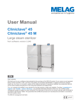
2.1 Chamber overview
Figure 5: CO
2
incubator CB-S / CB-S-UL (example CB-S 170), closed
(1) Triangle instrument panel with RD4 controller for temperature and CO
2
(2) Door handle
(3) Main power switch
(2)
(3)
(1)
Page is loading ...
Page is loading ...
Page is loading ...
Page is loading ...
Page is loading ...
Page is loading ...
Page is loading ...
Page is loading ...
Page is loading ...
Page is loading ...
Page is loading ...
Page is loading ...
Page is loading ...
Page is loading ...
Page is loading ...
Page is loading ...
Page is loading ...
Page is loading ...
Page is loading ...
Page is loading ...
Page is loading ...
Page is loading ...
Page is loading ...
Page is loading ...
Page is loading ...
Page is loading ...
Page is loading ...
Page is loading ...
Page is loading ...
Page is loading ...
Page is loading ...
Page is loading ...
Page is loading ...
Page is loading ...
Page is loading ...
Page is loading ...
Page is loading ...
Page is loading ...
Page is loading ...
Page is loading ...
Page is loading ...
Page is loading ...
Page is loading ...
Page is loading ...
Page is loading ...
Page is loading ...
Page is loading ...
Page is loading ...
Page is loading ...
Page is loading ...
Page is loading ...
Page is loading ...
Page is loading ...
Page is loading ...
Page is loading ...
Page is loading ...
Page is loading ...
Page is loading ...
Page is loading ...
Page is loading ...
Page is loading ...
Page is loading ...
Page is loading ...
Page is loading ...
Page is loading ...
Page is loading ...
Page is loading ...
Page is loading ...
Page is loading ...
Page is loading ...
Page is loading ...
Page is loading ...
Page is loading ...
Page is loading ...
Page is loading ...
Page is loading ...
Page is loading ...
Page is loading ...
Page is loading ...
Page is loading ...
Page is loading ...
Page is loading ...
Page is loading ...
Page is loading ...
Page is loading ...
Page is loading ...
Page is loading ...
Page is loading ...
Page is loading ...
Page is loading ...
Page is loading ...
Page is loading ...
Page is loading ...
Page is loading ...
Page is loading ...
Page is loading ...
Page is loading ...
Page is loading ...
Page is loading ...
/