WPLED26DC INSTALLATION INSTRUCTIONS
IMPORTANT
READ CAREFULLY BEFORE INSTALLING FIXTURE. RETAIN THESE INSTRUCTIONS FOR FUTURE REFERENCE.
RAB xtures must be wired in accordance with the National Electrical Code and all applicable local codes. Proper
grounding is required for safety. THIS PRODUCT MUST BE INSTALLED IN ACCORDANCE WITH THE APPLICABLE
INSTALLATION CODE BY A PERSON FAMILIAR WITH THE CONSTRUCTION AND OPERATION OF THE PRODUCT.
WARNING: Make certain power is OFF before installing or maintaining xture. No user serviceable parts inside.
Thank you for buying
RAB LED lighting.
Comments? Call us at
888-RAB-1000, or email:
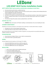
JuNcTION bOx MOuNT fOR
cONduIT
For use on applications where conduit wiring is needed.
1. Loosen and remove (4) Lens Screws. Remove Door.
2. Loosen and remove (2) Housing Screws. Remove
Housing from Back Box. Keep Housing Gasket intact
for re-assembly.
3. Secure Back Box to the mounting surface using
hardware appropriate for that mounting surface.
4. Wire the xture using UL listed wire connectors
according to NEC and local codes. Apply sealant to all
unused conduit entry points.
5. Place Gasket between Back Box and Housing.
Re-mount Housing to Back Box. Check Housing
Gasket seal all around the Back Box.
6. Re-mount Door to Housing. Tighten (4) Lens Screws.
Check door gasket (not shown) seal.
7. Fixture can be mounted in a downlight or uplight
position. Fixture may not melt heavy snow accumulation
in an uplight position.
CAUTION: For proper weatherproof function all
gaskets must be seated properly and all screws
inserted and tightened rmly.
Lens
Screws
Junction Box
Surface Mount
Back Box
Housing
Gasket
Housing
Door
Housing
Screws
suRfAce MOuNT fOR Recessed
JuNcTION bOx
For use with recessed junction box and wiring.
1. Mount Surface Plate to xture with (4) Surface Plate
Screws. There are two screws from the front and two
screws from the back. Make sure Housing Gasket
makes complete seal all the way around.
2. Use supplied crossbar. Mount Crossbar to recessed
junction box with (2) screws.
3. Place Junction Box Gasket on back of the xture.
Gasket should create seal against mounting surface.
4. Wire xture to supply wires in recessed junction box
according to wiring section.
5. Use 1/4 x 20 stainless steel Mounting Screw to attach
xture to Crossbar. Tighten Mounting Screw.
6. Cover screw with Cap, provided.
7. Fixture can be mounted in a downlight or uplight
position. Fixture may not melt heavy snow accumulation
in an uplight position.
CAUTION: For proper weatherproof function all
gaskets must be seated properly and all screws
inserted and tightened rmly.
Crossbar
Junction
Box Gasket
Mounting
Screw
Cap
Recessed
Junction Box
(not provided)
Surface
Plate
Housing
Gasket
(4) Surface
Plate Screws
fIxTuRe MOuNTINg
To ensure weatherproof seal, apply weatherproof silicone sealant around the edge of the Housing and/or Back Box. This
is especially important with an uneven wall surface. Silicone all plugs and unused conduit entries.