Page is loading ...

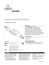
HWAT System
Installation and Operation Manual for
Hot Water Temperature Maintenance
Systems for Thermally Insulated Pipes

ii | nVent.com
Important Safeguards and Warnings
WARNING: FIRE AND SHOCK HAZARD
nVent RAYCHEM HWAT systems must be installed
correctly to ensure proper operation and to prevent
shock and fire. Read these important warnings and
carefully follow all the installation instructions.
• To minimize the danger of fire from sustained
electrical arcing if the heating cable is damaged
or improperly installed, and to comply with nVent
requirements, agency certifications, and national
electrical codes, ground-fault equipment protection must
be used on each heating cable branch circuit. Arcing may
not be stopped by conventional circuit breakers.
• Approvals and performance are based on the use of
nVent parts only. Do not substitute parts or use vinyl
electrical tape.
• Bus wires will short if they contact each other. Keep bus
wires separated.
• Connection kits and heating cable ends must be kept dry
before and during installation.
• The black heating cable core is conductive and can short.
They must be properly insulated and kept dry.
• Damaged bus wires can overheat or short. Do not
break bus wire strands when preparing the cable for
connection.
• Damaged heating cable can cause electrical arcing or
fire. Do not use metal attachments such as pipe straps or
tie wire. Use only nVent approved tapes and cable ties to
secure the cable to the pipe.
• Do not attempt to repair or energize damaged cable.
Remove damaged cable at once and replace with a new
length using the nVent RAYCHEM RayClic-S splice kit.
Replace damaged connection kits.
• Use only fire-resistant insulation which is
compatible with the application and the maximum
exposure temperature of the system to be traced.
WARNING: Water temperature above
130°F (55°C) presents a significant risk of
personal injury and/or death and requires
that scald protection measures be
implemented for safe use.

nVent.com | iii
Table of Contents
1
General Information 1
1.1 Use of the Manual 1
1.2 Safety Guidelines 2
1.3 Typical HWAT System 2
1.4 Electrical Codes 3
1.5 Approvals 3
1.6 Warranty 4
1.7 Trade Coordination 4
1.8 General Installation Notes 5
1.9 Tools Required 6
2
Heating Cable Verification and Selection 7
2.1 Heating Cable 7
3
Heating Cable Installation 8
3.1 Heating Cable Storage 8
3.2 Pre-Installation Checks 8
3.3 Installation 8
4
Heating Cable Components 14
4.1 General Connection Kit Information 14
5
Control and Monitoring 16
5.1 HWAT-ECO-GF and ACS-30 Controllers 16
6
Thermal Insulation 17
6.1 Insulating the System 17
6.2 Insulation Installation 17
7
Power Supply and Electrical Protection 20
7.1 Voltage Rating 20
7.2 Circuit Breaker Sizing 20
7.3 Electrical Loading 20
7.4 Ground-Fault Protection 21
8
Commissioning and Preventive Maintenance 22
8.1 Tests 22
8.2 Preventative Maintenance 24

iv | nVent.com
9
Test Procedures 25
9.1 System Tests 25
9.2 Fault Location Tests 31
9.3 Cable and Connection Continuity
10
Test Procedures 34
11
Troubleshooting Guide 38

nVent.com | 1
1.1 Use of the Manual
This installation and operation manual is for
nVent RAYCHEM HWAT Hot Water Temperature
Maintenance systems installed on thermally
insulated pipes only.
This manual details how to install and operate
an HWAT system. The HWAT system includes
the nVent RAYCHEM HWAT-R2 heating
cable, RayClic connection kits, and the nVent
RAYCHEM HWAT-ECO-GF or ACS-30 controllers.
It is important to review this manual and
the following documents with the installing
contractor:
• HWAT System Catalog (H57538)
• HWAT System Design Guide (H57510)
• HWAT-ECO-GF Data Sheet (H60160)
• ACS-30 Mulitpoint Commercial heat-tracing
Control System Data Sheet (H58261)
• HWAT Heating Cable Data Sheet (H57512)
• RayClic Connection System Data Sheet
(H57545)
• HWAT-ECO-GF Installation and Operation
Manual (H60223)
• ACS-30 Programming Guide (H58692)
For additional information, contact:
nVent
7433 Harwin Drive
Houston, TX 77036
USA
Tel: +1.800.545.6258
Fax: +1.800.527.5703
nVentthermal.com
Important: For the nVent warranty and agency
approvals to apply, the instructions that are
included in this manual and product packages
must be followed.
General Information
1

2 | nVent.com
General Information
1
1.2 Safety Guidelines
The safety and reliability of any heat-tracing
system depends on the quality of the products
selected, and on proper design, installation,
and maintenance. Incorrect design, handling,
installation, or maintenance of any of the
system components can cause underheating
or overheating of the pipe, or damage to the
heating cable system, and may result in system
failure, electric shock, or fire. The guidelines
and instructions contained in this guide are
important. Follow them carefully to minimize
these risks and to ensure that the HWAT system
performs reliably.
Pay special attention to the following:
• Instructions marked Important
• Warnings marked WARNING
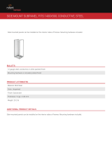
1.3 Typical HWAT System
A typical HWAT system is shown is Figure 1. The
heating cable is cut to length in the field
and is attached to the pipe with glass tape.
A power connection kit connects the heating
cable bus wires to power in a junction box.
RayClic tees and splices accommodate pipe
branches to connect two or three heating cables
together. An end seal kit is used to terminate
the end of the heating cable. A controller is used
to set the maintain temperature and improve
energy savings.

nVent.com | 3
General Information
1
Splice
To power
distribution
panel
Note: Partial pipe insulation
shown here for clarity.
All pipes must be fully
insulated
End
seal
Tee
Thermal
insulation
Heating
cable
Pipe
temperature
sensor
Temperature
sensor
Heating
cable
Insulation
Glass
tape
Power
connection
Controller
To BMS
ETL
label
180°
Figure 1: Typical HWAT heating cable system
1.4 Electrical Codes
Section 427 of the National Electrical Code
(NEC), and Part 1, Section 62 of the Canadian
Electrical Code (CEC), in particular, govern the
installation of electrical heat-tracing systems
used on hot water pipes. All installations
must be in compliance with this and any other
applicable national or local codes.
1.5 Approvals
HWAT-R2 heating cable and RayClic connection
kits are UL Listed, CSA certified and FM
Approved for use in non-hazardous locations.
The HWAT-ECO-GF controller is c-UL-us Listed
and the ACS-30 controller is c-CSA-us certified
(ACS-UIT) to US and Canadian standards for us
in non-hazardous locations. Refer to the specific
product data sheets for details.

4 | nVent.com
General Information
1
1.6 Warranty
nVent standard limited warranty applies to all
products.
An extension of the limited warranty period
to ten (10) years from the date of installation
is available if a properly completed on-line
warranty form is completed within (30) days
from the date of installation. The extension is
valid for the HWAT-R2 heating cable, RayClic
connection kits and accessories, but not the
HWAT-ECO-GF or ACS-30 controllers.
You can access the complete warranty on
nVentthermal.com/support/warranty.
1.7 Trade Coordination
Installation of an HWAT system can involve or
impact the work of numerous trades. Therefore,
effective and early coordination between
trades is a critical aspect of all HWAT system
installations. The installation of the heating
cable and connections must be properly
scheduled, along with the scheduling of the
risers and insulation installation.
This guide will assist the installer throughout the
installation process and must be reviewed by all
affected trades before installation of the HWAT
system begins. In a fast-track job, the HWAT
system must be considered a critical path item:
the pipe, heating cable, insulation, and wallboard
must all be installed in the proper order, since
the heating cable cannot be installed later.
If, for example, the walls go up before the
heating cable commissioning tests have been
completed, it may be necessary to remove the
walls in order to repair a damaged or improperly
installed system.
Ensuring that the installation of the HWAT
system is included in the overall construction
schedule will help ensure a successful and
trouble-free installation.

nVent.com | 5
1.8 General Installation Notes
Read and observe the instructions in this guide
to insure that the HWAT system is installed
successfully.
• Accidental damage to the system can be
minimized during construction by installing
thermal insulation on the pipe immediately
after the pipe has been traced and the heating
cable has been tested.
• Read all installation documentation to
familiarize yourself with the system
components.
• Read and follow all warnings and
recommendations. All involved trades should
review this entire guide and assess the
recommendations applicable to their scope
of work.
• All heat-traced pipes and equipment must be
thermally insulated. Insulation is an essential
part of the HWAT system. For an effective
system, the fiberglass insulation must be a
specific thickness for each specific pipe size
as detailed in Table 2 on page17.
• Do not install the HWAT system below the
minimum installation temperature.
–The minimum installation temperature for
HWAT heating cables is 0°F (–18°C)
–The minimum installation temperature for
HWAT-ECO-GF is 40°F (5°C).
• Ensure that your water heater temperature is
set at your desired pipe maintain temperature.
• Do not energize cable when it is coiled or on
the reel.
• Never use metal tie wire or pipe straps to
secure heating cables to pipes.
Important: Exceeding 185°F (85°C) for
HWAT-R2 will decrease the power output of the
heating cables over time.
General Information
1

6 | nVent.com
1.9 Tools Required
For installing cable and connection kits:
• Utility knife
• Diagonal cutters
• Cable cutters
• Tape measure
• Screwdriver
• Heat gun or propane torch
For testing the heating cable:
• Megohmmeter 2500 Vdc
• Multimeter (voltage, resistance and
capacitance)
General Information
1

nVent.com | 7
Heating Cable Verification
and Selection
2
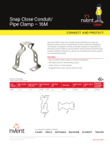
2.1 Heating Cable
The HWAT system includes HWAT-R2 heating
cable designed to maintain the piping at
specific temperature settings with the use of
the HWAT-ECO-GF or ACS-30 controllers. Figure
2 shows the construction of the heating cable.
Nickel-plated copper bus wires
Self-regulating conductive core
Polymer-coated aluminum wrap
Tinned-copper braid
Modified polyolefin
outer jacket
Modified polyolefin inner jacket
Figure 2: HWAT-R2 heating cable
The minimum control setpoint for HWAT-R2 is
105°F (40°C). The maximum control setpoint for
HWAT-R2 is 140°F (60°C).

8 | nVent.com
Heating Cable Installation
3
3.1 Heating Cable Storage
• Store the heating cable in a clean, dry location.
Temperature range: 0°F (–18°C) to
140°F (60°C).
• Protect the heating cable from
mechanical damage.
3.2 Pre-Installation Checks
Check materials received:
• Review the heating cable design and compare
the list of materials to the catalog numbers
of the heating cables and connection kits
received to confirm that the proper materials
are on site. The heating cable type is printed
on its jacket.
• The HWAT system is limited to 208–277 V
service when using the HWAT-ECO-GF
controller. When using the ACS-30 controller
the voltage range is also 208–277 V. Ensure
that the service voltage available is correct.
• Inspect the heating cable and connection kits
to ensure there is no in-transit damage.
• Verify that the heating cable jackets are
not damaged by conducting the insulation
resistance test (refer to Section 9) on each reel
of cable. Do not power the heating cable when
it’s on the reel.
Check piping to be traced:
• Make sure all mechanical pipe testing
(i.e. hydrostatic testing/purging) is complete
and the system has been cleared by the client
for tracing.
• Walk the system and plan the routing of the
heating cable on the pipe.
• Inspect the piping and remove any burrs, rough
surfaces or sharp edges.
3.3 Installation
• Pay out the heating cable, loosely stringing it
along the pipe, making sure that the
cable is always next to the pipe when
crossing obstacles.

nVent.com | 9
• Install HWAT heating cable in straight runs
along the pipe. Spiraling the heating cable is
not necessary.
• If the cable is on the wrong side of an obstacle
such as a crossing pipe or I-beam, you will
need to reinstall it or cut and splice it.
• When installing the heating cable, the cable
must not be compressed or pinched between
two objects. Wall and floor penetrations and
pipe hangers are particular areas of concern.
Figure 3: Protecting the heating cable in floor
penetrations
• Run insulation through the pipe hanger
ensuring that t
he pipe is not resting
on the heater.
Figure 4: Pipe hanger with heating cable
• When making floor or wall penetrations, make
sure the hole is large enough to accommodate
the pipe and the thermal insulation. When
sealing around pipes at floor penetrations,
avoid damaging or cutting the heating cable, or
pinching it between the pipe and the concrete.
Heating Cable Installation
3

10 | nVent.com
• The heating cable must not be embedded
directly in the sealing material; the pipe should
have thermal insulation over it (if allowed by
local codes) or the heating cable should be run
through the penetration in a tube or conduit. If
the conduit must be sealed, use a pliable fire-
resistant material (STI Firestop, Dow Corning
Fire Stop, 3M Fire Barrier, or T&B Flame-Safe)
that can be removed if necessary.
Figure 5: Multiple pipe floor penetration
• On vertical piping groups, run the heating
cable along the inside of the pipe close to
other pipes so it will not be damaged if the
pipe hits the side of the floor penetration. Run
the heating cable over the outside of the pipe
support. Do not clamp the heating cable to the
pipe with the pipe support.
• In high-rise construction it may be necessary
to install the HWAT system 10 or 12 floors at
a time to fit into the construction schedule.
If so, the end of the heating cable should be
sealed with a RayClic-E end seal and placed
in an accessible location. This allows testing
of one part of the heating cable at a time, and
allows splicing it to another section when the
system is complete.
Paying out the cable:
• Use a reel holder that pays out smoothly with
little tension. If the heating cable snags,
stop pulling.
• Keep the heating cable strung loosely but close
to the pipe being traced to avoid interference
with supports and equipment.
• Meter marks on the heating cable can be used
to determine cable length.
Heating Cable Installation
3

nVent.com | 11
• Protect all heating cable ends from moisture,
contamination and mechanical damage.
Figure 6: HWAT cable layout
When paying out the heating cable, AVOID:
• Sharp edges
• Excessive pulling force or jerking
• Kinking and crushing
• Walking on it, or running over it with equipment
WARNING: Fire and shock hazard. Do not install
damaged cable. Connection kits and cable ends
must be kept dry before and during installation.
Positioning heating cables
If possible, position the heating cable on
the lower section of the pipe, at the 4 or
8 o’clock positions, as shown below, to
protect it from damage.
Heating Cable Installation
3

12 | nVent.com
Figure 7: Cable positioning
Attaching the heating cable
Starting from the end opposite the reel, tape the
heating cable to the pipe every 2 feet. Work back
to the reel. Leave extra heating cable at the power
connection, at all sides of splices and tees to
allow for future servicing. See Table 1 on page15.
• Install heating cable connection kits
immediately after attaching the heating cable.
If immediate installation is not possible,
protect the heating cable ends from moisture.
Bending the cable
When positioning the heating cable on the pipe,
do not bend tighter than 1/2” radius. The heating
cable does not bend easily in the flat plane. Do
not force such a bend, as the heating cable will
be damaged.
1/2"
Figure 8: Bending technique
Crossing the cable
HWAT heating cables are self-regulating and
may be overlapped whenever necessary without
overheating or burning out.
Cutting the cable
Cut the heating cable to the desired length after
it is attached to the pipe. HWAT can be cut to
length without affecting the heat output per foot.
Heating Cable Installation
3

nVent.com | 13
Attachment tapes
To ensure that the heating cable is in full contact
with the pipe, use tape to attach the heating
cable to the pipe every 2 ft (.6 m). Use nVent
RAYCHEM GT-66 attachment tape. One roll will
handle approximately 50 ft (15 m) of cable.
Figure 9: Attaching the heating cable
To ensure sufficient heat transfer nVent
RAYCHEM AT-180 aluminum tape must be used
to install the heating cable on plastic pipes as
shown in Figure 10.
WARNING: Do not use metal attachments
such as pipe straps or tie wire. Do not use
vinyl-based electrical or duct tape. Use only
nVent approved tapes.
HWAT
heating cable
Continuous AT-180
alluminum tape
over heating cable
Rigid plastic pipe
Thermal
insulation
Figure 10: Installed on plastic pipe with
aluminum tape
GT-66 glass tape
2 ft.
Heating Cable Installation
3

14 | nVent.com
Heating Cable Components
4
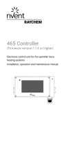
4.1 General Connection Kit Information
RayClic connection kits must be used with
HWAT-R2 heating cable. A complete circuit
requires a power connection and an end seal.
Splices and tees and other connection kits are
used as needed. Use the HWAT System Design
Guide (H57510) to select appropriate connection
kits. Installation instructions are included
with every connection kit. Steps for preparing
the heating cable and installing connection
kits must be followed. HWAT connection
kit locations should be noted on “As Built”
drawings. Connection kit locations should be
marked on the outside of the insulation cladding
with the labels provided in the kits.
RayClic-PT
powered
tee
RayClic-PC
powered connection
RayClic-S
splice
RayClic-X
cross tee
RayClic-T
tee
RayClic-PS
powered
splice
RayClic-LE
lighted end seal
RayClic-E
end seal
Alternate
lighted end seal
Alternate
connection kits
HWAT
heating cable
Figure 11: RayClic connection system
Connection Kit Installation
• When practical, mount the connection kits on
top of the pipe. All heating cable connections
must be mounted above grade level.
• Leave excess cable to serve as a service loop
at all connection kits (power, splice, cross or
tee) for future maintenance, as detailed in
Table 1. The additional heating cable will easily
pay for itself in time savings if it becomes
necessary to check or replace a connection kit
after installation. Splices and tees should have
a service loop on each of the heating cables
entering the connection kit.

nVent.com | 15
Heating Cable Components
4
TABLE 1: SERVICE LOOPS FOR EACH CONNECTION KIT
Connection # of cable Cable length/ Total cable length
kit name connections/kit connection (Service loop)
RayClic-PC 1 2.0 ft (0.6 m) 2 ft (0.6 m)
RayClic-S 2 1.0 ft (0.3 m) 2 ft (0.6 m)
RayClic-T 3 1.0 ft (0.3 m) 3 ft (0.9 m)
RayClic-X 4 1.0 ft (0.3 m) 4 ft (1.2 m)
RayClic-PS 2 1.5 ft (0.5 m) 3 ft (0.9 m)
RayClic-PT 3 1.3 ft (0.4 m) 4 ft (1.2 m)
RayClic-E 1 NA NA
RayClic-LE 1 2.0 ft (0.6 m) 2.0 ft (0.6m)
• All power connection kits must be installed in
accessible locations. Access to splices, tee
kits and end seals is recommended for future
modification or maintenance but is not required.
• Locate junction boxes for easy access but not
where they may be exposed to mechanical abuse.
• Heating cables must be installed over, not
under, pipe straps used to secure components.
WARNING: The black heating cable core is
electrically conductive and can short. It must be
properly insulated and kept dry. Damaged bus
wires can overheat or short.
WARNING: Fire and shock hazard.
nVent RAYCHEM brand specified components
must be used. Do not substitute parts or use
vinyl electrical tape.
WARNING: Water temperature above
130°F (55°C) presents a significant risk of
personal injury and/or death and requires
that scald protection measures be
implemented for safe use.

16 | nVent.com
5.1 HWAT-ECO-GF and ACS-30 Controllers
The HWAT-ECO-GF controller is designed for use
only with HWAT-R2 heating cable and must be
used to ensure proper water temperature.
Refer to the HWAT-ECO-GF Installation and
Operation Manual (H60223) for the installation
and operation instructions of the controller.
Figure 12: HWAT-ECO-GF controller
The ACS-30 Control System is also approved
for use with HWAT-R2 heating cable. Refer to
the ACS-30 Programming Guide (H58692) for
the installation and operating instructions of the
control system.
Heat-tracing system
ACS-UIT2
(Optional)
RMM2
COMMON
ALARM
POWER CONTROL
MODULE
ACCS-PCM-5
COMMON
ALARM
POWER CONTROL
MODULE
ACCS-PCM-5
ACS-PCM2-5 ACS-PCM2-5
Figure 13: ACS-30 Control System
Control and Monitoring
5
/