Page is loading ...

nVent.com
Download Full EN Manual
HWAT-ECO
INSTALLATION AND OPERATION MANUAL FOR
HOT WATER TEMPERATURE MAINTENANCE
SYSTEM ELECTRONIC CONTROLLER

ii | nVent.com
Important Safeguards and Warnings
WARNING: FIRE AND SHOCK HAZARD
nVent RAYCHEM HWAT Systems must be installed correctly to ensure
proper operation and to prevent shock and fire. Read these important
warnings and carefully follow all the installation instructions.
• To minimize the danger of fire from sustained electrical arcing if the
heating cable is damaged or improperly installed, and to comply with
nVent Thermal Management requirements, agency certifications,
and national electrical codes, ground-fault equipment protection
must be used on each heating cable branch circuit. Arcing may not
be stopped by conventional circuit breakers.
• Approvals and performance are based on the use of nVent Thermal
Management parts only. Do not substitute parts or use vinyl
electrical tape.
• Bus wires will short if they contact each other. Keep bus wires
separated.
• Connection kits and heating cable ends must be kept dry before and
during installation.
• The black heating cable core is conductive and can short. They must
be properly insulated and kept dry.
• Damaged bus wires can overheat or short. Do not break bus wire
strands when preparing the cable for connection.
• Damaged heating cable can cause electrical arcing or fire. Do not
use metal attachments such as pipe straps or tie wire. Use only
nVent Thermal Management approved tapes and cable ties to secure
the cable to the pipe.
• Do not attempt to repair or energize damaged cable. Remove
damaged cable at once and replace with a new length using the
nVent RAYCHEM RayClic-S splice kit. Replace damaged connection
kits.
• Use only fire-resistant insulation which is
compatible with the application and the maximum exposure
temperature of the system to be traced.

nVent.com | iii
Table of Contents
1
General Information 1
1.1 Use of the Manual 1
1.2 Features 1
1.3 Technical Data 3
1.4 Care and Maintenance 7
1.5 Heating Cables 7
2
Installation 9
2.1 Installing the Controller 9
2.2 Wiring the Controller 13
3
Programming the Controller 26
3.1 Programming Overview 26
3.2 Initializing the Controller 27
3.3 Advanced Programming 33
4
Error/Alarms and Troubleshooting 45
5
Pre-Defined Programs 50
6
Heat-Up Cycle Graphs 52
7
Cool-Down Graph 54

iv | nVent.com
A
F
B
C
D
E
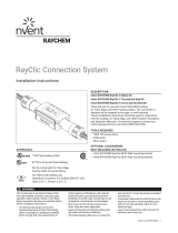
Item Qty Description
A 1 HWAT-ECO controller
B 1 Temperature sensor with 13 ft (4 m) cable
C 2 Mounting screws
D 2 Mounting washers
E 1 Aluminum tape
F 1 Manual
INSTALLATION AND OPERATION MANUAL FOR
HOT WATER TEMPERATURE MAINTENANCE
SYSTEM ELECTRONIC CONTROLLER
THERMAL MANAGEMENT SOLUTIONS
WWW.THERMAL.nVent.COM
HWAT-ECO
Figure 1: Kit contents

nVent.com | v
Power supply (green LED)
Power to heating cable (green LED)
Heat-up cycle (green LED) - increased risk of scalding
Pipe Temperature alarm (requires installed sensor) (green LED)
Alarm (red LED)
Escape, backspace; NO; or display maintain temperature setpoint
Arrow keys: to change menu selection or position the cursor
Confirm selection, new value or YES
6.5"
(165 mm)
2 ea - 1/2" conduit
entries
To water heater sensor
To HWAT-ECO network/alarm
entries
3.4"
(85 mm)
A
B
C
D
E
F
G
H
A
B
C
D
E
F
G
H
Figure 2: HWAT-ECO controller

vi | nVent.com

nVent.com | 1
General Information
1
1.1 Use of the Manual
This manual covers the installation and operation of
the nVent RAYCHEM HWAT-ECO controller and must
be used with the following additional documents:
• HWAT System Product and Selection Design Guide
(H57538)
• HWAT System Installation and Operation Manual
(H57548)
Important: For the nVent warranty and agency
approvals to apply, the instructions included in this
manual and product packages must be followed.
1.2 Features
The HWAT-ECO controller is designed for operation
with nVent RAYCHEM HWAT-Y2 and HWAT-R2 self-
regulating heating cables. The HWAT-ECO controller
provides the following features:
• Flexible temperature control of hot water
temperature maintenance systems.
• Integrated function that lowers the maintain
temperature during low use hours to save energy.
• Heat-Up cycle function that increases the water
temperature in a stagnant pipe.

2 | nVent.com
General Information
1
• Building Management System (BMS) interface
that receives a DC voltage to set the maintain
temperature.
• Alarm relay to signal power, temperature, or
communication problems.
• Pipe temperature monitoring, low temperature
alarm and high temperature cut-out.
• Master/slave function that allows one HWAT-ECO
to control up to eight additional HWAT-ECO
controllers.
• 9 pre-defined programs that can be customized by
the user.

nVent.com | 3
General Information
1
1.3 Technical Data
Use Only for HWAT-Y2 and
HWAT-R2 heating cables
Maintain temperature
setpoint
1 4) o 14
)
Hot water piping
ambient temperature
1) o )
Controller ambient
temperature
4 ) o 1 4)
ambient
Switching capacity 24 A 208/240 Vac max.
Operating voltage 208/240 (±10%), 60 Hz
Internal power
consumption
2.5 W
Circuit protection
(not provided with
HWAT-ECO controller)
Max. 30 A with 30 mA
ground-fault protection
Power terminal block 16–10 AWG (1.5–4 mm
2
)
Use copper conductors
only
Internal temperature
alarm
1 )
BMS control voltage 0–10 Vdc
BMS cable maximum
length
328 ft (100 m)

4 | nVent.com
General Information
1
Alarm contacts Max. 24 Vdc or 24 Vac,
1A, SPST, voltage free,
NO/NC
Alarm events • Loss of power
• Controller reinitialized
• Internal controller
temperature too high
• Lost date and time
settings
• Internal failure
• Pipe temperature too
high (optional)
• Pipe heater temperature
too low (optional)
• Network error
Power correction factor To increase or decrease
your actual pipe maintain
temperature or adjust for
plastic pipe.
Pipe temperature sensor Thermistor with 13 ft
4) ea poe
A PT100 RTD may be
optionally used. Max
length is 328 ft (100 m)

nVent.com | 5
General Information
1
Electromagnetic Complies to EN 5014-1
Compatibility (EMC) for
emission and 60730-1 for
immunity
Real time clock Leap year correction
Clock accuracy ±10 minutes per year
Enclosure rating NEMA 12 (IP54) – indoor
use only
Enclosure material ABS
Mounting Wall mount with two
screws or optional DIN rail
Conduit entries 2 ea – 1/2 in conduit entries
Cable gland 3-hole grommet
Maximum cable size:
• 2-wire: 20 AWG (0.5 mm
2
)
• 4-wire: 24 AWG (0.2 mm
2
)
Default programs 9 pre-defined programs
that can be customized
by user
Program settings 48 1/2-hour time blocks
of the following program
settings: Off, Economy,
Maintain and Heat-Up
cycle

6 | nVent.com
General Information
1
Password 4-digit password protection
Master/slave Master is selectable in the
controller, up to 8 slaves
can be connected
Master/slave cable 2-wire, min. 24 AWG
(0.2 mm
2
) twisted pair
and insulation of 300 V,
Max length cable is 100 m
Parameters in memory All parameters are stored
in nonvolatile memory,
except time and date
Clock backup time Rechargable Lithium
battery. Battery will retain
time and date for up to 30
days when power is lost
Approvals
80BJ
Type 12
Energy Management Equipment
(for use with HWAT-R2 and HWAT-Y2 heating cables only.)
Weight 2 lbs (1 kg)
Size 6.5 in x 3.4 in x 2.8 in
(165 mm x 85 mm x
71 mm)

nVent.com | 7
General Information
1
1.4 Care and Maintenance
To clean the HWAT-ECO use a damp cloth. Do not
use solvents. Do not pour water directly on the
device. Do not use a water hose or high pressure
cleaner.
Important: In case of questions or product failure,
please contact your nVent representative, or call nVent
at 800-545-6258.
1.5 HWAT Heating Cables
Maintain temperature
Depending on the ambient temperature and voltage,
HWAT-Y2 is designed to maintain temperatures up to
1 ) an egne o anan
epeae p o 14 )
Installing the heating cables
Install the HWAT heating cable system as instructed
in the HWAT System Installation and Operation
Manual (H57548). The controller must be installed
by a professional electrical installer familiar with
electrical safety codes and practices.

8 | nVent.com
General Information
1
Ground-fault protection
WARNING: To minimize the danger of fire from
sustained electrical arcing if the heating cable is
damaged or improperly installed, and to comply with
the requirements of approvals agencies, nVent and
national electrical codes, ground-fault equipment
protection must be used on each heating cable
branch circuit. Arcing may not be stopped by conven-
tional circuit protection. The HWAT-ECO does not
include ground-fault protection.
Pre-Installation testing
Prior to installing the HWAT-ECO controller, perform
the insulation resistance (Megger) test and circuit
length verification (Capacitance) test on the heating
cable as detailed in the HWAT System Installation
and Operation Manual (H57548).

nVent.com | 9
Installation
2
2.1 Installing the Controller
Install the controller in an indoor, dry, clean,
accessible location. If using the optional pipe
temperature sensor,
make sure you install the
controller within 328 ft (100 m)
of where you want to
monitor the pipe temperature.
Opening the controller
WARNING: To prevent shock, always switch off
the power supply (circuit breaker) before opening the
controller.
The HWAT-ECO has a removable front cover. Both
the cover and the box have electronic parts and are
connected to each other by a 14-pin connector. First
unscrew the four screws in the cover. Carefully pull
the cover straight out, not sideways!

10 | nVent.com
Installation
2
Figure 3: Opening the controller
Wall mounting the controller
Mount the controller using either of the options
below:
1. You can mount the controller to the wall using
the two supplied screws and sealing rings in the
two holes located inside the bottom part of the
controller.

nVent.com | 11
Installation
2
5.9" (148 mm)
1.7"
(43 mm)
TEMP BMS
B A
Figure 4: Hole locations for mounting with screws

12 | nVent.com
Installation
2
2. Optionally you can mount the controller using DIN
35 Rail mounting.
Optional Din Rail Mount
(Rail not provided)
Mounting
Removing
Press tab to remove box
Figure 5: Mounting with DIN 35 Rail

nVent.com | 13
Installation
2
2.2 Wiring the Controller
The diagram below shows the arrangement of the
terminal blocks for power, alarm, pipe temperature
sensor, BMS and network.
Ground
HWAT-ECO
General Arrangement
Power
terminal block
Sensor, BMS,
and network
terminal block
Alarm
terminal block
Ø
1
Ø
2
HWAT Line
Ø
1
Ø
2
TEMP BMS
B A
Figure 6: General arrangement for terminal blocks

14 | nVent.com
Installation
2
The diagram below shows the connection of a single
controller (without optional water heater sensor,
BMS, network and alarm connections).
Important: Tighten the terminal screws to 6 inch-
lbs. (0.68 N-m)
Ø
Ø
G
1/2"
Conduits
HWAT
heating
cable
RayClic-PC
Max. 30 A
ground fault
circuit breaker
208-240 Vac
Ground
Incoming power
208/240 Vac Max
Wiring diagram
for HWAT-ECO
To
HWAT
heating
cable
TEMP BMS
B A
Figure 7: Connecting a single controller
(w/o sensor, BMS, network and alarm connections)
/