Page is loading ...

Operators Manual
Metering Filling Station
Installation & Operation
For units built after August 2011
MFS
Cleveland
™
1333 East 179th St., Cleveland, Ohio, U.S.A. 44110
Ph: 216.481.4900 Fx: 216.481.3782
www.clevelandrange.com
Model # & Serial #.
(Open front panel to view rating label.)
For your future reference.
Model # ______________________________________
Serial # _______________________________________
Read the manual thoroughly.
Improper installation, operation or
maintenance can cause property
damage, injury or death.
!
SE95019 Rev. 10
July 2011
TABLE OF CONTENTS
For your safety . . . . . . . . . . . . . . . . . . . . . . . . . . . . . . . . . . . . . . . . . . . . . . 1-2
Preventative Maintenance . . . . . . . . . . . . . . . . . . . . . . . . . . . . . . . . . . . . . . . 2
Installation . . . . . . . . . . . . . . . . . . . . . . . . . . . . . . . . . . . . . . . . . . . . . . . . . . . 3
Operating Instructions . . . . . . . . . . . . . . . . . . . . . . . . . . . . . . . . . . . . . . . . .4-5
Cleaning Instructions . . . . . . . . . . . . . . . . . . . . . . . . . . . . . . . . . . . . . . . . . 6-8

WARNING: Improper
installation, adjustment,
alteration, service,
maintenance or operation
can cause property
damage, injury or death.
Read the installation and
operating instructions
thoroughly before
installing or servicing this
equipment.
This appliance is not to be used by
persons with reduced physical,
sensory or mental capabilities, or lack
of experience and knowledge, unless
they have been given supervision or
instruction concerning use of the
appliance by a person responsible for
their safety.
This appliance is not for use by
children and they must be supervised
not to play with it.
Retain this manual for your reference.
AVERTISSEMENT : Une
mauvaise installation, un
réglage inadapté, une
modification non appropriée
ou un manque d'entretien
peuvent occasionner des
dommages matériels, des
blessures ou même la mort.
Lire la notice de montage et
d'exploitation avant
d'installer ou d'entretenir cet
équipement.
Cet appareil ne doit pas être utilisé par
des personnes dont les capacités
physiques, sensorielles ou mentales sont
réduites, ou des personnes dénuées
d'expérience ou de connaissance, sauf si
elles ont pu bénéficier, par l'intermédiaire
d'une personne responsable de leur
sécurité, d'une surveillance ou
d'instructions préalables concernant
l'utilisation de l'appareil.
Cet appareil n'est pas destiné à être
utilisé par des enfants et ils doivent être
surveillés pour s'assurer qu'ils ne jouent
pas avec l'appareil.
Conservez ce manuel pour votre
référence
ADVERTENCIA: La
instalación, ajuste,
alteración, servicio,
mantenimiento o
funcionamiento incorrectos
pueden causar daños a la
propiedad, lesiones o
muerte. Lea detenidamente
las instrucciones de
instalación y de operación
antes de instalar o darle
servicio a este equipo.
Este aparato no debe ser utilizado por
personas con capacidades físicas,
sensoriales o mentales reducidas, o
que no tengan la experiencia y los
conocimientos adecuados, a menos
que estas personas hayan recibido
supervisión e instrucciones en cuanto
al uso del aparato por la persona
responsable de la seguridad de ellas.
Guarde este manual para su
referencia.
FOR YOUR SAFETY / POUR VOTRE SÉCURITÉ /
PARA SU SEGURIDAD
1.
FOR YOUR SAFETY
Do not store or use
gasoline or any other
flammable liquids and
vapours in the vicinity of
this or any other
appliance.
POUR VOTRE SÉCURITÉ
Ne pas entreposer ou
utiliser d'essence ou
d'autres liquides ou
vapeurs inflammables à
proximité de cet appareil
ou de tout autre appareil.
PARA SU SEGURIDAD
No guarde ni use gasolina
o cualesquiera otros
líquidos o vapores
inflamables en las
cercanías de éste o
cualquier otro aparato.

Keep hands away from moving parts and pinch
points. / Gardez les mains loin des pièces mobiles et
des points de pincement. / Mantenga las manos
lejos de piezas movibles y puntos de presión muy
localizada
.
Surfaces and product may be hot! Wear protective
equipment. /Les surfaces et le produit peuvent être
chauds! Portez un équipement de protection. / ¡Las
superficies y el producto pueden estar calientes!
Utilice equipo protector.
Hot! / Chauds ! / ¡Caliente!
Do not climb, sit or stand on equipment. /Il ne faut
pas monter, s'asseoir ni se tenir debout sur
l'équipement. /No subirse, ni sentarse ni pararse
sobre el equipo.
Stand clear of product discharge path when
discharging hot product. / Écartez-vous du chemin
de décharge d’un produit chaud. / Permanezca
alejado de la ruta de descarga del producto al vaciar
producto caliente.
Use wheel locks. / Utiliser des verrous de roue. /
Utilizar bloqueos de la rueda.
Do not remove guards or operate without them. / Ne
pas supprimer les gardes ou fonctionner sans eux. /
No retire los guardias ni funcionar sin ellos.
Floor may become slippery from product spillage. /
Déversement de produit peut causer de plancher à
être glissante. / Derrame de producto puede causar
piso a ser resbaladizo.
0
Inspect unit daily for proper operation. / Inspectez
l’unité tous les jours pour son bon fonctionnement. /
Inspeccione diariamente el funcionamiento correcto
de la unidad.
Remove air pressure prior to servicing or cleaning. /
Dépressurisez avant tout entretien. / Despresurizar
antes de darle servicio.
IMPORTANT / IMPORTANT / IMPORTANTE
CAUTION / ATTENTION / PRECAUCIÓN
SERVICING / ENTRETIEN / SERVICIO
Hazard warnings are for your safey. Absence of a warning does not mean
the hazard is not present. Unforeseen actions may result in unanticipated
hazards. / Les avertissements de danger sont pour votre sécurité. L’absence
d'un avertissement ne signifie pas que le danger n'est pas présent. Les
actions imprévues peuvent entraîner des dangers imprévus. / Las
advertencias sobre los peligros son para su seguridad. La ausencia de una
advertencia no significa que el peligro no está presente. Las acciones
imprevistas podrían resultar en peligros no anticipados.
FOR YOUR SAFETY / POUR VOTRE SÉCURITÉ / PARA SU SEGURIDAD
Bag clippers come in various models. Follow all safety
instructions in their specific manual. / Il existe une variété
de modèles de pinces de sacs. Suivez toutes les consignes
de sécurité figurant dans leur propre manuel. / Las
engrapadoras de bolsas vienen en varios modelos. Siga
todas las instrucciones de seguridad en su propio manual
2.
DAILY PRE-STARTUP
INSPECTION
1. Unit has been assembled properly
and all hose and pipe fittings are tight.
2. Check air pressure.
3. Test single stroke operation.
4. Test continuous operation.
WEEKLY
1. 95 to100 psi. air pressure.
2. Check air filter collector.
3. Check all fittings for leaks-oil level.
4. Lubricator should be adjusted to disperse 1 drop of oil
per 14-18 cycles. (None detergent oil)
5. The flapper valve assembly must removed and
inspectedfor signs ware and proper adjustment.
6. Check for loose fasteners, switches, pistons heads, etc.
7. Gaskets and O-ring wear.
PREVENTATIVE MAINTENANCE
FOR MAINTENANCE AND
REPAIRS CONTACT YOUR
AUTHORIZED MANITOWOC
SERVICE AGENCY AND HAVE
A QUALIFIED SERVICE
TECHNICIAN MAINTAIN YOUR EQUIPMENT
.
0
Have a qualified service technician maintain your
equipment. / Demandez à un technicien en entretien
et en réparation qualifié d’effectuer l’entretien de
votre équipement. / Haga que un técnico de servicio
calificado mantenga su equipo.

RECEIVING INSPECTION
Before unpacking visually inspect the unit for evidence of damage
during shipping.
If damage is noticed, do not unpack the unit, follow shipping
damage instructions
SHIPPING DAMAGE INSTRUCTIONS
If shipping damage to the unit is discovered or suspected, observe
the following guidelines in preparing a shipping damage claim.
1. Write down a description of the damage or the reason for
suspecting damage as soon as it is discovered. This will help
in filling out the claim forms later.
2. As soon as damage is discovered or suspected, notify the
carrier that delivered the shipment.
3. Arrange for the carrier's representative to examine the
damage.
4. Fill out all carrier claims forms and have the examining carrier
sign and date each form.
UNCRATING
Caution:
Straps under tension and will snap when cut.
Carton may contain staples and Skid contains Nails.
Use proper safety equipment and precautions.
Unit is heavy use adequate help or lifting equipment as needed.
1. Carefully cut any straps from container.
2. Lift off carton.
3. Inspect for hidden damage.
If found refer to “SHIPPING DAMAGE INSTRUCTIONS”.
4. Cut strap holding unit.
5. Remove manual. Write down the model# and serial# of the
unit onto the front of this manual.
6. Lift unit off skid.
7. Remove and replace accessories in a secure area.
8. Discard packaging material according to local and or state
requirements.
ASSEMBLY
The Metering Filling Station is a mobile unit that requires no
assembly to complete unless a clipper has been shipped with the
unit. It does however ship with a number of loose items that are
required for its use. These items should be stored in a convenient
location.
CLIPPER
If a clipper is supplied with the unit, it must be mounted. Remove it
from the box and connect it to the mounting bar using part
#FA11509 bolt (supplied). Connect one end of the short air hose
(supplied) to the clipper and the other end to the male quick
connect on the end of the MFS.
INSTALLATION REQUIREMENTS
Compressed Air
This unit requires a constant 25 c.f.m. (cubic feet per minute) at 90 to
100 p.s.i. (pounds per square inch).
The air must be filtered of oil, moisture and dirt. The dew point of
the supply air must be less than 65°F. The Metering Filling Station
is equipped with its' own air oiler system, therefore, no oil should
be added to the supply air. We recommend the compressed air
system be equipped with a drier, filter, and automatic water dump
on the air compressor receiver tank. If the distance between the
tank and the unit is less than 100 feet then a minimum line size of
3/4" is required. A distance of 100 to 300 feet requires a minimum
1" line.
Connect one end of air line (supplied) to the metering filling station
and the other end to the kettle air outlet fitting.
If you do not have a Cleveland kettle with air connection built-in
then you must attach the female quick connect (supplied) to your
air supply.
Electrical
No electrical connection is required unless the unit comes
equipped with a Thermal Assurance Package (TAP) option. This
requires a 115V. 1PH. grounded outlet.
INSTALLATION CHECKS
AIR PRESSURE
1. Connect supply air to metering filling station.
2. Open front Access Doors (17) on metering filling station.
3. Set Stroke Selection Switch on Control Panel (1) for
"CONSTANT PUMPING".
4. Hold Trigger Lever (10) and read Pressure Gauge (21) as
pump is operating. Pressure should not drop less than 90 psi
or exceed 110 psi.
5. Adjust as required.
Note: If there is no air to unit check the kettle's Air Quick
Connect is pushed upward to the "OPEN" position.
SINGLE STROKE
Note: Use 3" gaskets in all hex nut couplings on food
hose.
⇒ First, hand-tighten.
⇒ Then, snug with wrench.
1. Using 3" gasket, connect the 3" dia. Food Product Hose (15)
to metering filling station and kettle.
2. Add water to kettle and open kettle's product discharge
valve.
3. Open front Access Doors (17) of metering filling station.
4. Set Stroke Selection Switch on Control Panel (1) for "SINGLE
STROKE".
5. Place bag over Discharge Nozzle (11).
6. Pull and hold Trigger Lever (10).
7. Product piston should go all the way forward, then return and
stop.
8. Release Trigger Lever (10).
9. Repeat test two to four times, product will start to discharge
into bag.
CLIPPER
Refer to clipper operating instruction manual for safety and
operating procedures.
INSTALLATION
OPEN
!
3.

4.
OPERATING
INSTRUCTIONS
10
11
8
2
1
23
4 36 5 12
7
13
14
24
21
17
15
0
1
2
3
4
5
6
7
8
9
0
1
2
3
4
5
6
7
8
9
Cleveland
20
18
19
9
22
16
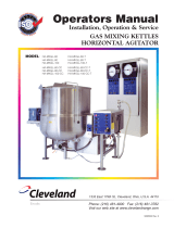
OPERATING CONTROLS
NAME FUNCTION
Discharge speed Adjusts speed of product exiting
the discharge nozzle.
Suction speed Adjusts speed of product being
pulled from kettle and into pump.
Stroke selection Selects operating mode or OFF
when not in use.
DISCHARGE
SPEED
SUCTION
SPEED
S
TROKE
SELECTION
Cleveland
F
AST SLOW FAST SLOW
S
INGLE STROKE CONSTANT PUMPING
O
FF
ITEM # DESCRIPTION FUNCTION
1. Control Panel . . . . . . . . . . . . . . . . . . . . Includes: A/ speed adjusters for suction and discharge.
B/ stroke selection switch.
2. Flapper Valve . . . . . . . . . . . . . . . . . . . . Changes direction of product flow.
3. Piston Head
4. Large Lug Nuts . . . . . . . . . . . . . . . . . . Holds product head to product cylinder.
5. Product Cylinder . . . . . . . . . . . . . . . . . Cylinder product is drawn into and discharged from.
6. Product Piston . . . . . . . . . . . . . . . . . . . Moves product within the cylinder.
7. Product Discharge Valve . . . . . . . . . . . Air cylinder that opens and closes discharge opening
by moving plunger.
8. Plunger . . . . . . . . . . . . . . . . . . . . . . . . . Opens and closes product discharge opening.
9. Discharge Valve Body
10. Trigger Lever . . . . . . . . . . . . . . . . . . . . Activates pumping action.
11. Discharge Nozzle . . . . . . . . . . . . . . . . . Directs the flow of discharge product.
12. 3" dia. Food Product Hose . . . . . . . . . . 3" dia. hose to connect Metering Filling Station hose to kettle.
13. Brake . . . . . . . . . . . . . . . . . . . . . . . . . . Locks pump in position.
14. Access Doors
15. Clipper Bracket . . . . . . . . . . . . . . . . . . Mounting bracket for optional clipper.
16. Adjustment Wheel . . . . . . . . . . . . . . . . Used for setting desired pumping volume.
17. Locking Wheel
18. Pressure Regulator Dial . . . . . . . . . . . . Used to regulate air pressure.
19. Pressure Gauge . . . . . . . . . . . . . . . . . . Shows operating pressure.
20. Slide Valve . . . . . . . . . . . . . . . . . . . . . . Safety Valve. Slide down to vent air from system.
21. Drain Pan
22. Drain Pan Discharge
23. Supply Air Connection
24. Supply Air Connection - Clipper

5.
OPERATION
1. Preform DAILY PRE-STARTUP
INSPECTION.
2. Connect on end of the 3-inch
diameter food hose to the kettle.
3. Position MFS for ease of operation and connect to
the other end of the food hose. Additional hoses or
a 90° elbow may be used.
4. Lock wheels.
5. Connect air hose from source to MFS.
6. Open VALVE on kettle. Food will flow into food
hose.
7. Place casing over discharge nozzle.
8. Pull and hold trigger lever until pump has stopped.
If a second or third stroke is required, repeat
process or set STROKE SELECTION on
CONSTANT PUMPING and hold trigger lever while
food is being pumped.
9. Move bag over to clipper and clip bag. (refer to
Tipper Tie operations manual)
10. Pump a couple of bags to check volume and
speed.
11. SUCTION SPEED is the rate at which product is
suctioned from kettle. Thick products should be
suctioned at a slow speed. Thin products may be
suctioned fast.
12. DISCHARGE SPEED is the rate at which product
flows out of the discharge nozzle. Most products
may discharge fast into bags. Discharge slowly
into pans to reduce splashing hot food.
13. Continue to pump until all product has been
emptied from the kettle.
FLUSHING & SANITIZING
BETWEEN RECIPES
1. To clean between batches of product, flush kettle
and Metering Filling Station with a warm water
and mild detergent or sanitizing solution from
kettle to loosen and remove food particles.
2. Remove product Discharge Nozzle and replace it
with cleaning hose.
3. Place end of cleaning hose over a drain.
4. Switch stroke selector switch to "CONSTANT
PUMPING".
5. Pull and hold trigger lever against discharge valve
nozzle until kettle has been emptied.
6. Add clean water to kettle, and repeat process to
rinse units.
SETTING VOLUME
METHOD “A”
1. Open front doors of MFS.
2. Release air pressure by pulling
down on SLIDE VALVE.
3. Loosen locking wheel.
4. Turn adjustment wheel as required.
5. Tighten locking wheel.
6. Pull slide valve to pressure system.
METHOD “B”
1. Set pump to single stroke.
2. Close SUCTION SPEED VALVE.
3. Trigger pump. It should move about 1/2 cycle and
stop.
4. Close DISCHARGE SPEED VALVE.
5. Release air pressure by pulling
down on SLIDE VALVE.
6. Loosen locking wheel.
7. Turn adjustment wheel as required.
8. Tighten locking wheel.
9. Open SUCTION SPEED VALVE.
10. Open DISCHARGE SPEED VALVE.
11. Pull slide valve to pressure system.
Adjusting
Wheels
A
Locked
Position
A Volume
1 1/2" = 1 gallon
3 1/2" = 3 quarts
5 1/2" = 2 quarts
NOTE:
Fine tune the distance during
start up training.
Make a template for ease of adjustment.
Approximate

DISASSEMBLY
Note: Remove "O" rings using a wooden or
plastic picker; do NOT use a sharp object.
Note: Prepare a properly diluted solution of
authorized cleaning solution in a plastic
soak bucket taken from a freshly filled sink to receive
small parts, gaskets, and "O" rings.
1. Move slide valve on kettle's air
quick connect to down position to
vent air from metering filling station.
2. Disconnect main air line from Metering Filling
Station.
3. Remove 3" food hoses.
4. Remove two air lines (quick-disconnect fittings)
from Rotary Acuator.
5. Undo 2" Sani-Clamp, and remove Discharge
Nozzle.
6. Undo Sani Clamp on Discharge Valve Body and
remove Discharge Head Assembly; place 2" gasket
in warm water to soak.
7. Disassemble Discharge Head
Assembly, follow in order;
⇒ Remove 2" Sani-Clamp that
holds Discharge Head Assembly
together.
⇒ Separate parts by pulling them
apart.
Discharge Head Assembly=
⇒ Using a wooden or plastic picker, remove
"O" Rings from plunger.
⇒ Put "O" Rings in warm water to soak; do NOT
submerge discharge valve.
8. With 2" wrench, remove Short 2" dia. Pipe, 2" dia.
Elbow and Long 2" dia. Pipe. Place all gaskets in
soak bucket.
9. Remove two air lines from Rotary Actuator on
Piston Head Assembly.
10. Using lug wrench, unscrew three Large Lug Nuts,
and remove Piston Head Assembly.
11. Dismantle Piston Head Assembly as follows in
order;
Discharge
Valve
Plunger
Discharge
Valve
Body
2" Sani
Clamps
"O" Rings
Push yellow tab down to
release air pressure before
disconnecting air hose
CLEANING INSTRUCTIONS
Product Cylinder
Piston Head Assembly
3" dia.
Food
Hose
D
ischarge Valve
Plunger
Discharge Valve Body
Discharge
H
ead
A
ssembly
S
hort
2" dia.
Pipe
P
ush
P
in
Piston Cylinder
2
" dia. Elbow
L
ong
2
" dia.
Pipe
Product
Discharge
N
ozzle
2
" Sani
Clamp
Bracket
2
" Sani
C
lamp
2" Sani
Clamp
Product Piston
Product Piston "O" Ring
G
asket
G
asket
G
asket
Gasket
Flapper Valve
"O" Ring
Spring
Large Lug Nut
Flapper
Rotary Actuator
Cylinder Seal
Shaft
Piston Head
Air Line
Air Line
0
0
6.

7.
⇒ Push Rotary Actuator toward Piston Head to remove
Flapper, place Flapper in soak bucket.
⇒ Remove Rotary Actuator, placing small spring in
soak bucket.
⇒ Do NOT submerge Rotary Actuator.
11. Pull product cylinder off product piston.
⇒ Do NOT use pliers or any other tool that could
damage the inside wall of the cylinder.
12. Using plastic or woden picker, remove "O" ring from
Product Piston.
CLEANING
WARNING: Do not submerge Discharge Valve or
Rotary Actuator in water, damage to air cylinders will
result.
⇒ Always turn off equipment power before using
water.
⇒ Never use steel wool for cleaning; particles may
become embedded and rust.
⇒ Clean unit in the following order:
A/ Warm water and mild detergent solution.
B/ Clear rinse.
C/ Properly diluted sanitizing solution (see
Sanitizing Solution Chart) to sanitize after cleaning.
⇒ Do NOT use chloride cleaners; they may
damage stainless steel surface.
⇒ For difficult cleaning applications, one of the
following can be used: alcohol, baking soda,
vinegar, or a solution of ammonia in water.
1. Clean all parts (except Discharge Valve and Rotary
Actuator) with hot soapy water or run them through
the dish washer.
2. Clean the interior of the 2" inch pipes and the 3"
dia. food product hose using the brushes provided.
3. Inspect "O" rings and gaskets for cuts, distortion, or
wear, replace if required.
4. Leave part disassembled overnight.
ASSEMBLY
NOTE: To eliminate any chance of recontamination of
unit, wear sanitary disposable gloves during reassembly
after cleaning.
This startup procedure assumes the unit is fully
disassembled.
1. Attach Product Cylinder to Piston Cylinder as
follows:
⇒ Inspect Product Piston "O" Ring (replace if worn)
on Product Piston - lubricate with food grade grease.
⇒ Push Product Cylinder over Product Piston and
seat firmly in groove (push pin must be located as
illustrated).
2. Assemble Piston Head Assembly as follows in
order:
⇒ Inspect Flapper Valve "O" ring on rotary actuator
(replace if worn).
⇒ Lubricate "O" ring with food grade grease and put
on shaft.
⇒ Put Spring on Shaft.
⇒ Slide Rotary Actuator Shaft thru hole in Piston
Head.
⇒ Mount Flapper to Shaft.
Flapper Valve
"O" Ring
Spring
Flapper
Rotary Actuator
Shaft
Piston Head
Product Cylinder
Push
Pin
Piston Cylinder
Product Piston
Product Piston "O" Ring
Flapper Valve
"O" Ring
Spring
F
lapper
Rotary Actuator
Shaft
Piston Head

8.
3. Assemble piston and piping as follows in order:
NOTE: Use 2" gaskets in all hex nut couplings.
⇒ Put Cylinder Seal in place. Lubricate exposed
portion of Cylinder Seal then mount Piston Head to
Product Cylinder, and fasten in place with large
Lug Nuts using lug wrench for final tightening.
⇒ Attach two 1/4" air lines to Rotary Actuator (black
line on top).
⇒ Reassemble 2" piping (Long 2" dia. Pipe, 2" dia.
Elbow and Short 2" dia. Pipe) on Piston Head as
illustrated using gaskets shown.
4. Assemble discharge head assembly in order as
follows:
⇒ Inspect and install "O" Rings (replace if worn) on
Plunger - larger one in top groove - smaller one in
bottom groove.
⇒ Push Plunger into Discharge Valve Body.
⇒ Attach Discharge Valve to Discharge Valve
Body using 2" Sani-Clamp.
⇒ Attach Discharge Nozzle to Discharge Valve
Body using 2" Sani-Clamp.
5. Attach Discharge Head Assembly as follows:
⇒ Mount Discharge Head Assembly on Short 2"
diameter Pipe (use Gasket).
⇒ Rotate Discharge Head Assembly into 2" Sani-
Clamp Bracket and fasten clamp.
⇒ Attach two 1/4" air lines to Discharge Valve
(black on top).
6. Pan Filler System Option:
⇒ Using Short Pipe and 45° Elbow attach as
shown
CLEANING PUMP BODY
1. Disconnect main air line from Metering Filling
Station.
2. Move pump so that Drain Pan Discharge Outlet is
over floor drain. Floor around unit may become
slippery from cleaning.
3. Remove Drain Screen. Thoroughly was and rinse
the screen in a sink or a dishwasher.
4. Prepare a warm water and mild detergent solution.
5. Remove food soil using a nylon brush.
6. Rinse thoroughly.
Discharge
Valve
Plunger
Discharge
Valve
Body
2" Sani
Clamps
"O" Rings
45°
Elbow
Short
Pipe
Discharge Head
Assembly
2" Sani
C
lamp
Bracket
2
" Piping Assembly
Gasket
Product Cylinder
Piston Head
Short
2" dia.
Pipe
2
" dia. Elbow
Long
2" dia.
P
ipe
Cylinder
S
eal
Lug Nut
Gasket
G
asket
Gasket
/