
Betrie
bsan‐
leitung
Sichere Motor-Feedback-Systeme
B E T R I E B S A N L E I T U N G
d e
Sichere Motor-Feedback-Systeme
1 Zu diesem Dokument
Bitte lesen Sie diese Betriebsanleitung sorgfältig, bevor Sie mit dem sicheren
Motor-Feedback-System arbeiten, es montieren, in Betrieb nehmen oder warten.
Nur bei konsequenter Einhaltung der Vorgaben dieser Betriebsanleitung kann der
Hersteller die Sicherheitsfunktion gewährleisten.
Dieses Dokument ist ein Originaldokument.
1.1 Funktion dieses Dokuments
Diese Betriebsanleitung leitet das qualifizierte technische Personal des Maschi‐
nenherstellers bzw. Maschinenbetreibers zur sicheren Montage, Elektroinstalla‐
tion, Inbetriebnahme sowie zum Betrieb, zur Wartung und zur Außerbetriebset‐
zung des sicheren Motor-Feedback-Systems an.
Diese Betriebsanleitung ist allen Personen zugänglich zu machen, die mit dem
sicheren Motor-Feedback-System EDS35-2/EDM35-2 arbeiten.
Darüber hinaus sind für die Planung und den Einsatz von sicherheitsgerichteten
Sensoren wie dem sicheren Motor-Feedback-System EDS35-2/EDM35-2 techni‐
sche Fachkenntnisse notwendig, die nicht in diesem Dokument vermittelt werden.
Grundsätzlich sind die behördlichen, gesetzlichen und sicherheitsrelevanten Vor‐
schriften bei der Montage und beim Betrieb des sicheren Motor-Feedback-Sys‐
tems EDS35-2/EDM35-2 einzuhalten.
1.2 Symbole und Dokumentkonventionen
WARNUNG
Ein Sicherheitshinweis weist Sie auf konkrete Vorgaben zur sicheren Montage
und Installation des sicheren Motor-Feedback-Systems EDS35-2/EDM35-2
hin. Dies soll Sie vor Unfällen bewahren. Lesen und befolgen Sie Sicherheits‐
hinweise sorgfältig!
HINWEIS
Weist auf nützliche Tipps und Empfehlungen hin.
bHandlungsanweisungen sind durch einen Pfeil gekennzeichnet. Lesen und befol‐
gen Sie Handlungsanweisungen sorgfältig.
1.3 Zugehörige Dokumente
•
Für EDS35-0V/EDM35-0V: Technische Information „HIPERFACE DSL
®
MAS‐
TER Integration Manual“, Artikelnummer 8017595, Stand vom 24.03.2020
(oder neuer).
•
Für EDS35-2V/EDM35-2V: Technische Information „HIPERFACE DSL
®
MAS‐
TER Safety Integration Manual“ Artikelnummer 8017596, Stand vom
17.01.2019 (oder neuer).
•
Auch auf eine gefährliche Fehlfunktion wird in der technischen Information
„HIPERFACE DSL
®
MASTER“ eingegangen.
2 Zu Ihrer Sicherheit
Dieses Kapitel dient Ihrer Sicherheit und der Sicherheit der Anlagenbenutzer.
2.1 Grundlegende Sicherheitshinweise
Für Einbau und Verwendung des Motor-Feedback-Systems sowie für die Inbetrieb‐
nahme und wiederkehrende technische Überprüfungen gelten die nationalen und
internationalen Rechtsvorschriften, insbesondere:
•
Maschinenrichtlinie 2006/42/EG
•
Arbeitsmittelbenutzungsrichtlinie 2009/104/EG
•
Unfallverhütungsvorschriften und Sicherheitsregeln
•
sonstige relevante Sicherheitsvorschriften
Hersteller und Bediener der Maschine, an der das sichere Motor-Feedback-Sys‐
tem EDS35-2/EDM35-2verwendet wird, müssen alle geltenden Sicherheitsvor‐
schriften und -regeln in eigener Verantwortung mit der für sie zuständigen
Behörde abstimmen und einhalten.
Der Hersteller des verbundenen Antriebssystems muss bei der Auslegung des
Antriebssystems die Sicherheitsanforderungen erfüllen, die in der technischen
Information „HIPERFACE DSL
®
MASTER“ beschrieben sind.
2.2 Bestimmungsgemäße Verwendung
Das Motor-Feedback-System ist aufgrund seiner Ausstattung zum dynamischen
und präzisen Betrieb von Servo-Regelkreisen prädestiniert.
Das Gesamtsystem, bestehend aus Encoder, Auswertesystem, Servo-Umrichter
und Motor, bildet einen Regelkreis.
Der sicherheitsgerichtete Einsatz von sicheren Motor-Feedback-Systemen
EDS35-2/EDM35-2 mit HIPERFACE DSL
®
Schnittstelle bezieht sich auf die Anwen‐
dung in Verbindung mit Servosystemen, die mit dreiphasigen AC-Synchronmoto‐
ren sowie alternativ an ACAsynchronmotoren arbeiten.
Folgende Informationen können aus den digitalen Positionssignalen des direkt an
der Motorwelle angekoppelten Motor-Feedback-Systems abgeleitet werden:
•
(Rotational) speed information and commuting information in AC synchro‐
nous motors
•
(Rotational) speed information in asynchronous motors
Das sichere Motor-Feedback-System EDS35-2/EDM35-2 kann, in Kombination
mit einem Antriebssystem gemäß IEC 61800-5-2, in Sicherheitsanwendungen bis
Kategorie 3 und PL d nach EN ISO 13849, SIL2 nach IEC 61508 oder SIL CL3
nach EN 62061 eingesetzt werden.
Der Encoder entspricht dem Sicherheits-Integritätslevel SIL 2. Der Encoder ent‐
spricht der systematischen Eignung SC3. Nur in einer redundanten Architektur
kann der Encoder für SIL-3-Anwendungen eingesetzt werden. In allen anderen Fäl‐
len, d. h., im Standalone-Betrieb, ist er maximal für SIL-2-Einsatzbereiche einzu‐
setzen.
Es erfüllt die Anforderungen der Maschinenrichtlinie 2006/42/EG und dient zur
Unterstützung des Antriebssystems bei der Gewährleistung von:
•
Sicherheitsfunktionen, die auf der sicheren Absolut-Positionsinformation
basieren
•
Sicherheitsfunktionen, die auf den inkrementellen Positionsinformationen
basieren
Die Sicherheitsfunktionen gelten nur für eine einzige Motorumdrehung (single‐
turn).
Für Sicherheitsfunktionen, die auf der sicheren multiturn Absolut-Position basie‐
ren, liefert das Motor-Feedback-System beim Einschalten nur einen Kanal ohne
sicherheitsgerichtete Diagnose. Ein zweiter Kanal muss vom Benutzer mit Hilfe
anderer Maßnahmen realisiert werden.
Dieser zweite Kanal kann vom Benutzer bereitgestellt werden, indem die Position
des Motor-Feedback-Systems vor dem Ausschalten gespeichert und beim nächs‐
ten Einschalten mit der Startposition des Motor-Feedback-Systems verglichen
wird.
Nur bei Übereinstimmung der Werte kann die multiturn Absolut-Position sicher‐
heitsgerichtet verwendet werden. Andernfalls muss vom Benutzer eine Referenz‐
fahrt durchgeführt werden. Ohne zweiten Kanal für die multiturn Absolut-Position
muss bei jedem Einschalten des Motor-Feedback-Systems eine Referenzfahrt
durchgeführt werden, um die Absolut-Position zu bestätigen.
Das Motor-Feedback-System ist nicht in der Lage, eigenständig einen sicheren
Zustand des Antriebssystems herbeizuführen. Das Antriebssystem muss den
sicheren Zustand als Reaktion auf einen angezeigten Fehler des Motor-Feedback-
Systems herbeiführen.
WARNUNG
Das sichere Motor-Feedback-System EDS35-2/EDM35-2 darf nur innerhalb
der Grenzen der vorgeschriebenen und angegebenen technischen Daten,
Maße und Toleranzen der Maßbilder und Betriebsbedingungen verwendet
werden; angegebene Anzugsdrehmomente müssen eingehalten werden.
Bei jeder anderen Verwendung sowie bei Veränderungen am Gerät – auch im
Rahmen von Montage und Installation – verfällt jeglicher Gewährleistungsan‐
spruch gegenüber der SICK STEGMANN GmbH.
2.3 Bestimmungswidrige Verwendung
Das Motor-Feedback-System muss exakt gemäß den Vorgaben der Installations‐
anweisung montiert und justiert werden. Jede Fehlinstallation oder Fehljustage
des Encoders kann die spezifizierten Funktionen und Daten beeinträchtigen, eine
teilweise Einschränkung oder ein Totalausfall der spezifizierten Sicherheitsfunktio‐
nen ist im Einzelfall nicht ausgeschlossen.
WARNUNG
Können in der Anwendung Anregungen in der Nähe der Resonanzfrequenzen
nicht sicher ausgeschlossen werden, sind geeignete Tests des gesamten
Antriebssystems bei der ersten Inbetriebnahme der Anlage durchzuführen.
Geeignete Abhilfemaßnahmen sind einzubauen.
WARNUNG
In der Nähe der Resonanzfrequenzen kann es physikalisch bedingt zu Verlet‐
zungen der spezifizierten Genauigkeit des Positionswerts kommen. Bei einer
sehr hohen Amplitude der mechanischen Anregung in der Nähe der Reso‐
nanzfrequenzen kann es auch zu einer Störung bzw. zum Ausfall der spezifi‐
zierten Sicherheitsfunktionen kommen. Wir empfehlen, den Betrieb in der
Nähe der Resonanzfrequenzen zu vermeiden oder mindestens die Amplitude
zu begrenzen.
2.4 Anforderungen an die Qualifikation des Personals
Das sichere Motor-Feedback-System EDS35-2/EDM35-2 darf nur von befähigten
Personen montiert, in Betrieb genommen, geprüft, gewartet und verwendet wer‐
den. Befähigt ist, wer
•
über eine geeignete technische Ausbildung verfügt,
•
vom Maschinenbetreiber in der Bedienung und den gültigen Sicherheitsricht‐
linien unterwiesen wurde, und
•
Zugriff auf diese Betriebsanleitung hat.
8025370//19.05.2020/de, en EDS35-0V.../EDS35-2V.../EDM35-0V.../EDM35-2V... | SICK 1
8025370//19.05.2020
www.sick.com
EDS35-0V.../EDS35-2V.../
EDM35-0V.../EDM35-2V...
SICK STEGMANN GmbH
Dürrheimer Str. 36
D-78166 Donaueschingen

3 Projektierung
WARNUNG
Die Versorgungsspannung muss aus PELV-Systemen (EN 50178) erzeugt und
durch externe Mittel auf 15 V DC begrenzt werden. Das Motor-Feedback-Sys‐
tem entspricht Schutzklasse III nach DIN EN 61140. Wenn die Versorgungs‐
spannung nicht aus PELV-Systemen erzeugt wird, müssen benutzerseitig
andere Maßnahmen ergriffen werden, die eine sichere Trennung zu netzspan‐
nungsführenden Teilen gewährleisten.
WARNUNG
Nur Temperatursensoren mit doppelter oder verstärkter Isolation gemäß
Schutzklasse II (IEC 61140:2016) verwenden, da es keine galvanische Tren‐
nung des Temperatursensors im Motor-Feedback-System gibt. Der Strom des
Netzteils, welches das Motor-Feedback-System versorgt, muss auf einen
maximalen Dauerstrom von 1 A begrenzt werden; entweder durch das Netz‐
teil selbst oder durch eine Sicherung.
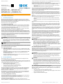
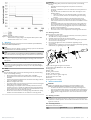
HINWEIS
Bei der Auslegung des Einschaltstroms Abbildung 1 beachten.
Abbildung 1: Auslegung des Einschaltstroms
Es muss sichergestellt werden, dass die Versorgungsspannung von
+7 V bis +12 V an der DSL-Dose des separaten sHub
®
-Systems
anliegt.
4 Montage
Dieses Kapitel beschreibt die Durchführung der Montage des Motor-Feedback-
Systems EDS35-0V/ EDS35-2V/EDM35-0V/EDM35-2V.
HINWEIS
Abhängig von der Motorkonstruktion kann es erforderlich sein, die elektrische
Installation vor der mechanischen Montage durchzuführen.
HINWEIS
Ist eine Demontage des Motor-Feedback-Systems EDS35-0V/ EDS35-2V/
EDM35-0V/EDM35-2V erforderlich, so sind die Montageschritte in umgekehr‐
ter Reihenfolge durchzuführen.
HINWEIS
Während der Montage keine Schläge und Stöße auf das Motor-Feedback-Sys‐
tem geben.
HINWEIS
Um Verunreinigungen des Encoders zu minimieren bzw. zu vermeiden, muss
die Montage in einem Schritt vorgenommen werden. Für die Dauer der Lage‐
rung muss die Kappe (7) leicht auf den Encoder aufgedrückt werden.
4.1 Sicherheit
WARNUNG
Für die Montage der seitlichen Befestigungsschrauben (2) und der konischen
Befestigungsschraube (1) folgende Sicherheitshinweise beachten:
•
Grenzflächenpressung vom Motorschild: > 200 MPa.
•
Der Werkstoff der Motorwelle muss einer Mindestzugfestigkeit von
530 MPa genügen.
•
Gewindebohrungen gemäß DIN 13 mit Senkungen gemäß DIN 76 min.
1,05 × Gewindedurchmesser.
•
Festigkeitsklasse mindestens 8,8.
•
Einschraubtiefe muss mindestens 5 Gewindegänge betragen; Schrau‐
benlänge entsprechend den Einbauverhältnissen wählen.
•
Anzugsmoment gilt bei bereits vorhandenem Gewinde im Motorlager‐
schild. Bei nicht vorhandenem Gewinde ist das zusätzliche Furchmo‐
ment abhängig vom Material des Motorlagerschildes und dem Boh‐
rungsdurchmesser für die Befestigungsschraube (2) zu berücksichtigen.
•
Schraubverbindungen mit flüssiger Schraubensicherung gegen Lösen
sichern. Federscheiben und Zahnscheiben sind als Schraubensicherung
nicht ausreichend.
WARNUNG
Für die bei der Montage eingesetzte Zubehör-Schraube (1) folgende Sicher‐
heitshinweise beachten:
•
Bei der Schraube (1) 4093779 ist keine zusätzliche Schraubensiche‐
rung erforderlich.
•
Die Schraube (1) 4093779 darf aufgrund ihrer Beschichtung nur ver‐
wendet werden, wenn das Haltbarkeitsdatum nicht abgelaufen ist.
•
Schraube (1) 4093779 nur einmal verwenden. Nach der Demontage
des Motor-Feedback-Systems:
°
an der Antriebswelle betroffene Gewinde von Reststoffen reinigen.
°
bei erneuter Montage eine neue (ungebrauchte) Schraube am
Gewinde verwenden.
•
Wenn das Material, die Oberflächenbeschaffenheit und die exakten
Abmessungen des Innengewindes der Motorwelle nicht sicher bekannt
sind, muss die Eignung der Verbindung für die Serienproduktion durch
Tests sichergestellt werden.
•
Das Innengewinde der Motorwelle muss schmutz-, fett- und gratfrei
sein. Eine Gewindetoleranz 6 H ist zu gewährleisten. Geometrie des
Gewindes siehe Anbauvorschlag (Kegel des Gewindeeinlaufs analog
Anbauvorschlag).
•
Die Schraube sollte in einer Bewegung, ohne axialen Vorschub montiert
werden.
•
Aushärtungszeit: 6 Stunden bei Raumtemperatur. Endfestigkeit nach
24 Stunden.
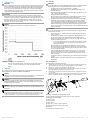
4.2 Montageablauf
Kundenseitige Antriebswelle blockieren.
1. Abdeckung (6) vorsichtig vom Encoder (8) entfernen. Falls erforderlich, die
Torx-Schraube T08 (7) mit einem Schraubendreher herausdrehen.
2. Encoder (8) vorsichtig auf die Motorwelle schieben.
3. Encoder (8) drehen, bis die Löcher in der Drehmomentstütze (9) über den
Befestigungslöchern des Motors positioniert sind.
4. Schraube (1) 4093779 vormontieren und festziehen. Anzugsdrehmoment:
3,1 ± 0,3 Nm.
5. Drehmomentstütze (9) durch wechselweises Festziehen von 2 Schrauben
M3 (2) am Motor anbringen. Anzugsdrehmoment: 0,8 ± 0,08 Nm.
2
2
1
7
6
3
4
5
8
9
10
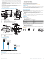
Abbildung 2: Montage/Demontage Konuswelle
1 Konische Befestigungsschraube (M4 × 48, Torx T15), 4093779
2 Befestigungsschraube M3
3 sHub
®-
Leitung
4 sHub
®-
Stecker
5 sHub
®
-Dose
6 Kappe (rot: multiturn, grün: singleturn)
7 Befestigungsschraube/Kappe (Torx T08)
8 Encoder
9 Federteller/Drehmomentstütze
8025370//19.05.2020/de, en EDS35-0V.../EDS35-2V.../EDM35-0V.../EDM35-2V... | SICK 2

5 Elektrische Installation
WARNUNG
Im Zusammenhang mit der elektrischen Installation des Motor-Feedback-Sys‐
tems EDS35-0V/EDS35-2V/EDM35-0V/EDM35-2V die folgenden Punkte
beachten:
•
Beim Anschließen der Sensoren die Montageanleitungen für das
externe Antriebssystem oder das übergeordnete Steuerungssystem
beachten.
•
Beim Herstellen bzw. Trennen der elektrischen Anschlüsse am Motor-
Feedback-System darf niemals Spannung anliegen. Anderenfalls
besteht die Gefahr eines Gerätedefekts.
•
Sicherstellen, dass die betroffenen Maschinen/Systeme während der
Montage abgeschaltet sind.
5.1 Schirmanbindung
HINWEIS
Für einen störungsfreien Betrieb ist eine geeignete Schirmanbindung des
Encoders an Masse bzw. an den Motorschirm des Motors erforderlich. Der
Encoder ist über die Schrauben (2) mit dem Motorgehäuse verbunden.
5.2 Schnittstellen anschließen
Position Stecker/Dose
Typ Stecker Dose
sHub
®
4 5
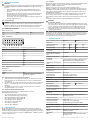
5.2.1 sHub
®
-Dose
Abbildung 3: JST BM08B-GHS-TBT – Steckerbelegung geräteseitig
PIN Signal
1 US+
2 GDN
3 DSL-
4 DSL+
5 RxD+
6 RxD-
7 TxD-
8 TxD+
5.2.2 Empfohlene Komponenten
Kabelstecker
empfohlene Stecker
Stecker Typ
sHub
®
JST GHR-08V-S (Gehäuse) SSHL-002GA1-
P0.2 (Kontakt, vergoldet)
5.3 Vorgehensweise bei der elektrischen Installation
1. Falls erforderlich, vorsichtig die Abdeckung (6) vom Encoder (8) entfernen.
Falls erforderlich, die Torx-Schraube T08 (7) mit einem Schraubendreher
herausdrehen.
2. Den Stecker für den sHub
®
-Litzensatz (4) in die sHub
®
-Dose (5) am Encoder
stecken – ausreichend tief, damit er einrastet, aber ohne mechanische
Belastung.
3. Die Abdeckung (6) montieren und die Torx-Schraube T08 (7) festziehen.
Anzugsdrehmoment: 0,5 ± 0,05 Nm.
5.4 Signale des Motor-Feedback-Systems
Das Motor-Feedback-System kann folgende Signale emittieren:
HIPERFACE DSL
®
Schnittstelle:
•
US+: Versorgungsspannung für den Encoder
•
GND: Versorgungsspannung für den Encoder
•
DSL-: RS-485 Negatives Datensignal DSL
•
DSL+: RS-485 Positives Datensignal DSL
•
RxD+: RS-422 / Sensor Hub Data
•
RxD-: RS-422 / Sensor Hub Data
•
TxD-: RS-422 / MFB Data
•
TxD+: RS-422 / MFB Data
6 Inbetriebnahme
Bei der Inbetriebnahme des Motor-Feedback-Systems EDS35-0V/ EDS35-2V/
EDM35-0V/EDM35-2V wird davon ausgegangen, dass der Hersteller des verbun‐
denen Antriebssystems alle für dessen Auslegung geltenden Sicherheitsanforde‐
rungen, die in der technischen Information „HIPERFACE DSL
®
MASTER“ beschrie‐
ben sind, eingehalten hat.
6.1 Kontrollen
Bei Inbetriebnahme ist sicherzustellen, dass ein sicheres Motor-Feedback-System
EDS35-2 / EDM35-2 und nicht ein Standard-Motor-Feedback-System
EDS35-0 / EDM35-0 eingesetzt wird.
Darüber hinaus muss bei einem sicheren Motor-Feedback-System
EDS35-2 / EDM35-2 nach durchgeführtem Encoder-RESET (Hardware-oder Soft‐
ware-RESET) das POST-Bit (Power-On-Self-Test) gesetzt sein. Das POST-Bit kann
nach erfolgter positiver Prüfung quittiert werden (siehe technische Information
„HIPERFACE DSL
®
MASTER“).
Bei Änderung des Positionsoffsets des Motor-Feedback-Systems über die Res‐
source 101h („Position setzen“) oder 108h („Fabrikeinstellungen“) muss
anschließend verifiziert werden, dass der Sensor den gewünschten Positionswert
liefert.
Im Betrieb sind keine weiteren prüfenden Maßnahmen erforderlich.
WARNUNG
Die Lebensdauer beachten!
Die sicheren Motor-Feedback-Systeme EDS35-2/EDM35-2 haben eine maxi‐
male Lebensdauer, nach der sie in jedem Fall außer Verkehr gebracht werden
müssen. Zusätzlich zur Gebrauchsdauer muss auch die Lebensdauer der
Lager berücksichtigt werden. Der Parameter, der in Abhängigkeit von der
Anwendung als erster erreicht wird, bestimmt den Zeitpunkt der Außerbe‐
triebsetzung des Systems.
Das Baujahr des Motor-Feedback-Systems wird im Geräteetikett bzw. im Verpa‐
ckungsetikett als ein vierstelliger Code angegeben (yyww). Die beiden ersten Stel‐
len (yy) bezeichnen das Baujahr (ohne Jahrhundert), die beiden letzten Stellen
(ww) die Kalenderwoche des letzten Herstellungsprozesses.
7 Technische Daten
Singleturn Multiturn
Performance
Auflösung pro Umdrehung 20 Bit 24 Bit 20 Bit 24 Bit
Signalrauschen (σ)
1
± 3“ ± 1“ ± 3“ ± 1“
Systemgenauigkeit
2
± 50“ ± 25“ ± 50“ ± 25“
Anzahl der absolut nachweisbaren
Umdrehungen
1 4.096
Drehzahl beim Einschalten und
Reset des Motor-Feedback-Sys‐
tems
3
≤ 6.000 min
-1
Verfügbarer Speicherbereich 8.192 Bytes
Schnittstelle
Codesequenz Erhöhung bei Drehung der Welle. Im Uhrzeigersinn mit
Blick in Richtung des „A“ (siehe Maßzeichnung).
2
HIPERFACE DSL
®
Schnittstellensi‐
gnale
4
H-DSL 2-adrig: digital, RS485 kombiniert mit Strom
Initialisierungszeit
5
Max. 500 ms (angeschlossen am sHub
®
)
Elektrische Daten
Betriebsspannungsbereich/Versor‐
gungsspannung
7 V bis 12 V
Einschaltdauer Spannungsrampe
7
Max. 180 ms
Leistungsaufnahme
8
Max. 2,0 W (Vs = 7 V bis 12 V)
Mechanische Daten Gelten für EDS/EDM35 + sHub
®
Abmessungen Siehe Maßzeichnung
Gewicht Max. 100 g
Trägheitsmoment des Rotors 5 gcm²
Betriebsdrehzahl Max. 12.000 min
–1
Max. 9.000 min
–1
Max. Winkelbeschleunigung 250.000 rad/s²
Anlaufdrehmoment bei 20 °C ≤ 0,4 Ncm
Zulässige axiale Wellenbewegung
(statisch + dynamisch)
± 1 mm
Zulässige radiale Wellenbewegung
(dynamisch)
± 0,025 mm
Lebensdauer der Kugellager 50.000 h bei 6.000 U/min (bei einem definierten
Messpunkt von 70 °C)
Umgebungsbedingungen
Betriebstemperaturbereich
9
–40 bis +115 °C
Lagertemperaturbereich –40 bis +125 °C (ohne Verpackung)
Höhenlage beim Betrieb ≤ 2.000 m über dem Meeresspiegel. (80 kPa)
Relative Luftfeuchte/Betauung 90 % (Betauung nicht zulässig)
Widerstandsfähigkeit gegenüber
Schocks
1.000 m/s
2
/6 ms (gemäß EN 60068-2-27:2009)
Widerstandsfähigkeit gegenüber
Vibration
500 m/s
2
/10 … 2.000 Hz (gemäß
EN 60068-2-6:2008)
Schutzklasse
10
IP40 gemäß IEC 60529:2014
EMV
11
Gemäß EN 61000-6-2:2016, EN 61000-6-4:2006,
IEC 6100-6-7:2014
8025370//19.05.2020/de, en EDS35-0V.../EDS35-2V.../EDM35-0V.../EDM35-2V... | SICK 3

Nachfolgende sicherheitstechnische Kenngrößen nur gültig bei zertifizierten Versionen
EDS35-2/EDM35-2
Sicherheits-Integritätslevel
12
,
13
SIL2 (IEC 61508:2011), SILCL3 (EN 62061:2010)
Systematische Eignung
13
SC3 (IEC 61508:2011)
Kategorie 3 (EN ISO 13849-1:2015)
Testrate 24 h
Maximale Anforderungsrate
14
216 µs
Performance Level PL d (EN ISO 13849-1:2015)
Sicherheitsgerichtete Auflösung 13 Bit
Sicherheitsgerichtete Informationen Sichere absolute Singleturn-Position
Sicherheitsgerichtete Genauigkeit
15
0,045°
PFHD: Wahrscheinlichkeit eines
gefahrbringenden Ausfalls
16
31 * 10
-9
1/h
TM (Gebrauchsdauer) 20 Jahre (EN ISO 13849-1:2015)
1
Wiederholstandardabweichung nach DIN 1319-1:1995.
2
Nach DIN 1319-1:1995: Die Position der oberen und unteren Fehlergrenze hängt von
der Installationssituation ab; der angegebene Wert bezieht sich auf eine symmetrische
Position.
3
Multiturn-Informationen sind nicht sicherheitsgerichtet.
4
Zur Verbindung mit einem Antriebsregler muss eine Safety-Variante des DSL Master IP-
Core im Regler implementiert werden, siehe die technische Information „HIPERFACE
DSL
®
MASTER“.
5
Ab Erreichen einer zulässigen Betriebsspannung.
6
Ohne Toleranz des Sensors; bei –17 °C ... +167 °C: NTC ± 2K (103 GT); PTC ± 3K
(PT1000, KTY 84/130) Für die Umrechnungsfunktion (RID 201h, MANAGIO) siehe die
technische Information „HIPERFACE DSL
®
MASTER“
7
Dauer der Spannungsrampe zwischen 0 V ... 7 V
8
Bei Verwendung der vorgeschlagenen Eingangsschaltung, wie in der technischen Infor‐
mation „HIPERFACE DSL
®
MASTER“ beschrieben.
9
Für die Messung der Arbeitstemperatur muss der definierte Messpunkt (4) am Motor-
Feedback-System verwendet werden (siehe Maßzeichnung, Abbildung 6).
10
IP54 erforderlich im eingebauten Zustand.
11
Die EMV entsprechend den aufgeführten Normen wird gewährleistet, wenn das Motor-
Feedback-System bei aufgestecktem Gegenstecker über einen Kabelschirm mit dem
zentralen Erdungspunkt des Motorreglers verbunden ist. Bei Verwendung anderer
Schirmkonzepte muss der Anwender eigene Tests durchführen. Gerät der Klasse A.
12
Für detaillierte Informationen zur exakten Auslegung ihrer Maschine/Anlage setzten Sie
sich bitte mit Ihrer zuständigen SICK-Niederlassung in Verbindung.
13
Siehe Kapitel 2.2.
14
Der Benutzer muss Tests entsprechend dem Sicherheitsintegrationshandbuch ausfüh‐
ren.
15
Die Sicherheitsgerichtete Genauigkeit gibt die maximale Positionsfehlergrenze an, mit
der die Sicherheitsfunktionen unterstützt werden können.
16
Bei 60 °C Umgebungstemperatur.
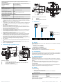
8 Maßzeichnungen (alle Maße in mm)
1
3 4
2
41±0,5
5±0,5
6,5
M4
0,01 A B
A
C0,01
1:3
9,462°±3΄
10±0,5
B
3
9±0,1
Ø3,25 ± 0,05
(2x)
Ø 35 ±
0,5
max. 36
37,4±0,2
40,6±0,2
max. 46,3
Abbildung 4: Maßbild
1
Abstützung der Encoder Welle
2
Konische Befestigungsschraube (M4 x 48, Torx T15), 4093779
3
Messpunkt für Vibrationen
4
Messpunkt für Betriebstemperatur
1
1
2
3
min. 6
1,8 D
D
A
B
BA
AØ 0,2
2
0,2 A
Rz 6,3
Rz 6,3
Ø 6,5
min. Ø 8
max. Ø 15
1:3
60°
0,02
0,02 C
9,462° ±3΄
0,4
3,4
7,4
+0.2
min.10
C
Ø 5,5
Ø 38 (180°)
Ø 40 (180°)
0,2 A
M3
(2x)
M3
(2x)
0,2 A
M4 6H
Abbildung 5: Anbauvorgabe Konuswelle
1
Statisch
2
Dynamisch
3
Abstützung der Antriebswelle
9 Bestelldaten
durchgeführt von
Singleturn
Mechanisches Getriebe - Multiturn
Sicherheitsniveau
nicht sicher
SIL2
Auflösung
20 Bits je Drehung
24 Bits je Drehung
S
M
0
2
2
2
0
4
E D 3 5 - V F O A O A
Abbildung 6: Bestellcode
10 Zubehör
Die Schraube-Konus M4 × 48 (Art.-Nr.: 4093779) ist in verschiedenen Packungs‐
größen erhältlich:
•
10 Stück (Art.-Nr.: 2103274)
•
100 Stück (Art.-Nr.: 2103272)
•
500 Stück (Art.-Nr.: 2103244)
Litzensatz ungeschirmt (Art.-Nr.: 2115196)
Litzensatz geschirmt (Art.-Nr.: 2112927)
Zubehör finden Sie in der Produktinformation auf www.sick.com
11 Instandhaltung
Das sichere Motor-Feedback-System ist wartungsfrei. Bei Defekt ist keine Repara‐
turmöglichkeit vorgesehen. Bitte kontaktieren Sie uns auf jeden Fall bei defekten
Geräten, damit eine Analyse der Ausfallursache erfolgen kann.
12 Außerbetriebnahme
Umweltgerechtes Verhalten
Das Motor-Feedback-System ist so konstruiert, dass es die Umwelt so wenig wie
möglich belastet. Es verbraucht nur ein Minimum an Energie und natürlichen Res‐
sourcen.
Handeln Sie auch am Arbeitsplatz immer mit Rücksicht auf die Umwelt.
Beachten Sie deshalb die folgenden Informationen zur Entsorgung.
12.1 Entsorgung
Entsorgen Sie unbrauchbare oder irreparable Geräte immer gemäß den jeweils
gültigen landesspezifischen Abfallbeseitigungsvorschriften.
13 Anhang
13.1 Lieferumfang
•
Sicheres Motor-Feedback-System
•
Grundlegende Sicherheitshinweise, Artikelnummer 8014060
•
Betriebsanleitung
Typ Artikel-Nr.
EDM35-0VF0A024A 1106846
EDM35-2VF0A024A 1106851
Die sicheren Motor-Feedback-Systeme EDS35-2 / EDM35-2 wurden gemäß fol‐
genden Richtlinien hergestellt:
8025370//19.05.2020/de, en EDS35-0V.../EDS35-2V.../EDM35-0V.../EDM35-2V... | SICK 4

•
Maschinenrichtlinie 2006/42/EG
•
EMV-Richtlinie 2014/30/EG
Die vollständige EU-Konformitätserklärung finden Sie auf der SICK Homepage im
Internet:
www.sick.com
O P E R A T I N G I N S T R U C T I O N S
e n
Safe motor feedback systems
1 About this document
Please read these operating instructions carefully before using the safe motor
feedback system or mounting it, putting it into operation or servicing it. The manu‐
facturer can only guarantee the safety function if these operating instructions are
followed consistently.
This document is an original document.
1.1 Purpose of this document
These operating instructions provide qualified technical personnel of the machine
manufacturer or the machine operator with instructions regarding the safe mount‐
ing, electrical installation, commissioning, operation, maintenance and decom‐
missioning of the safe motor feedback system EDS35-2/EDM35-2.
These operating instructions must be made available to all those who work with
the safe motor feedback system.
Furthermore, planning and using safety-oriented sensors such as the safe motor
feedback system EDS35-2/EDM35-2 also requires technical skills that are not
covered in this document. The official, legal and safety-relevant regulations for
mounting and operating the safe motor feedback system EDS35-2/EDM35-2
must always be complied with.
1.2 Symbols and document conventions
WARNING
A safety note informs you of real-world specifications for safely mounting and
installing the safe motor feedback system EDS35-2/EDM35-2. This is
intended to protect you against accidents. Read and follow the safety notes
carefully.
NOTE
Indicates useful tips and recommendations.
b Instructions requiring specific action are indicated by an arrow. Carefully read
and follow the instructions for action.
1.3 Associated documents
•
For EDS35-0V/EDM35-0V: “HIPERFACE DSL
®
MASTER Integration Manual”
technical information, part number 8017595, as of 24.03.2020 (or newer).
•
For EDS35-2V/EDM35-2V: „HIPERFACE DSL
®
MASTER Safety Integration
Manual“ technical information, part number 8017596, as of 17.01.2019 (or
newer).
•
Specification of dangerous failure is described in “HIPERFACE DSL
®
MAS‐
TER” technical information.
2 Safety Information
This chapter concerns your own safety and the safety of the system operator.
2.1 General safety notes
The national and international legal specifications apply to the installation and
use of the motor feedback system, to its commissioning and to technical inspec‐
tions repeated at regular intervals, in particular:
•
the Machinery Directive 2006/42/EC
•
the Equipment Directive 2009/104/EC
•
work safety regulations and safety regulations
•
any other relevant safety regulations
The manufacturer and operator of the machine, on which the safe motor feed‐
back system EDS35-2/EDM35-2 is used, are responsible for coordinating and
complying with all applicable safety specifications and regulations, in cooperation
with the relevant authorities.
The manufacturer of the drive system connected must have complied with the
safety requirements for the drive system design described in the integrationman‐
ual, “HIPERFACE DSL
®
MASTER”.
2.2 Intended use
The motor feedback system is ideal for the dynamic and precise operation of
servo-control circuits, due to its equipment.
The overall system, consisting of encoder, evaluation system, servo inverter and
motor, forms a control circuit.
The safety-oriented use of safe motor feedback systems EDS35-2/EDM35-2 with
a HIPERFACE DSL
®
interface concerns application in combination with servo sys‐
tems that work with three-phase AC synchronous motors and alternatively AC
asynchronous motors.
The following information can be derived from the digital position signals of the
motor feedback system linked directly to a motor shaft:
•
(Rotational) speed information and commuting information in AC synchro‐
nous motors
•
(Rotational) speed information in asynchronous motors
The safe motor feedback system EDS35-2/EDM35-2 can be used in conjunction
with a drive system in accordance with IEC 61800-5-2, in safety applications up to
category 3 and PL d in accordance with EN ISO 13849 or SIL2 in accordance with
IEC 61508 or SIL CL3 in accordance with EN 62061.
The safety integrity level of the encoder is SIL 2. The systematic capability of the
encoder is SC 3. Only when applied in redundant architecture, the encoder can be
utilized for SIL 3 applications, otherwise, i.e. when used standalone, it shall be uti‐
lized maximum for SIL 2 applications.
It fulfills the requirements of the Machinery Directive 2006/42/EC and provides
support for the drive system in ensuring:
•
The safety functions, based on the safe absolute position information
•
The safety functions, based on the incremental position information
The safety functions only apply for a single motor revolution (singleturn).
In the case of safety functions that are based on the safe multiturn absolute posi‐
tion, the motor feedback system only supplies one channel without safety-related
diagnostics upon being switched on. The user must implement a second chan‐
nel by using other measures.
The user can provide this second channel by saving the position of the motor
feedback system before switching it off and comparing it to the starting position of
the motor feedback system, when switching it on the next time.
Use for multiturn absolute position safety-related purposes is possible only, if the
values match. Otherwise, the user must carry out a reference run. Without a sec‐
ond channel for the multiturn absolute position, a reference run must be carried
out each time, the motor feedback system is switched on to confirm the absolute
position.
The motor feedback system is not able to create a safe state for the drive system
independently. The drive system has to create the safe state as a response to an
error displayed by the motor feedback system.
WARNING
The safe motor feedback system EDS35-2/EDM35-2 shall be used only
within the limits of the prescribed and specified technical data, dimensions
and tolerances of the dimensional drawings and operating conditions, and
the specified tightening torques must be complied with.
If used in any other way or if alterations are made to the device – including in
the context of mounting and installation – this will render void any warranty
claims directed to SICK STEGMANN GmbH.
2.3 Improper use
The motor feedback system must be mounted and adjusted exactly in accordance
with the specifications of the installation instructions. Every faulty installation or
faulty adjustment of the encoder may impair the specified functions and data;
partial restriction or a total failure of the specified safety functions cannot be
ruled out in individual cases.
WARNING
If stimulations in the vicinity of the resonance frequencies cannot be reliably
ruled out in the application, suitable tests must be carried out for the entire
drive system during the initial commissioning of the system. Suitable reme‐
dial measures must be incorporated.
WARNING
Violations of the specified accuracy of the position value in the vicinity of the
resonance frequencies can occur, due to physical restraints. If the mechani‐
cal stimulation in the vicinity of the resonance frequencies has a very high
amplitude, faults or failures of the specified safety functions can occur. We
highly recommend to avoid operation in the vicinity of the resonance frequen‐
cies or at least to limit the amplitude.
2.4 Requirements for the qualification of personnel
The safe motor feedback system EDS35-2/EDM35-2 may be mounted, put into
operation, checked, maintained or used only by qualified safety personnel. A qual‐
ified person
•
is someone who has taken part in adequate technical training
•
has been instructed by a machine operator in machine operation and the
applicable safety guidelines and
•
has access to these operating instructions.
3 Project planning
WARNING
The supply voltage must be generated by PELV systems (EN 50178) and shall
be limited to 15 VDC by external means. The motor feedback system corre‐
sponds to protection class III according DIN EN 61140. If the supply voltage is
not generated by the PELV systems, other measures must be found that will
guarantee that live parts are safely separated.
WARNING
Use only temperature sensors with doubled or reinforced insulation according
to protection class II according to IEC 61140:2016 because there is no gal‐
vanic separation of the temperature sensor in the motor feedback system.
The power supply unit current used for the motor feedback system must be
limited to a maximum continuous current of 1 A, either by the power supply
unit itself or using a fuse.
NOTE
When configuring the switch-on current, observe Figure 1.
8025370//19.05.2020/de, en EDS35-0V.../EDS35-2V.../EDM35-0V.../EDM35-2V... | SICK 5

Figure 1: Configuring the switch-on current
Ensure that the supply voltage to the separate sHub
®
system’s DSL
female contact is from +7 V ... +12 V.
4 Mounting
This chapter describes the mounting of the motor feedback system EDS35-0V/
EDS35-2V/EDM35-0V/EDM35-2V.
NOTE
Depending on the motor design, it may be necessary to perform the electrical
installation before the mechanical mounting.
NOTE
If the motor feedback system EDS35-0V/ EDS35-2V/EDM35-0V/EDM35-2V
has to be removed, the mounting steps are to be carried out in reverse order.
NOTE
No impacts or shocks are permitted during the mounting of the motor feed‐
back system.
NOTE
To minimize and avoid any pollution of the encoder the mounting shall be
done in one step. During storage time the cap (7) has to be pressed slightly
on the encoder.
4.1 Safety
WARNING
Note the following safety notes for the side fixing screws (2) and cone fixing
screw (1) used during mounting:
•
Permissible surface pressure from engine plate > 200 MPa.
•
The material of motor shaft must have a minimum tensile strength of
530 MPa.
•
Thread holes according to DIN 13 with counterbore according to DIN 76
min. 1.05 x diameter of thread.
•
Minimum strength class of 8.8.
•
The screw-in depth must be at least 5 thread turns; select screw lengths
appropriate for the installation conditions.
•
The tightening torque applies if there is already a thread in the motor
end plate. If there is no thread, the additional rolling torque depending
on the material of the motor end plate and on the drill diameter for the
fixing screw (2) must also be taken into account.
•
Secure screw connections from loosening using screw adhesive. Spring
washers and toothed washers are not sufficient for securing screws.
WARNING
Note the following safety notes for the accessory screw (1) used during
mounting:
•
No additional screw locking device is required for the screw (1)
4093779.
•
The screw (1) 4093779 must not be used after the use-by date due to
its coating.
•
Only use the screw (1) 4093779 one time. After removing the motor
feedback system:
°
Clean the residue off of the affected threads on the drive shaft.
°
Use a new (unused) screw on the thread during the remounting
process.
•
As the material, surface condition, and precise dimensions of the
female thread of the motor shaft have not been ascertained, control
tests must be carried out to ensure the connection is suitable for series
production.
•
The female thread of the motor shaft must be free of dirt, grease and
burrs. A thread tolerance of 6H must be ensured. For the geometry of
the thread, see the mounting suggestion (taper of the thread infeed in
line with mounting suggestion).
•
Mount the screw in one movement and without axial feed.
•
Cure time: 6 hours at room temperature. Final strength after 24 hours.
4.2 Mounting procedure
Block the customer’s drive shaft.
1. Carefully remove the cover (6) from the encoder (8). If necessary, undo the
Torx T08 screw (7) using a screwdriver.
2. Carefully push the encoder (8) onto the motor shaft.
3. Turn the encoder (8) until the holes in the stator coupling (9) are positioned
over the motor’s mounting holes.
4. Pre-mount and tighten the screw (1) 4093779. Tightening torque:
3.1 ± 0.3 Nm.
5. Attach the stator coupling (9) to the motor end plate by alternately tightening
2 M3 screws (2). Tightening torque: 0.8 ± 0.08 Nm.
2
2
1
7
6
3
4
5
8
9
10
Figure 2: Mounting/removing the conical shaft
1 Cone fixing screw (M4X48, Torx T15), 4093779
2 M3 fixing screw
3sHub
®
cable
4 sHub
®
male connector
5 sHub
®
female connector
6 Cap (red: multi turn, green: single turn)
7 Cap fixing screw (Torx T08)
8 Encoder
9 Spring plate stator coupling
5 Electrical Installation
WARNING
Observe the following points in relation to electrical installation of the
EDS35-0V/ EDS35-2V/EDM35-0V/EDM35-2V motor feedback system.
•
To connect the sensors, refer to the corresponding mounting instruc‐
tions for the external drive system or for the higher-order control system.
•
Never establish or remove electrical connections to the motor feedback
system with the voltage switched on, since that could result in a faulty
device.
5.1 Shielding connection
NOTE
A suitable encoder shield connection to the ground or to the motor shield is
required for a smooth operation. The encoder is connected to the motor hous‐
ing via the screws (2).
5.2 Connecting interfaces
Male/female connector position
Type Male connector Female connector
sHub
®
4 5
8025370//19.05.2020/de, en EDS35-0V.../EDS35-2V.../EDM35-0V.../EDM35-2V... | SICK 6

5.2.1 sHub
®
female connector
Figure 3: JST BM08B-GHS-TBT - Device pin assignment
Pin Signal
1 US+
2 GND
3 DSL-
4 DSL+
5 RxD+
6 RxD-
7 TxD-
8 TxD+
5.2.2 Recommended components
Cable connector
recommended connector
Connector Type
sHub
®
JST GHR-08V-S (Housing) SSHL-002GA1-
P0.2 (Contact, gold-plated)
5.3 Electrical Installation Procedure
1. If necessary, carefully remove the cover (6) from the encoder (8). If neces‐
sary, undo the Torx T08 screw (7) using a screwdriver.
2. Insert the male connector for the set of sHub
®
stranded wires (4) into the
sHub
®
female connector (5) on the encoder far enough that it clicks into
place, but without mechanical stress.
3. Mount the cover (6) and tighten the Torx T08 screw (7). Tightening torque:
0.5 ± 0.05 Nm.
5.4 Motor feedback system signals
The motor feedback system has the following signals:
HIPERFACE DSL
®
interface:
•
US+: Supply voltage for the encoder
•
GND: Supply voltage for the encoder
•
DSL-: RS-485 negative data signal DSL
•
DSL+: RS-485 positive data signal DSL
•
RxD+: RS-422 / Sensor Hub Data
•
RxD-: RS-422 / Sensor Hub Data
•
TxD-: RS-422 / MFB Data
•
TxD+: RS-422 / MFB Data
6 Commissioning
To commission the motor feedback system EDS35-0V/ EDS35-2V/EDM35-0V/
EDM35-2V, it is assumed that the manufacturer of the connected drive system
has complied with the safety requirements for the drive system design, as
described in the “HIPERFACE DSL
®
MASTER” technical information.
6.1 Checking
During commissioning ensure that an EDS35-2 / EDM35-2 safe motor feedback
system is used and not an EDS35-0 / EDM35-0 standard motor feedback system.
In addition, the POST bit (Power-On-Self-Test) must be set for an EDS35-2 /
EDM35-2 safe motor feedback system after an encoder RESET (hardware or soft‐
ware RESET). The POST bit can be acknowledged after a positive thorough check
(see “HIPERFACE DSL
®
MASTER” technical information).
If the position offset of the motor feedback system is changed using the 101h
(“Set position”) resource or the 108h (“Factory settings”) resource, it is then nec‐
essary to verify that the sensor is providing the required position value.
Further inspection measures are not required during operation.
WARNING
Observe the service life!
The EDS35-2/EDM35-2 safe motor feedback systems have a maximum ser‐
vice life, after which they must always be put out of service. The bearing ser‐
vice life must be taken into account in addition to the mission time. The para‐
meter which is first reached depending on the application determines the
time when the system must be taken out of operation.
The year of manufacture of the motor feedback system is specified on the device
label and/or on the packaging label as a four digit code (yyww). The first two digits
(yy) represent the year (without the century), and the last two digits (ww) repre‐
sent the calendar week of the last manufacturing process.
7 Technical data
Singleturn Multiturn
Performance
Resolution per revolution 20 Bit 24 Bit 20 Bit 24 Bit
Position noise (σ)
1
± 3“ ± 1“ ± 3“ ± 1“
System accuracy
2
± 50“ ± 25“ ± 50“ ± 25“
Number of the absolute ascertain‐
able revolutions
1 4,096
Speed when switching on and reset‐
ting the motor feedback system
3
≤ 6,000 min
-1
Available memory area 8,192 bytes
Interface
Code sequence Increasing on rotation of shaft. Clockwise while looking
towards "A" (see dimensional drawing).
2
HIPERFACE DSL
®
interface signals
4
2-wire H-DSL: Digital, RS485 combined with Power
Initialization time
5
Max. 500 ms (connected with sHub
®
)
Electrical data
Operating voltage range/supply
voltage
7 V … 12 V
Switch on timing voltage ramp
7
Max. 180 ms
Power consumption
8
Max. 2.0 W (Vs = 7 V … 12 V)
Mechanical data Valid for EDS/EDM + sHub
®
Dimensions See dimensional drawing
Mass Max. 100g
Rotor moment of inertia 5 gcm²
Operating speed Max. 12,000 min
–1
Max. 9,000 min
–1
Max. angular acceleration 250,000 rad/s²
Start-up torque at 20°C ≤ 0.4 Ncm
Permissible shaft movement axial
(static + dynamic)
± 1 mm
Permissible shaft movement radial
(dynamic
± 0.025 mm
Service life of ball bearings 50,000 h at 6,000 rpm (at defined measuring point of
70 °C)
Ambient conditions
Operating temperature range
9
–40 … +115 °C
Storage temperature range –40 … +125 °C (without packaging)
Operating altitude ≤ 2,000 m above sea level. (80 kPa)
Relative air humidity/condensation 90 % (condensation impermissible)
Resistance to shocks 1,000 m/s
2
/6 ms (as per EN 60068-2-27:2009)
Resistance to vibrations 500 m/s
2
/10 … 2,000 Hz (as per
EN 60068-2-6:2008)
Protection class
10
IP40 as per IEC 60529:2014
EMC
11
As per EN 61000-6-2:2016, EN 61000-6-4:2006,
IEC 6100-6-7:2014
The following safety-related parameters are only valid for certified versions EDS35-2 /
EDM35-2
Safety integrity level
12
,
13
SIL2 (IEC 61508:2011), SILCL3 (EN 62061:2010)
Systematic capability
13
SC3 (IEC 61508:2011)
Category 3 (EN ISO 13849-1:2015)
Test rate 24 h
Maximum demand rate
14
216 µs
Performance level PL d (EN ISO 13849-1:2015)
Safety related resolution 13 bits
Safety related information Safe Absolute Singleturn Position
Safety related accuracy
15
0.045°
PFHD: probability of dangerous fail‐
ure
16
31 * 10
-9
1/h
TM (mission time) 20 years (EN ISO 13849-1:2015)
1
Repeatability standard deviation according to DIN 1319-1:1995.
2
According to DIN 1319-1:1995, position of the upper and lower error limit depends on
the installation situation, specified value refers to a symmetrical position.
3
Multiturn information is not safety related.
4
A safety variant of the DSL Master IP Core must be implemented in the regulator in order
to connect to a drive controller, see “HIPERFACE DSL
®
MASTER” technical information.
5
Starting from when a permitted supply voltage has been reached.
6
Without sensor tolerance; at –17 °C ... +167 °C: NTC ± 2K (103 GT); PTC ± 3K
(PT1000, KTY 84/130) For recalculation function (RID 201h, MANAGIO) see “HIPERFACE
DSL
®
MASTER” technical information
7
Duration of voltage ramp between 0 V ... 7 V
8
When using the suggested input circuit as described in the “HIPERFACE DSL
®
MASTER”
technical information.
9
The defined measuring point (4) on the motor feedback system must be used for mea‐
suring the operating temperature (see dimensional drawing, Figure 6).
10
IP54 required in installed state.
8025370//19.05.2020/de, en EDS35-0V.../EDS35-2V.../EDM35-0V.../EDM35-2V... | SICK 7

11
According to the listed standards, EMC is guaranteed if the motor feedback system with
mating plug inserted is connected to the central grounding point of the motor controller
via a cable shield. If other shielding concepts are used, users must perform their own
tests. Class A device.
12
For more detailed information on the exact configuration of your machine/unit, please
consult your relevant SICK subsidiary.
13
See chapter 2.2.
14
User must perform testing according to the safety integration manual.
15
The safety-related accuracy indicates the maximum positioning error limit with which the
safety functions can be supported.
16
At 60 °C ambient temperature.
8 Dimensional drawings (all dimensions in mm)
1
3 4
2
41±0,5
5±0,5
6,5
M4
0,01 A B
A
C0,01
1:3
9,462°±3΄
10±0,5
B
3
9±0,1
Ø3,25 ± 0,05
(2x)
Ø 35 ±
0,5
max. 36
37,4±0,2
40,6±0,2
max. 46,3
Figure 4: Dimensional drawing
1
Encoder shaft support
2
Cone fixing screw (M4X48, Torx T15), 4093779
3
Measuring point for vibrations
4
Measuring point for operating temperature
1
1
2
3
min. 6
1,8 D
D
A
B
BA
AØ 0,2
2
0,2 A
Rz 6,3
Rz 6,3
Ø 6,5
min. Ø 8
max. Ø 15
1:3
60°
0,02
0,02 C
9,462° ±3΄
0,4
3,4
7,4
+0.2
min.10
C
Ø 5,5
Ø 38 (180°)
Ø 40 (180°)
0,2 A
M3
(2x)
M3
(2x)
0,2 A
M4 6H
Figure 5: Conical shaft mounting specification
1
static
2
dynamic
3
Drive shaft support
9 Ordering Information
carried out by
Singleturn
Multiturn mechanical gear
Safety Level
non-safe
SIL2
Resolution
20 bits per turn
24 bits per turn
S
M
0
2
2
2
0
4
E D 3 5 - V F O A O A
Figure 6: Ordering code
10 Accessoires
Cone screw M4 x 48 (part number: 4093779) is available in different packaging
units:
•
10 pcs (part number: 2103274)
•
100 pcs. (part number: 2103272)
•
500 pcs. (part number: 2103244)
Set of stranded wires unshielded (part number: 2115196)
Set of stranded wires shielded (part number: 2112927)
You can find accessories in the product information at www.sick.com
11 Maintenance
The safe motor feedback system is maintenance-free. No repair option is provided
in the event of a defect. If any device should become defective, please contact us
so we can perform an analysis to determine the cause of failure.
12 Decommissioning
Protecting the environment
The motor feedback system has been designed to minimize its impact on the envi‐
ronment. It consumes only a minimum of energy and natural resources.
Always act in an environmentally responsible manner at work. For this rea‐
son, please note the following information regarding disposal.
12.1 Disposal
Always dispose of unusable or irreparable devices in accordance with the applica‐
ble waste disposal regulations specific to your country.
13 Appendix
13.1 Scope of Delivery
•
Safe motor feedback system
•
General safety notes, part number 8014060
•
Operating instructions
Type Part no.
EDM35-0VF0A024A 1106846
EDM35-2VF0A024A 1106851
The EDS35-2 / EDM35-2 safe motor feedback systems were manufactured in
accordance with the following directives:
•
Machinery Directive 2006/42/EC
•
EMC Directive: 2014/30/EU
The complete EU Declaration of Conformity is available from the SICK homepage
on the Internet:
www.sick.com
8025370//19.05.2020/de, en EDS35-0V.../EDS35-2V.../EDM35-0V.../EDM35-2V... | SICK 8
-
 1
1
-
 2
2
-
 3
3
-
 4
4
-
 5
5
-
 6
6
-
 7
7
-
 8
8


SICK EDS35-0V Serie Operating instructions
- Type
- Operating instructions
- This manual is also suitable for
Ask a question and I''ll find the answer in the document
Finding information in a document is now easier with AI
in other languages
Related papers
-
SICK EDS35-2.../EDM35-2... Motor feedback system rotary HIPERFACE DSL® Operating instructions
-
-
-
-
-
-
-
-
-
Other documents
-
NewLine SHUB Screen Installation guide
-
 Beckhoff AX8911 Documentation
-
Pepperl+Fuchs PVS58 Operating instructions
-
-
-
Pepperl+Fuchs PSS58 Operating instructions
-
-
Lenze 8200 vector Mounting instructions
-
-
Kollmorgen AKD2G Series Product Safety Manual
