Betrie
bsan‐
leitung
B E T R I E B S A N L E I T U N G d e
Alle Rechte vorbehalten. Irrtümer und Änderungen vorbehalten.
1 Zu diesem Dokument
Bitte lesen Sie diese Betriebsanleitung sorgfältig, bevor Sie mit dem Motor-Feed‐
back-System arbeiten, es montieren, in Betrieb nehmen oder warten.
1.1 Funktion dieses Dokuments
Diese Betriebsanleitung leitet das qualifizierte technische Personal des Maschi‐
nenherstellers bzw. Maschinenbetreibers zur Montage, Elektroinstallation, Inbe‐
triebnahme sowie zum Betrieb und zur Wartung des Motor-Feedback-Systems an.
1.2 Symbole und Dokumentkonventionen
WARNUNG
Weist Sie auf konkrete oder potenzielle Gefahren hin. Dies soll Sie vor Unfäl‐
len bewahren. Lesen und befolgen Sie Warnhinweise sorgfältig!
HINWEIS
Weist Sie auf nützliche Tipps und Empfehlungen hin.
b
Handlungsanweisungen sind durch einen Pfeil gekennzeichnet.
Lesen und befolgen Sie Handlungsanweisungen sorgfältig.
1.3 Zugehörige Dokumente
Technische Information "HIPERFACE DSL
®
", Bestellnummer 8017595, Stand
15.01.2018 (oder neuer).
2 Zu Ihrer Sicherheit
Schalten Sie die Spannung bei allen von der Montage betroffenen Maschinen und
Anlagen ab. Schläge und Stöße auf die Welle unbedingt vermeiden, diese können
zu einem Defekt führen.
Das Gehäuse des Motor-Feedback-System ist mit Befestigungsschrauben verdreh‐
fest mit der kundenseitigen Anflanschung zu verbinden. Je genauer die Zentrie‐
rung für das Motor-Feedback-System ist, desto geringer sind Winkel und Wellen‐
versatz bei der Montage.
Es ist unter EMV-Gesichtspunkten zwingend notwendig, dass das Gehäuse bzw.
der Encoders an Erde angeschlossen wird. Beim EDS35-0 / EDM35-0 mit Konus‐
welle wird das Gehäuse durch den direkten Kontakt mit dem Motorflansch auf
das Motorpotential gezogen.
WARNUNG
Schirmanbindung
Für einen störungsfreien Betrieb unbedingt auf eine geeignete Schirmanbin‐
dung des Motors achten.
Anbauvorbereitung
1. Schutzfolie (soweit vorhanden) auf der Rückseite des Motor-Feedback-Sys‐
tems entfernen.
2. Die Antriebswelle und Welle des Motor-Feedback-Systems ggf. entfetten.
3. Auf Beschädigungen achten.
3 Produktbeschreibung
Encoder der Typen EDS35-0 / EDM35-0 sind Motor-Feedback-Systeme, die auf‐
grund ihrer Ausstattung zum dynamischen und präzisen Betrieb von Servo-Regel‐
kreisen vorgesehen sind.
Das Gesamtsystem, bestehend aus Motor-Feedback-System, Auswertesystem,
Servo-Umrichter und Motor, bildet einen Regelkreis. Aus den Encodersignalen
werden Ist-Werte für Kommutierung, Drehzahl, Drehrichtung und Lage abgeleitet.
Die Übermittlung der Sensorsignale zum Auswertesystem erfolgt über eine
HIPERFACE DSL
®
-Schnittstelle.
WARNUNG
Das Motor-Feedback-System EDS35-0 / EDM35-0 ist kein Sicherheitsbauteil.
Bei geplanter Verwendung als Teil einer Sicherheitsfunktion sind Motor-Feed‐
back-Systeme des Typs EDS35-2 / EDM35-2 einzusetzen.
4 Montage
4.1 Sicherheit
WARNUNG
Für die bei der Montage eingesetzten seitlichen Befestigungsschrauben (2)
und die Konus-Befestigungsschraube (1) folgende Sicherheitshinweise
beachten:
•
Festigkeitsklasse mindestens 8.8
•
Einschraubtiefe muss mindestens 5 Gewindegänge betragen; Schrau‐
benlänge entsprechend den Einbauverhältnissen wählen.
•
Anzugsmoment gilt bei bereits vorhandenem Gewinde im Motorlager‐
schild. Bei nicht vorhandenem Gewinde ist das zusätzliche Furchmo‐
ment abhängig vom Material des Motorlagerschilds und vom Bohrungs‐
durchmesser für die Befestigungsschraube (2) zu berücksichtigen.
•
Schraubverbindungen mit flüssiger Schraubensicherung gegen Lösen
sichern. Federscheiben und Zahnscheiben sind als Schraubensicherung
nicht ausreichend.
WARNUNG
Für die bei der Montage eingesetzte Zubehör-Schraube (1) folgende Sicher‐
heitshinweise beachten:
•
Bei der Schraube (1) 4093779 ist keine zusätzliche Schraubensiche‐
rung erforderlich.
•
Die Schraube (1) 4093779 darf aufgrund ihrer Beschichtung nur ver‐
wendet werden, wenn das Haltbarkeitsdatum nicht abgelaufen ist.
•
Die Schraube (1) 4093779 nur einmal verwenden. Nach der Demon‐
tage des Motor-Feedback-Systems:
°
An der Antriebswelle betroffene Gewinde von Reststoffen reinigen.
°
Bei erneuter Montage eine neue (ungebrauchte) Schraube am
Gewinde verwenden.
•
Da Werkstoff, Oberflächenzustand und genaue Abmessung des Innen‐
gewindes der Motorwelle nicht vorliegen, sind Kontrollversuche notwen‐
dig, um die Serientauglichkeit der Verbindung abzusichern.
•
Das Innengewinde der Motorwelle muss schmutz-, fett- und gratfrei sein.
Eine Gewindetoleranz 6H ist zu gewährleisten. Geometrie des Gewindes
siehe Anbauvorschlag (Kegel des Gewindeeinlaufs analog Anbauvor‐
schlag).
•
Die Schraube sollte in einer Bewegung und ohne axialen Vorschub
moniert werden.
•
Aushärtezeit: 6 Stunden bei Rt. Endfestigkeit nach 24 Stunden.
4.2 Montageablauf
Kundenseitige Antriebswelle blockieren
1. Vorsichtig die Abdeckung (7) vom Encoder (12) entfernen. Eventuell
Schraube Torx T08 (8) mit einem Schraubendreher lösen.
2. Encoder (12) vorsichtig auf die Motorwelle schieben.
3. Den Encoder (12) drehen, bis die Bohrungen der Drehmomentstütze (11)
über den Befestigungslöchern des Motors liegen.
4. Schraube (1) 4093779 vormontieren und festziehen. Anzugsdrehmoment:
3,1 ± 0,3 Nm.
5. Die Drehmomentstütze (11) mit 2 Schrauben M3 (2) am Motorlagerschild
abwechselnd festziehen. Anzugsdrehmoment: 0,8 ± 0,08 Nm.
1
5
2
9
3
4
6
2
ß
à
7
8
á
â
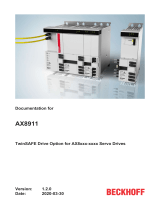
Abbildung 1: Montage Konuswelle
1
Konus-Befestigungsschraube
(M4X48, Torx T15), 4093779
2
Drehmomentenstütze- Befestigungsschraube (M3)
3
DSL-Kabel
4
Temperatursensor-Kabel
5
DSL-Stecker
6
Temperatursensor-Stecker
7
Abdeckung
8
Abdeckung-Befestigungsschraube (Torx T08)
9
DSL-Buchse
ß
Temperatursensor-Buchse
à
Drehmomentstütze
á
Encoder
â
Schirmanschluss
8022478//2018-09-20//de, en EDS35-0… EDM35-0… | SICK 1
8022478//2018-09-20/
www.sick.com
EDS35-0… EDM35-0…
SICK STEGMANN GmbH
Dürrheimer Str. 36
D-78166 Donaueschingen

5 Elektrische Installation
WARNUNG
Beachten Sie die nachfolgenden Punkte für die Elektroinstallation des Motor-
Feedback-Systems EDS35-0 / EDM35-0.
•
Zum Anschluss der Sensoren die entsprechende Montageanleitung des
externen Antriebssystems bzw. der übergeordneten Steuerung beach‐
ten.
•
Elektrische Verbindungen zum Motor-Feedback-System nie bei einge‐
schalteter Spannung herstellen bzw. lösen, da dies sonst zu einem Gerä‐
tedefekt führen kann.
5.1 Schnittstellen anschließen
1 2 3 4
Abbildung 2: DSL-Buchse: Steckerbelegung geräteseitig
Pinbelegung DSL-Buchse
Pin Signal
1 nicht belegt
2 US+ / DSL+
3 GND / DSL-
4 nicht belegt
WARNUNG
Die Versorgungsspannung muss aus PELV-Systemen (EN 50178) erzeugt
werden. Das Motor-Feedback-System entspricht Schutzklasse III nach DIN EN
61140.
Wenn die Versorgungsspannung nicht aus PELV-Systemen erzeugt wird, müs‐
sen benutzerseitig andere Maßnahmen ergriffen werden, die eine sichere
Trennung zu netzspannungsführenden Teilen gewährleisten.
2 1
Abbildung 3: Temperatursensor-Buchse: Steckerbelegung geräteseitig
Pinbelegung Temperatursensor-Buchse
Pin Signal
1 T+
2 T- / GND
b
Falls notwendig, vorsichtig die Abdeckung (7) vom Encoder (12) entfernen.
Eventuell Schraube Torx T08 (8) mit einem Schraubendreher lösen.
b
Den Stecker des DSL Litzensatzes (6) ohne mechanische Belastung in die
DSL-Buchse (10) des Encoders einrasten.
b
Optional: Den Stecker des Temperatursensors (5) ohne mechanische Belas‐
tung in die Temperatursensor-Buchse (9) stecken.
b
Abdeckung (7) montieren und Schraube Torx T08 (8) festziehen. Anzugs‐
drehmoment: 0,5 ± 0,05 Nm.
b
Optional: Schirmlitze des DSL Litzensatzes mittels selbstfurchender
Schraube M2,5x5 am Schirmanschluss (13) anbringen.
5.2 Signale des Motor-Feedback-Systems
Das Motor-Feedback-System EDS35-0 / EDM35-0 verfügt über die folgenden
Signale der HIPERFACE DSL
©
-Schnittstelle:
•
+US / DSL+: Versorgungsspannung des Encoders mit aufmoduliertem positi‐
ven Datensignal. Der Betriebsspannungsbereich am Encoder liegt zwischen
+7 VDC und +12 VDC.
•
GND / DSL–: Masseanschluss des Encoders mit aufmoduliertem negativen
Datensignal
•
T+: Sensorsignal für passiven Temperatursensor / Temperaturwiderstand
•
T- / GND: Massebezug für Sensorsignal passiver Temperatursensor / Tempe‐
raturwiderstand
6 Instandhaltung
Das Motor-Feedback-System EDS35-0 / EDM35-0 ist wartungsfrei. Bei Defekt ist
keine Reparaturmöglichkeit vorgesehen. Bitte kontaktieren Sie uns bei Reklama‐
tionen.
7 Außerbetriebnahme
7.1 Demontage
b
Kundenseitige Antriebswelle blockieren.
b
Die Abdeckung (7) mit Hilfe eines Schraubendrehers (Torx T08) demontie‐
ren.
b
Die Schraube (1) lösen.
b
Die 2 Schrauben M3 (2) lösen.
b
Encoder (12) abnehmen.
7.2 Umweltgerechtes Verhalten
Das Motor-Feedback-System ist so konstruiert, dass es die Umwelt so wenig wie
möglich belastet. Es verbraucht nur ein Minimum an Energie und Ressourcen.
b
Handeln Sie auch am Arbeitsplatz immer mit Rücksicht auf die Umwelt.
Beachten Sie deshalb die folgenden Informationen zur Entsorgung.
7.3 Entsorgung
Ein unbrauchbar gewordenes Gerät ist umweltgerecht gemäß der jeweils gültigen
länderspezifischen Abfallbeseitigungsvorschriften zu entsorgen. Als
Elektronikschrott darf das Gerät keinesfalls dem Hausmüll beigegeben werden.
8 Konformitäten
8022478//2018-09-20//de, en EDS35-0… EDM35-0… | SICK 2

O P E R A T I N G I N S T R U C T I O N S e n
All rights reserved. Subject to change without notice.
1 About this document
Please read these operating instructions carefully before using the motor feed‐
back system or mounting it, putting it into operation or servicing it.
1.1 Purpose of this document
These operating instructions provide qualified technical personnel of the machine
manufacturer or the machine operator with instructions regarding the mounting,
electrical installation, commissioning, operation, and maintenance of the motor
feedback system.
1.2 Symbols and document conventions
WARNING
Indicates a specific or potential hazard. This is intended to protect you
against accidents. Carefully read and follow the warnings!
NOTE
Indicates useful tips and recommendations.
b
Instructions requiring specific action are indicated by an arrow.
Carefully read and follow the instructions for action.
1.3 Associated documents
“HIPERFACE DSL
®
” technical information, part number 8017595, as of
1/15/2018 (or newer).
2 Safety information
During mounting, disconnect all applicable machinery and systems from the volt‐
age. Make sure to avoid any blows or impact to the shaft under all circumstances
to prevent damage.
The motor feedback system housing is to be connected to the customer’s flange
arrangement with fixing screws so that it cannot rotate. The more precise the cen‐
tering for the motor feedback system, the less the angle and shaft offset during
mounting.
EMC considerations make it mandatory to connect the housing or the encoder to
ground. In the case of the EDS35-0 / EDM35-0 with conical shaft, the direct con‐
tact with the motor flange ensures that the encoder housing is at the same poten‐
tial as the motor housing.
WARNING
Shielding connection
To ensure trouble-free operation, ensure that the motor shielding is con‐
nected properly.
Preparation for mounting
1. Remove any protective film present on the back of the motor feedback sys‐
tem.
2. Degrease the drive shaft and shaft of the motor feedback system if neces‐
sary.
3. Look for any damage.
3 Product description
Encoders of type EDS35-0 / EDM35-0 are motor feedback systems that are
designed for the dynamic and precise operation of servo-control circuits due to
their equipment.
The overall system, which consists of a motor feedback system, evaluation sys‐
tem, servo inverter, and motor, forms a control circuit. Actual values for commuta‐
tion, rotational speed, direction of rotation, and position are derived from the
encoder signals.
The sensor signals are transferred to the evaluation system via a HIPERFACE DSL
®
interface.
WARNING
The EDS35-0 / EDM35-0 motor feedback system is not a safety component.
The motor feedback systems of the EDS35-2 / EDM35-2 type must be used if
intended to be used as part of a safety function.
4 Mounting
4.1 Safety
WARNING
Note the following safety notes for the side fixing screws (2) and cone fixing
screw (1) used during mounting:
•
Minimum strength class of 8.8
•
The screw-in depth must be at least 5 thread turns; select screw lengths
appropriate for the installation conditions.
•
The tightening torque applies if there is already a thread in the motor
end plate. If there is no thread, the additional rolling torque depending
on the material of the motor end plate and on the drill diameter for the
fixing screw (2) must also be taken into account.
•
Secure screw connections from loosening using screw adhesive. Spring
washers and toothed washers are not sufficient for securing screws.
WARNING
Note the following safety notes for the accessory screw (1) used during
mounting:
•
No additional screw locking device is required for the screw (1)
4093779.
•
The screw (1) 4093779 must not be used after the use-by date due to
its coating.
•
Only use the screw (1) 4093779 one time. After removing the motor
feedback system:
°
Clean the residue off of the affected threads on the drive shaft.
°
Use a new (unused) screw on the thread during the remounting
process.
•
As the material, surface condition, and precise dimensions of the
female thread of the motor shaft have not been ascertained, control
tests must be carried out to ensure the connection is suitable for series
production.
•
The female thread of the motor shaft must be free of dirt, grease, and
burrs. A thread tolerance of 6H must be ensured. For the geometry of
the thread, see the mounting suggestion (taper of the thread infeed in
line with mounting suggestion).
•
The screw should be mounted in one movement and without axial feed.
•
Cure time: 6 hours at Rt. Final strength after 24 hours.
4.2 Mounting procedure
Block the customer’s drive shaft.
1. Carefully remove the cover (7) from the encoder (12). If necessary, undo the
Torx T08 screw (8) using a screwdriver.
2. Carefully push the encoder (12) onto the motor shaft.
3. Turn the encoder (12) until the holes in the stator coupling (11) are posi‐
tioned over the motor’s mounting holes.
4. Pre-mount and tighten the screw (1) 4093779. Tightening torque: 3.1
± 0.3 Nm.
5. Attach the stator coupling (11) to the motor end plate by alternately tighten‐
ing 2 M3 screws (2). Tightening torque: 0.8 ± 0.08 Nm.
1
5
2
9
3
4
6
2
ß
à
7
8
á
â
Figure 1: Conical shaft mounting
1
Cone fixing screw
(M4X48, Torx T15), 4093779
2
Stator coupling fixing screw (M3)
3
DSL cable
4
Temperature sensor cable
5
DSL male connector
6
Temperature sensor male connector
7
Cover
8
Cover fixing screw (Torx T08)
9
DSL female connector
ß
Temperature sensor female connector
à
Stator coupling
á
Encoder
â
Shielding connection
5 Electrical installation
WARNING
Observe the following points in relation to electrical installation of the
EDS35-0 / EDM35-0 motor feedback system.
•
To connect the sensors, refer to the corresponding mounting instruc‐
tions for the external drive system or for the higher-order control system.
•
Never establish or remove electrical connections to the motor feedback
system with the voltage switched on, since that could result in a faulty
device.
5.1 Connecting interfaces
1 2 3 4
Figure 2: DSL female connector: Device pin assignment
Pin assignment for DSL female connector
Pin Signal
1 not assigned (spare)
8022478//2018-09-20//de, en EDS35-0…EDM35-0…| SICK 3

Pin Signal
2 US+ / DSL+
3 GND/DSL-
4 not assigned (spare)
WARNING
The supply voltage must be generated from PELV systems (EN 50178). The
motor feedback system conforms to protection class III in accordance with EN
61140.
If the supply voltage is not generated from PELV systems, the user must take
other measures to ensure safe disconnection for live parts.
2 1
Figure 3: Temperature sensor female connector: Device pin assignment
Pin assignment for temperature sensor female connector
Pin Signal
1 T+
2 T- / GND
b
If necessary, carefully remove the cover (7) from the encoder (12). If neces‐
sary, undo the Torx T08 screw (8) using a screwdriver.
b
Insert the male connector for the set of DSL stranded wires (6) into the DSL
female connector (10) on the encoder far enough that it clicks into place but
without mechanical stress.
b
Optional: Insert the female connector for the temperature sensor (5) into the
temperature sensor male connector (9) without mechanical stress.
b
Mount the cover (7) and tighten the Torx T08 screw (8). Tightening torque:
0.5 ± 0.05 Nm.
b
Optional: Attach the shield wire of the set of DSL stranded wires to the
shielding connection (13) using a self-tapping M2.5x5 screw.
5.2 Motor feedback system signals
The EDS35-0 / EDM35-0 motor feedback system features the following signals
from the HIPERFACE DSL
©
interface:
•
+US/DSL+: Supply voltage for the encoder with superimposed positive data
signal. The supply voltage range of the encoder is between +7 VDC and
+12 VDC.
•
GND/DSL–: Ground connection of the encoder with superimposed negative
data signal
•
T+: Sensor signal for passive temperature sensor/temperature resistor
•
T- / GND: Reference ground for sensor signal of passive temperature sensor/
temperature resistor
6 Maintenance
The EDS35-0 / EDM35-0 motor feedback system is maintenance-free. No repair
option is provided in the event of a defect. Please contact us if you have any com‐
plaints.
7 Decommissioning
7.1 Disassembly
b
Block the customer’s drive shaft.
b
Remove the cover (7) using a screwdriver (Torx T08).
b
Undo the screw (1).
b
Undo the 2 M3 screws (2).
b
Remove the encoder (12).
7.2 Protecting the environment
The motor feedback system has been designed to minimize its impact on the envi‐
ronment. It consumes only a minimum of energy and natural resources.
b
Always act in an environmentally responsible manner at work. For this rea‐
son, please note the following information on disposal.
7.3 Disposal
Any device which can no longer be used must be disposed of in an environmen‐
tally friendly manner in accordance with the applicable country-specific waste dis‐
posal regulations. As the device is categorized as electronic waste, it must never
be disposed of with household waste.
8 Conformities
8022478//2018-09-20//de, en EDS35-0…EDM35-0…| SICK 4
/