Page is loading ...

10” x 50’ CENTER DRIVE
LOW PROFILE
COMMODITY CONVEYOR
OWNER’S & OPERATOR’S
MANUAL
Effective October 10, 2012 Publication No. 1033638
THIS MANUAL IS FOR CONVEYORS WITH SERIAL NUMBERS OF 946062 OR HIGHER.
P.O. Box 629 514 W. Crawford Clay Center, KS 67432
Phone 785-632-2161 1-800-523-6993 FAX 785-632-5964

POLICIES AND PROCEDURES
Prices in effect at time of shipment will apply. Prices are subject to change without notice. All prices are
F.O.B. Clay Center, Kansas. Orders shipped from locations other than Clay Center, Kansas will be subject
to additional charges, such as back freight and/or additional freight.
A service charge will be assessed on all past due balances as permitted by state law not to exceed 1-1/2%
per month.
Processing and handling costs necessitate a minimum charge of $15.00 net on all orders.
Back orders will be shipped as they become available. Contact Hutchinson/Mayrath Customer Service for
alternative shipping options or if cancellation is desired.
It is the consignee’s responsibility to check all shipments thoroughly upon receipt of goods. If any damage
is discovered, it must be noted on the freight bill of lading before signing. The consignee must make
necessary claims against the respective freight line. All damage claims must be submitted within 30 days
of delivery receipt.
All shortages must be noted at time of delivery receipt. Shortages must be noted on the freight bill of lading
before signing. Hutchinson/Mayrath must be advised of all concealed shortages upon discovery. Once
notified of concealed shortages Hutchinson/Mayrath will advise corrective action to be taken.
All returns must be approved by Hutchinson/Mayrath prior to shipment. All return requests will be issued a
return authorization number. NO RETURNS WILL BE ACCEPTED WITHOUT A RETURN AUTHORIZATION
NUMBER AND PRIOR AUTHORIZATION FROM THE FACTORY. All returns must be shipped prepaid. A 15%
restocking charge will be applied to all returned merchandise. Custom products may not be returned for
credit. Only current products in new and saleable condition may be returned. No safety devices may be
returned for credit.
It is the policy of Hutchinson/Mayrath to improve its product whenever possible and practical to do so. We
reserve the right to make changes, improvements and modifications at any time without incurring the obligation
to make such changes, improvements and modifications on any equipment sold previously.
(a) For a period of (1) year after receipt of goods by the original consumer buyer, Hutchinson/Mayrath will
supply free of charge replacement parts for parts that prove defective in workmanship or material. Defective
parts must be returned freights prepaid to a specified Hutchinson/Mayrath location. Only Hutchinson/Mayrath
original repair parts may be used for warranty repairs.
(b) This limited warranty does not extend to parts designed to wear in normal operation and be replaced
periodically, or to damage caused by negligence, accident, abuse or improper installation or operation.
(c) GOODS NOT MANUFACTURED BY HUTCHINSON/MAYRATH CARRY ONLY THE MANUFACTURER’S
WARRANTY.
(d) THIS UNDERTAKING IS IN LIEU OF ALL OTHER WARRANTIES, EXPRESSED OR IMPLIED, INCLUDING
MERCHANTABILITY AND FITNESS FOR A PARTICULAR PURPOSE.
FAILURE TO FOLLOW THE INSTRUCTIONS CONTAINED IN THE OWNER’S & OPERATOR’S MANUALS AND
THE ITEMS LISTED BELOW WILL RESULT IN THE VOIDING OF THIS LIMITED WARRANTY.
(1) Improper assembly, including failure to properly install all safety equipment.
(2) Improper installation (power & wiring included)
(3) Unauthorized alterations of goods.
(4) Goods operated when obviously in need of repair.
(5) Use of unauthorized repair parts.
(6) Irresponsible operation.
(7) Used to handle materials other than free flowing, non-abrasive and dry materials, as intended.
(8) Damaged through abusive use or accident.
BUYER AGREES THAT IN NO EVENT SHALL HUTCHINSON/MAYRATH HAVE LIABILITY FOR DIRECT
DAMAGES IN EXCESS OF THE CONTRACT PRICE OF THE GOODS IN RESPECT TO WHICH CLAIM IS
MADE. BUYER FURTHER AGREES THAT IN NO EVENT SHALL HUTCHINSON/MAYRATH ON ANY CLAIM OF
ANY KIND HAVE LIABILITY FOR LOSS OF USE, LOSS OF PROFITS, OR FOR ANY INDIRECT, INCIDENTAL
OR CONSEQUENTIAL DAMAGES.
PRICES:
SERVICE
CHARGE:
MIINMUM
ORDER:
BACK
ORDERS:
DAMAGED
GOODS:
SHORTAGES:
RETURN OF
GOODS:
MODIFICATIONS:
LIMITED
WARRANTY:
LIMITATION
OF LIABILITY:

GENERAL SAFETY STATEMENT SAFETY ALERT SYMBOL
This manual was written with the safety of the
operator and others who work with the
equipment as our prime concern. The
instructions presented will help the reader
learn SAFE day to day work practices. We
want you as our partner in safety.
It is your responsibility as an owner, operator
or supervisor to know what specific safety
requirements and precautions exist and to
make these known to all other personnel
working with the equipment or in the area, so
that they too may safely perform their duties
and avoid any potentially hazardous
situations.
Please remember safety equipment
provides important protection for persons
around a grain handling system that is in
operation. Be sure all ALL safety shields and
protection devices are installed and properly
maintained. If any shields or guards are
damaged or missing, contact your dealer to
obtain the correct items.
Avoid any alterations of the equipment. Such
alterations may create a dangerous situation
where serious injury or death may occur.
The symbol shown below is used to call your
attention to instructions concerning your
personal safety. Watch this symbol - it points
out important safety precautions. It means
“ATTENTION! Become alert! Your personal
safety is involved!” Read the message that
follows and be alert to the possibility of
personal injury or death.
Page 1
1033638-1
SAFETY
BE ALERT!
YOUR SAFETY IS INVOLVED
WARNING
Anyone who will operate or
work around this machine
shall first read this manual!
This manual must be
delivered with the equipment to its
owner. Failure to read this manual and
its safety instructions is a misuse of the
equipment.

Page 2
General Safety Statements ................................................................................................... 1
Safety Symbol.......................................................................................................................1
Operator Qualifications .......................................................................................................... 3
Sign-off Sheet........................................................................................................................3
Machine Inspection ...............................................................................................................4
POWER REQUIREMENTS ...................................................................................................4
HITCHING TO TRACTOR....................................................................................................... 5
TRANSPORTING THE CONVEYOR .................................................................................... 5-6
Transport Heights ........................................................................................................ 6
PLACEMENT OF CONVEYOR ........................................................................................... 7-8
UN-HITCHING........................................................................................................................9
DESIGNATED WORK AREA .............................................................................................. 9-10
Work Area Diagram .....................................................................................................9
Rules of Safe Work Area ............................................................................................ 10
OPERATING PROCEDURES .............................................................................................10-12
Conveyor Belt Information ........................................................................................... 10
Electric Drive Operation .............................................................................................. 10
Shutdown ................................................................................................................... 11
Lockout ...................................................................................................................... 11
Operating Capacities .................................................................................................. 12
RELOCATION OF CONVEYOR ............................................................................................ 12
LUBRICATION AND MAINTENANCE ..................................................................................13-14
ASSEMBLY INSTRUCTIONS .............................................................................................15-43
Tube Assemblies......................................................................................................15-18
Conveyor Truss ........................................................................................................18-19
Conveyor Belt ...........................................................................................................20-22
Wind Guards ............................................................................................................23-24
Inlet Hopper Assembly .............................................................................................25-26
Discharge Spout, Pulley Wiper and Skirting ............................................................... 27
Electric Drive Assembly............................................................................................28-30
Hitch and Hopper Wheel Assembly ............................................................................ 31
Undercarriage Assemblies........................................................................................32-40
PTO Drive Assembly ................................................................................................41-42
Belt Tension and Training .........................................................................................43-44
Belt Splicing ............................................................................................................... 45
NOTICE TO DEALER / ASSEMBLER .................................................................................. 46
TROUBLE SHOOTING .......................................................................................................47-48
PARTS LIST .................................................................................................................P-1 thru P-20
1033638-2
TABLE OF CONTENTS
SERIAL NUMBER
To ensure efficient and prompt service, please furnish us with the model and serial number of your conveyor in all
correspondence or other contact. The serial plate is located on the right side of the upper frame of the undercarriage.
RIGHT AND LEFT DESIGNATION
When determining which is the left or right hand side of the unit, it is as if a person were standing at the intake end
and looking toward the discharge end.
12/11

Operation of this Portable Conveyor shall be limited to
competent and experienced persons. In addition, anyone
who will operate or work around a Portable Conveyor
must use good common sense. In order to be qualified,
he must also know and meet all other requirements,
such as:
1. Some regulations specify that no one under the age
of 16 may operate power machinery. This includes
Portable Conveyors. It is your responsibility to know
what these regulations are in your area or situation.
OPERATOR QUALIFICATIONS
SIGN OFF SHEET
Page 3
0400001 1033638-3
As a requirement of OSHA, it is necessary for the employer to train the employee in the safe operation and safety
procedures with this conveyor. We include this sign off sheet for your convenience and personal record keeping.
DATE EMPLOYER SIGNATURE EMPLOYEE SIGNATURE
2. Current OSHA regulations state in part: “At the time
of initial assignment and at least annually thereafter,
the employer shall instruct every employee in safe
operation and servicing of all equipment with which
the employee is, or will be involved.”*
3. Unqualified persons are to stay out of the work area.
See page 9.
4. A person who has not read and understood all
operating and safety instructions is not qualified to
operate the machine.
*Federal Occupational Safety & Health Standards\
for Agriculture Subpart D, Section 1928.57 (a) (6).
GENERAL INFORMATION

Page 4
0400064A 1033638-4
GENERAL INFORMATION
MACHINE INSPECTION
After delivery of your new conveyor and/or completion
of assembly and before each use, inspection of the
machine is mandatory. Use the assembly instructions
in this manual as a reference to determine that the
conveyor is assembled properly. This inspection
should include, but not be limited to:
1. Check to see that all guards listed in the assembly
instructions are in place, secured and functional.
2. Check all safety signs and replace any that are
worn, missing or illegible. The safety signs are
listed in the back of this manual. Safety signs
may be obtained from your dealer or ordered from
the factory.
3. Check undercarriage winch and cable for security
and operation. There should be at least three
complete wraps of cable around winch drum in full
down position. Cable anchor on winch drum must
be tight.
4. Are all fasteners tight?
5. Are drive belts properly adjusted? (See
Maintenance Section.)
6. Is conveyor belt properly adjusted? (See
Maintenance Section.)
Obtain any needed replacement parts from your dealer
and install before using the machine.
MACHINE FEATURES
• Housing - 10” x 12 gauge galvanized
• Belt - 15” Rubber Continuous Chevron pattern with
slider bed
backing with exclusing belt alignment guide rollers
to maintain belt tracking. (PVC crescent top belt
available).
• Hopper - Lower profile transfer hopper style with
collapsible spring supported canvas.
• Operating Speed - 645 Feet per minute) (195 mpm)
• Discharge Spout - adjustable plastic with 12” round
outlet.
• Capacity - Up to 5000 bushings per hour (135 tph).
06/10
POWER REQUIREMENTS (DRIVE)
ELECTRIC DRIVE
RECOMMENDED MOTOR RECOMMENDED RECOMMENDED
ELECTRIC H.P. FRAME SIZE MOTOR PULLEY MOTOR PULLEY
FOR 60 Hz, 1750 RPM FOR 50 Hz, 1450 RPM
15 HP 254T Pitch Dia. 4.8"
3-Groove "B" Section Pitch Dia. 5.6"
3-Groove "B" Section

Page 5
2. Pin the conveyor hitch to the tractor drawbar.
make certain the hitch pin is securely attached.
HITCHING TO TRACTOR
INSTRUCTIONS
1033638-50400989A
TRANSPORTING
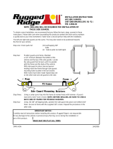
3. An auxillary attachment system (safety chain) is
required to retain the connection between towing
and towed machines in the event of separation of
the primary attachment system. The safety chain
should be routed through the tube on the hitch
and fastened to the tactor. A clevis or intermediate
chain support should be fastened to the tractor
drawbar no farther than 6” from the hitch pin. See
Fig. 1.
NOTE : The safety chain is not furnished with the
conveyor.
MOVING THE CONVEYOR
Move the conveyor with a tractor to or from the work
area. A pick-up truck or other suitable vehicle may be
used for transporting the conveyor over greater
distances. Comply with your state and local regulations
governing marking, towing and maximum width.
Observe safe driving and operation practices.
Follow these steps when transporting the conveyor:
1. Always transport your conveyor in the full-down
position.
2. There should be slight tension of the undercarriage
winch cable.
3. Hitch should be secured to tractor. Hitch safety
chain must be fastened in place.
1. The hitch jack is intended to lift the intake for
hitching and unhitching purposes. The jack should
be positioned approximately vertical to the
ground. Crank the jack handle clockwise to
extend the jack. Raise the intake only as much
as necessary to attach to the drawbar of the
towing vehicle.
FIG. 1
INTERMEDIATE
SAFETY CHAIN
SUPPORT
SAFETY CHAIN
(Not furnished with conveyor)
(Looped through anchor on hitch tube.)
HITCH TUBE
HITCH JACK
(Completely retract or
remove for transport)
5/09

Before moving the conveyor, the operator should
make sure all personnel are clear of the Moving
Conveyor Hazard Area as shown in the following
diagram. Never allow persons to stand underneath
or ride on the conveyor when it is being transported.
0400983A 03351A1 03654A1 1033638-6
Moving your portable conveyor requires careful
planning. Know the transport height of the conveyor
before moving it. Plan your route to avoid overhead
obstructions and power lines.
TRANSPORTING
DANGER: Be alert to overhead
obstructions and electrical wires.
Failure to do so may result in
electrocution. Lower conveyor
well below level of power lines
before moving. Maintain at least ten (10)
feet of clearance. See above chart showing
the height of each portable conveyor in the
transport position to determine the height
of your conveyor.
HAZARD AREA - KEEP OUT
MOVING THE CONVEYOR
IMPORTANT: Overall transport height is with the
conveyor fully lowered and attached to a towing
vehicle with a drawbar height of 16”.
Page 6
5/09

PLACEMENT OF CONVEYOR
GENERAL DIMENSIONS
1033638-7
TRANSPORTING
0400992A
AT MINIMUM INCLINE
AT MAXIMUM INCLINE
TRANSPORT POSITION
Page 7
5/09

Page 8
Step 1
Move conveyor slowly toward working position with a
tractor. Locate the conveyor on level ground as close
as possible to the bin or other structure. Leave
adequate room for loaded vehicles to reach the
conveyor intake area conveniently.The wheels must
be allowed to roll freely when raising. Be sure the
area is clear of any obstructions.
Step 2
0400984 1033638-8
TRANSPORTING
Raise the conveyor only high enough to allow minimum
clearance above the bin.
To raise the conveyor, turn the winch handle clockwise
(pulling) cable onto winch drum). There should be a
clicking sound. Observe the cable as it is winding onto
the winch drum. The cable should roll up on the drum
evenly; avoid cable build-up on one side of the drum.
NOTE: The winch is equipped with a brake that is
actuated by turning the handle. The brake is designed
to hold the load whenever the handle is released.
NOTE: For additional winch instructions, see page 21.
Make certain everyone is clear of
the work area when moving the
conveyor. To prevent tip-over when
backing, avoid rolling over any
obstructions. Also avoid moving the conveyor
at right angles to a slope. If the conveyor
must set on a slope, approach the bin uphill.
Make sure entire area above conveyor and
in line of travel is clear of overhead
obstructions and electrical wires. Failure to
do so may result in electrocution. Maintain
at least ten (10) feet of clearance.
Electrocution can occur without direct contact.
PLACEMENT OF CONVEYOR
Step 3
Back conveyor slowly into working position with a
tractor. DO NOT ATTEMPT TO INCREASE
CONVEYOR HEIGHT BY POSITIONING HEELS ON
LUMBER, BLOCKS OR BY OTHER MEANS.
1. Lower the conveyor until the conveyor discharge is
directly over the bin opening. Consider that the
discharge end will lower a few inches as the conveyor
fills with grain. NOTE: When discharging into a grain
spreader, maintain at least 12” of space between the
conveyor discharge and the spreader.
To lower the conveyor, turn the winch handle counter-
clockwise; there will be no clicking sound. To stop
while lowering the conveyor, turn the handle clockwise
until you hear two clicks to lock brake. (About a 6”
movement of the handle.)
2. Once the conveyor is in place, put the tractor in park.
3. Follow unhitching instructions in next section.
4. If desired, remove pins from hitch mount tube and
remove hitch from hitch mount.
5. Anchor the conveyor at the intake end and/or support
it at the discharge end to prevent tipping from
occurring when weight transfers to the top end as
the conveyor empties. It is a good practice to tie the
discharge end of the conveyor to the bin or storage
structure to prevent possible wind damage.
Remember to untie the conveyor before
attempting to move it.
Keep hands away from winch drum
during operation.
Don’t allow conveyor to become
hung up.
STEP 1
Locate conveyor next to bin.
STEP 2
Raise auger.
STEP 3
Back into position.
5/09

Page 9
0400044 1033638-9
UN-HITCHING
Follow these steps to unhitch the conveyor:
NOTE: When the tractor is to be disconnected from a
conveyor in the raised position, anchor the discharge
end of the conveyor to the bin or structure to prevent
possible wind damage.
A. The conveyor wheels should be chocked to prevent
the conveyor from rolling.
B. Remove safety chain and hitch pin. Disconnect
the tractor from the conveyor.
C. Lower discharge to bin.
Under no circumstances should
persons not involved in the
operation be allowed to trespass
into the work area.
It shall be the duty of all operators to see
that children and/or other persons stay out
of the work areas! Trespass into the work
area by anyone not involved in the actual
operation, or trespass into a hazard area
by anyone, shall result in an immediate
shut down by the operator.
It shall be the responsibility of all
operators to see that the work area has
secure footing, is clean and free of all
debris, and tools which might cause
accidental tripping and/or falling. It shall
also be their responsibility to keep the
work area clean and orderly during the
operation.
RULES FOR SAFE WORK AREA
Before starting the conveyor, a designated work area
should be established and properly marked. The
folllowing diagrams will show the manufacturers
designed work area. These areas shall be marked off
with colored nylon or plastic rope hung as portable
barriers to define the designated work areas.
ESTABLISH WORK AREA
Conveyor
Intake Area
Hazard
KEEP OUT
Wheel
Chocks
Under Conveyor
and Undercarriage
Area -
Hazard
KEEP OUT
WORK AREA
Authorized
Personnel Only
Support
Discharge
End
Overhead Wires
KEEP AWAY
DESIGNATED WORK AREA
5/09

Page 10
0400064A 1033638-10
It is essential to inspect your drive before adding
power and know how to shut down in an
emergency.
During the operation of your conveyor, one person shall
be in a position to monitor the operation. Any
conveyor when it is new or after it sets idle for a season
should go through a "break-in" period. The conveyor
should be run at partial capacity until several hundred
bushels of grain have been conveyed to polish the
inside of the tube. When the tube is polished, the
conveyor can be run at full capacity.
CONVEYOR BELT
INFORMATION
It is very important that the conveyor belt run in the
center of the conveyor when operating. Carefully read
through the belt tension and training instructions on
pages 40, 41 & 42 before attempting to operate the
conveyor.
ELECTRIC MOTOR DRIVE
INFORMATION
Always use a motor with required H.P. suggested in
the chart below. Use a motor that operates at 1750
RPM. Electric motors and controls shall be installed
by a qualified electrician and must meet the standards
set by the National Electrical Code and all local and
state codes. Reset and Motor Starting Controls may
be mounted directly to the conveyor or in a nearby
area, but they must be located so that the operators
have full view of the entire operation from the control
location.
A magnetic starter should be used to protect your
motor when starting and stopping. It should stop the
motor in case of power interruption, conductor fault,
low voltage, circuit interruption, or motor overload. Then
the motor must be restarted manually. Some motors
have built-in thermal overload protection. If this type
motor is used, use only those with manual reset.
Disconnect power before
resetting motor overloads.
Make certain electric motors are
grounded.
Electric motor is not provided. The motor sheave is
provided for 60 Hz, 1750 RPM drive after 10/31/08.
(No sheave is provided for 50 Hz drive.) Use the
following table for recommended sizes. Using these
recommendations will provide a belt speed of
approximately 645 FPM. NOTE: Standard driven
sheave provided is 15" pitch diameter.
RULES FOR SAFE WORK AREA
OPERATING PROCEDURES
06/10
RECOMMENDED MOTOR RECOMMENDED RECOMMENDED
ELECTRIC H.P. FRAME SIZE MOTOR PULLEY MOTOR PULLEY
FOR 60 Hz, 1750 RPM FOR 50 Hz, 1450 RPM
15 HP 254T Pitch Dia. 4.8"
3-Groove "B" Section Pitch Dia. 5.6"
3-Groove "B" Section
SHUT OFF POWER AND LOCKOUT
DRIVE TO ADJUST, SERVICE OR
CLEAN.
During the initial start up and
break-in period, the operator shall
be aware of any unusual vibrations
or noises, that would indicate a
need for service or repair.
Keep all safety shields and devices in place.
Keep hands, feet and clothing away from
moving parts.
The operator should have a full view of the
work area and check that all personnel are
clear of designated work area before adding
power.

Page 11
OPERATING PROCEDURES
1033638-11
SHUTDOWN
A. NORMAL SHUTDOWN
Make certain that the conveyor is empty before
stopping the unit. Before the operator leaves the
work area, the power source shall be locked out.
(See LOCKOUT).
B. INTERMITTENT OPERATION SHUTDOWN
When an conveyor is stopped and restarted under
full load, it may result in damage to the conveyor.
Therefore, if intermittent operation is to be carried
out, it is advisable to reduce the load level. When
kept from absolute filling, conveyor start-up is easier
and operation is more efficient.
C. EMERGENCY SHUTDOWN
Should the conveyor be immediately shut down
under load, disconnect and lockout the power
source. Clear as much grain from hopper and
conveyor as you can. Never attempt to start when
full. When as much grain as possible has been
cleared, reconnect power source and clear conveyor
gradually.
NOTE: Starting the unit under load may result in
damage to the conveyor. Such damage is
considered abuse of the equipment.
LOCKOUT
ELECTRIC DRIVE: A main power disconnect switch
capable of being locked only in the OFF position shall
be provided.
WARNING: If the operator must
leave the work area, or whenever
servicing or adjusting, the
conveyor must be stopped and the
power source turned off.
Precaution should be made to prevent
anyone from operating the conveyor when
the operator is absent from the work area.

Page 12 OPERATING PROCEDURES
RELOCATION OF CONVEYOR
0400985 1033638-12
OPERATING CAPACITIES
Capacities of belt conveyors can vary greatly under
diverse conditions. Different materials, moisture
content, amounts of foreign matter, angle of operation,
methods of feeding and speed all play a role in
performance of the conveyor. Capacities will be the
highest at lower angles of conveyor incline. For
instance, an expected capacity of 4000 to 5000 BPH
at a 15 degree conveyor incline may drop to less than
3000 BPH when the conveyor is at a 25 degree incline.
Maximum possible capacity will be less with high
moisture grain (above 15%) than with dry grain.
Feeding the material onto the feeder conveyor so that
it is moving in the direction of the belt travel will aid
capacity.
When grain conveying operation is completed, the
conveyor should be moved away from the bin and
lowered. The conveyor can then be moved to a different
bin for more conveying operations or cleaned up and
stored.
STEP 1
A. Empty all grain from the conveyor. Clean up the
area.
B. Untie any anchors and/or remove all supports.
C. Disconnect the power source.
Electric Drive - Unplug electric motor, wind up
electric cables.
D. Raise the conveyor so the discharge spout is clear
of bin opening. (See Step 2, Conveyor Raising
Instructions on page 8).
E. If removed, re-install the hitch tube assembly in
hitch mount on conveyor inlet.
C. Hitch the conveyor to the tractor. (See Hitching
Instructions on page 5.)
D. Remove wheel chocks.
E. Move conveyor slowly away from the bin with the
tractor.
STEP 2
A. Lower conveyor immediately after clear of bin or
storage structure.
IMPORTANT: Lower the conveyor, even if
relocating to a bin in the immediate area.
STEP 3
A. Follow unhitching instructions on page 9.
B. Inspect the conveyor as outlined in “Machine
Inspection” on page 3.
RELOCATION OF CONVEYOR
STEP 2
Lower conveyor
STEP 3
Move to next bin or unhitch
STEP 1
Move away from bin

Page 13
01046A1 1033638-13
GENERAL
For economical and efficient operation of your conveyor,
maintain regular and correct lubrication. Neglect leads
to reduced efficiency, excessive wear and needless
down time. Use the schedule on page 14.
Any parts needing replacement should be replaced
with parts of the same type and size. Do not modify
or alter any of the conveyor components.
All bearings are fitted with grease zerks and should be
lubricated as specified in the maintenance schedule
on page 14. Before greasing the bearings, make
certain the zerks are free of dirt, otherwise this will be
passed into the bearing race. NOTE: Overgreasing
can be as harmful as under greasing, if it forces grease
out of the bearing seals.
PULLEY & “S” ROLLER
BEARINGS
LUBRICATION & MAINTENANCE
Keep all safety shields and devices
in place. Replace any that are
damaged or missing.
Shut off power and lockout drive to
adjust, service or clean.
DUST
CAP
SLOTTED
NUT
OUTER
BEARING
INNER
BEARING
COTTER
KEY
SEAL
HUB
Undercarriage Axle Spindle Bearing
Tapered roller type bearings are standard on the seed
belt conveyor and should be repacked with grease
and adjusted annually or as needed, determined by
usage.
Care must be used in dismantling wheel bearing
assemblies. First remove the dust cap by prying
around the edges. Remove the cotter pin, slotted
nut and flat washer. Carefully remove the hub and
bearings from the spindle. Inspect all parts for wear
or damage and replace with new ones, if necessary.
When reassembling the hub, repack both bearing
cones with grease and fill the hub cavity 1/3 full. Place
inner bearing assemblies into the hub, and then press
seal into hub and carefully reinstall the hub on the
spindle. When placing hub on spindle be careful not
to damage the lip of the grease seal. Install outer
bearing assembly into the hub, and replace flat
washer and slotted nut. Then tighten the slotted nut
to seal the bearings until the hub binds as you rotate
hub. Back off the slotted nut to the next slot and
install a new 5/32" x 1 1/4" long cotter pin. Replace
dust cap.
WHEEL BEARINGS
DRIVE BELT ADJUSTMENT
On drives that are powered by belts, the belt tension
will need periodic adjustment. Use the adjustment
bolt under the motor mount plate.
06/10

Page 14
1033638 -14
LUBRICATION & MAINTENANCE
MANUAL WINCH
Check the winch handle assembly on your conveyor
to determine that it has been assembled correctly.
See assembly section.
SAFETY REMINDERS
1. Operator must pay attention during raising and
lowering.
• Watch cable to see if it is coiling properly
onto winch drum evenly.
• Keep hands away from winch drum during
operation.
• Don’t use hands to guide cable onto winch
drum during winch operation.
• Don’t continue to raise side panels after they
reach the stops.
The following lubrication checks should be made to
the winch periodically.
The conveyor hopper side panels should be in the
lowered position when this inspection is being
performed. Refer to operating and maintenance
instructions furnished with your winch for proper
inspection methods.
1. All gears should have a film of grease on them at
all times.
2. Check brake disc. If worn to less than 1/16" thick,
cracked or broken, replace both discs.
3. The following parts must be wet with oil at all
times:
A. Two bushings located at ends of drum shaft.
B. The ratchet pawl pivot.
IMPORTANT: Do not get oil or grease on brake
disc faces (located between ratchet gear brake
hub and pinion shaft.)
Never fully extend the cable and always
keep three complete turns of cable around
winch drum. Never operate winch with wet
or oily hands and always use a firm grip
on the handle.
CONVEYOR MAINTENANCE
SCHEDULE
° Inspect and replace the belt splice every 800,000
bushels or 265 hours.
° Back the tension adjustment bolts all the way off for
the belt during the off season.
° Insert one - two pumps of grease in each of the
bearings every 500,000 bushels or 165 hours or once
a season, whichever is reached first (too much grease
can push out the bearing seals) and after each time
the unit is washed down. After the wash down, insert
just enough grease to push out the water and let run
for 15 minutes.
° Check all the drive belts on the unit and adjust, as
needed.
° Examine all of the skirting at least every 1,000,000
bushels or 335 hours and replace, as needed.
° Check each bearing and return roller every 750,000
bushels or 250 hours or once a season, whichever is
reached first.
° Clean all material out of the inlet hopper and main
tube. Make sure to check under all of the skirting.
° If the unit will set outside during the off season, make
sure that the discharge hood is installed and cover
the inlet hopper section with a tarp or plastic. Keep
the tarp or plastic off the ground. This should help
keep rodents out of the unit and protect the belts.
Store the unit inside out of the weather, if possible.
Sunlight is hard on the belt and hoses.
° Keep the inlet section off the ground. This will also
help keep rodents out of the unit and protect the
belts. (Rodents can destroy a coslty belt during
long idle periods.)
° Before start up, tighten the tension adjustment bolts
on the belt and check for proper alignment on start
up.
° Check belt alignment during each operational
season, adjust as needed.

Page 15
1033638-15
ASSEMBLY INSTRUCTIONS
NOTE: Whenever reference is made to right or left side
of conveyor, it is determined by standing at the inlet
end of the conveyor and looking toward the discharge
end.
1. Set the flanged tube weldments (Item 5 & 6) on saw
horses. The bottom of the 10" conveyor tube should
be at least 30" off the floor or assembly surface.
Add spacer material on top of saw horses to get
this height, if necessary. Bolt the lower and upper
tube flanges together with eight 3/8” x 1” long bolts
and locknuts.
IMPORTANT: The weld seam of the tubes should
be on top of the conveyor. Arrange tube so caution
decals are nearest the bottom or inlet end of the
conveyor and logo decals are nearest the top or
discharge end of the conveyor.
2. Position the inlet assembly (Item 1) near bottom or
inlet end of conveyor tube assembly. Place saw
horse and appropriate spacers under the inlet
assembly, so that it is supported at a height which
aligns with the conveyor tube assembly. Loosely
connect the inlet assembly flange to the tube flange
with eight 3/8" x 1" bolts and 3/8" locknuts. Using
three of the top flange bolts, mount the pull
handle mount bracket. Refer to drawings on
pages 25 and P-3 (Item 18). Level the inlet assembly
from side to side using a carpenter’s level placed
across the inlet frame perpendicular to the conveyor
tube. Tighten bolts once inlet assembly is level.
IMPORTANT: Throughout the remainder of the tube
assembly, each part installed will be leveled to
assure that all rotating components (such as pulleys
and return rollers) remain in alignment with each
other. This is not only critical for part alignment,
but also will improve the performance of the belt
when placed in operation.
3. Insert cable pull handle through the pivot holes of
the handle mount bracket just installed and secure
with a 5/32” x 1-1/4” cotter pin. NOTE: The handle
can go through the mount either way, depending on
if right or left hand operation is desired.
HEAD, INLET AND CONVEYOR
TUBES
NOTE: The take-up adjusting bolts should be
pointing toward the discharge end of the conveyor.
Loosely clamp the drive assembly to the lower
tube using the motor mount support weldment
(Item 12) and one 10” x 4” wide half band (Item 11)
and twelve 3/8” x 1-1/4” long bolts and locknuts.
On PTO Models, use two 10” x 4” halfbands in
place of the motor mount support. Level the drive
from side to side using a level placed across the
drive frame. Tighten bolts once drive is level.
6. Position the undercarriage track housing weldment
(Item 4) on the lower tube (Item 5). Locate the
track housing 17’-7 3/8” up from the flange
connection at the inlet end of the lower tube.
NOTE: The track housing is made symmetrical,
so it does not matter which end points toward the
discharge end of the conveyor. Loosely clamp
the track housing to the lower tube with a 10” x 4”
wide half band (Item 11) at each end and a 10” x
4” wide truss mount band (Item 10) in the center.
Again, use twelve 3/8” x 1-1/4” long bolts and
locknuts. Level the housing side to side. Tighten
bolts once track housing is level.
7. Position the radius arm mount band (Item 15) on
the lower tube (Item 5). Locate 5’-5” up from
the flange connection at the inlet end of the
lower tube. Loosely clamp to the tube, using a
10” x 6” wide truss mount band (Item 16) and six
3/8” x 1-1/4” long bolts and locknuts. Level side
to side and tighten bolts.
8. Establish the locations of the return roll supports
(Items 7, Part No. 1026885 & 9, Part No. 1025616).
There are two locations. The distance is
4’-9” & 33’-2 7/8”. Distance is from flange
connection at inlet end of tube assembly to edge
of return roll support bands. Loosely clamp the
return roll supports to the conveyor tube at these
locations. Use one 4” wide half band (Item 11)
and four 3/8” x 1-1/4” long bolts and 3/8” locknuts
to mount each support. One side of each roll
support has an adjustment bracket attached. It
will work best if the supports are positioned so
that all the brackets are on the left side of the
conveyor looking from inlet toward discharge.
Level the return roll supports from side to side
using a level placed across the bottom of the
support perpendicular to the conveyor tube.
Tighten bolts once return roll support is level.
4. Position the discharge assembly (Item 2) near the
top or discharge end of conveyor tube assembly.
Place saw horse and appropriate spacers under
the discharge assembly, so that it is supported at
a height which aligns with the conveyor tube
assembly. Loosely connect the discharge assembly
flange to the tube flange with eight 3/8" x 1" bolts
and 3/8" locknuts. Level the discharge assembly
from side to side using a carpenter’s level placed
across the discharge frame perpendicular to the
conveyor tube. Tighten bolts once discharge
assembly is level.
9. Install return rollers (Items 8) into hex holes of
return roll supports (Item 7 & 9). Insert the non-
spring loaded hex shaft end of the roller first, then
depress the spring loaded hex shaft end and slide
into place until shaft pops through the hex hole of
the roller support weldment.
12/11
5. Position the drive assembly (Item 3) on the lower
tube (Item 5). Locate the drive 9’-6 1/4” up
from the flange connection at the inlet end of
the lower tube.

Page 16 ASSEMBLY INSTRUCTIONS
Ref. No. Part No. Description
1 1032297 Inlet Assembly
2 1023772 Discharge Assembly
3 1033582 Drive Assembly
4 1032848 Undercarriage Track Housing Weldment
5 1032970 Lower Conveyor Tube
6 1032971-220 Upper Conveyor Tube (Hutch)
6 1032971-320 Upper Conveyor Tube (Mayrath)
7 1026885 Return Roll Support
8 1023329 Return Roller w/Hex Shaft
9 1025616 Return Roll Support
10 1033006 Truss Mount Band
11 5930A1 Half Band 10” x 4” wide
12 1023722 Motor Mount Support (Electric Model Only)
13 1026984 Guide Roller Support
14 1026098 Guide Roller Assembly
15 1023454 Raduis Arm Pivot Mount
16 1007807 Truss Mount Band
17 1033107 Truss Cable Anchor Band
18 1025602 Return Roll Adjusting Bracket
19 106207-1 Half Band 10” x 6” wide (PTO Model Only)
20 1035831 Lower Gearbox Support (PTO Model Only)
0400978A1 1033638-16
HEAD, INLET AND CONVEYOR
TUBES - CONT. 11.Install a return roller (Item 8) into hex holes in the
adjusting brackets and those in the track housing
(Item 4) side panel. Refer to step 8 for procedure.
10. Bolt a return roller adjusting bracket (Item 18) to
each end of the track housing (Item 4), using 1/4”
x 3/4” long carriage bolts, flat washers, lock
washers and nuts. One bracket will be on the
right hand side of the conveyor and one will be on
the left hand side.
7/09

ASSEMBLY INSTRUCTIONS Page 17
1033638-17
CONVEYOR TRUSS
NOTE: Whenever reference is made to right or left
side of conveyor, it is determined by standing at the
inlet end of the conveyor and looking toward the
discharge end.
1. Attach the truss side bars (Item 5) to the truss
mount band (Item 3) with four 1/2” x 1 1-2” long
bolts and 1/2” locknuts. NOTE: The mount band
was installed on the conveyor tube earlier during
the tube assembly.
2. Install the truss crossbrace (Item 6) between the
two truss side bars just installed. Use two 3/8” x
1-1/4” long bolts and 3/8” locknuts.
3. Attach truss side bars (Items 5) to the truss mount
band (Item 4) located at the center of the track
housing weldment. Use four 1/2” x 1-1/2
long bolts and locknuts.
4. Install the truss crossbrace (Item 6) between the
two truss side bars just installed, using two 3/8” x
1-1/4” long bolts and locknuts.
5. Loosely attach a 3/8” cable clamp (Item 11) to the
top ends of the upper side bars (Item 5).
6. Install the eyebolts (Item 7) to the truss anchor
tabs on the sides of the discharge housing
(Item 2). The eye end of each eyebolt should be
pointing toward the inlet end of the conveyor. Install
two 5/8” non-lock nuts on each eyebolt.
7. Wrap one end of each truss cable (Items 10) around
the cable anchor loops on the truss cable anchor
band at the inlet end of the conveyor tube. Secure
cable clamps (two per end) (Item 9), so that the
bolt of the clamp is against the loose end of the
cable.
8. Run the 1/4” x 44’ long truss cables through the
cable clamps (Item 11) at the top ends of the truss
side bars (Item 5), then towards the discharge end
of the conveyor.
9. Attach truss cables to eyebolts (Item 7) using two
cable clamps (Item 9) per each cable. Secure the
clamp u-bolts against the loose end of the cable.
10.Using the eyebolts (Item 7) tighten the cables until
they are reasonably snug. Tighten cables equally.
DO NOT OVERTIGHTEN. Sight down the tube to
make sure it is straight. Some adjustment can be
made after the conveyor is completely set-up.
However, the wind guard bolts may have to be
loosened to pull the conveyor tube up.
11.Tighten cable clamps (Item 11) that secure cables
to truss side bars (Item 5).
12.Clamp the guide roller support (Item 13) to the 10”
diameter tube of the intlet housing using a 10” x 4”
wide truss cable anchor halfband (Item 17) and four
3/8” x 1-1/4” bolts and hex nuts. Locate 9-7/8”
down from tube flange connections.
(See drawing below.)
13. Fasten the guide roller assembly to the guide roller
support using four 3/8” x 1-1/4” bolts, flat washers
and locknuts.
14. Install a hex shaft roller into the hex holes of the
inlet housing.
15.On PTO drive models, position the lower gearbox
support (Item 20) on the lower tube (Item 5).
Locate 3’-2 3/8” up from the flange connection
of the tube. Use a 10” x 6” wide half band and six
3/8” x 1-1/4” long bolts and locknuts.
HEAD, INLET AND CONVEYOR
TUBES - CONT.
0400251B112/11

Page 18 ASSEMBLY INSTRUCTIONS
CONVEYOR TRUSS - CONT.
0400979 1033638-18
Ref. No. Part No. Description
1 Ref. Inlet Assembly
2 Ref. Discharge Assembly
3 Ref. Truss Mount Band (Item 15 of Tube Assy.)
4 Ref. Truss Mount Band (Item 10 of Tube Assy.)
5 106399 Truss Side Bar
6 106398 Truss Cross Bar
7 866015-1 Eyebolt 5/8” x 1”
8 D1170 Nut 5/8” Hex
9 6369C Cable Clamp 1/4”
10 1002573 Cable 1/4” x 44’ lg.
11 3010L1 Cable Clamp 3/8”
5/09
/