Page is loading ...

PRODUCT DATA
Copyright © 1998 Honeywell Inc. • All Rights Reserved
7800 SERIES
S7810A Data
ControlBus™ Module
APPLICATION
The S9810A Data ControlBus™ Module supports remote
mounting of a Keyboard Display Module, personal computer
communications interface, and remote reset.
The S7810A 7800 SERIES is programmed to provide a level
of safety, functional capability and features beyond the
capacity of conventional controls. Functions provided by the
7800 SERIES include automatic burner sequencing, flame
supervision, system status indication, system or self
diagnostics and troubleshooting.
SPECIFICATIONS
Electrical Ratings:
Voltage and Frequency: 13 Vdc peak full-wave rectified
(+20/-15%).
Power Dissipation: 2W maximum, 2 VA maximum.
Terminal Ratings:
Power: 13 Vdc peak full-wave rectified.
Earth ground.
ControlBus (1(a), 2(b), 3(c)) 5 Vdc at 1 mA maximum.
Electrical Connectors (included):
Part no. 203541 ControlBus 5-Wire Electrical Connector.
FEATURES
• Communications bus interface.
• Remote reset.
• Ability to remotely mount a Keyboard Display Module.
NOTE: Many jurisdictions restrict remote resetting of an
appliance and require a location with line-of-sight
viewing of the appliance. Install the S7810A Data
ControlBus™ Module in accordance with local
requirements.
65-0091-3
Environmental Ratings:
Ambient Temperature:
Operating: -40° F to 140° F (-40° C to 60° C).
Storage: -40° F to 150° F (-40° C to 66° C).
Humidity: 85% RH continuous, noncondensing.
Vibration: 0.5G environment.
Weight:
4 ounces (114 grams) unpacked.
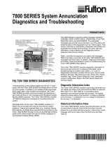
Dimensions:
Refer to Fig. 1.
M1986A
BURNER CONTROL
2-3/4
(69)
29/32
(23)
5/32
(4)
4-27/32
(123)
Fig. 1—Mounting dimensions of the S7810A
Data ControlBus Module™ in in. (mm).

7800 SERIES S7810A DATA ControlBus™ MODULE
65-0091—3 2
ORDERING INFORMATION
When purchasing replacement and modernization products from your TRADELINE® wholesaler or distributor, refer to the
TRADELINE® Catalog or price sheets for complete ordering number.
If you have additional questions, need further information, or would like to comment on our products or services, please write or
phone:
1. Your local Home and Building Control Sales Office (check white pages of your phone directory).
2. Home and Building Control Customer Logistics
Honeywell Inc., 1885 Douglas Drive North
Minneapolis, Minnesota 55422-4386 (612) 951-1000
In Canada—Honeywell Limited/Honeywell Limitée, 155 Gordon Baker Road, North York, Ontario M2H 3N7.
International Sales and Service Offices in all principal cities of the world. Manufacturing in Australia, Canada, Finland, France,
Germany, Japan, Mexico, Netherlands, Spain, Taiwan, United Kingdom, U.S.A.
INSTALLATION
When installing this product…
1. Read these instructions carefully. Failure to follow them
could damage the product or cause a hazardous
condition.
2. Check the ratings given in the instructions and marked
on the product to make sure the product is suitable for
the application.
3. The installer must be a trained, experienced Flame
Safeguard service technician.
4. Disconnect the power supply before beginning
installation to prevent electrical shock and equipment
damage. More than one power supply disconnect may
be involved.
5. Wiring must comply with all applicable codes,
ordinances and regulations.
6. After installation is complete, check out the product
operation as provided in these Instructions.
IMPORTANT
1. This equipment generates, uses and can radiate
radio frequency energy and, if not installed and used
in accordance with the Instructions, can cause
interference with radio communications. It has been
tested and found to comply with the limits for a
Class B computing device of Part 15 of FCC rules,
which are designed to provide reasonable protection
against such interference when operated in a
commercial environment. Operation of this
equipment in a residential area may cause
interference; in which case, users at their own
expense may be required to take whatever
measures are required to correct this interference.
2. This digital apparatus does not exceed the Class B
limits for radio noise for digital apparatus set out in
the Radio Interference Regulations of the Canadian
Department of Communications.
Humidity
Install the S7810 where the relative humidity never reaches
the saturation point. The S7810 is designed to operate in a
maximum 85 percent relative humidity or continuous,
noncondensing, moisture environment.
Vibration
Do not install the S7810 where it could be subjected to
vibration in excess of 0.5G continuous maximum vibration.
Weather
The S7810 is not designed to be weather tight. If installed
outdoors, the S7810 must be protected by an approved
weather-tight enclosure.
Mounting Data ControlBus™ Module
(See Fig. 2)
1. Align the two interlocking ears of the Data ControlBus™
Module with the two mating slots on the 7800 SERIES
Relay Module.
2. Push on the lower corners of the Data ControlBus™
Module with a hinge action to secure it to the 7800
SERIES Relay Module.
Fig. 2 —Data ControlBus™ Module Mounting.

7800 SERIES S7810A DATA ControlBus™ MODULE
65-0091—33
WIRING
1. Disconnect the power supply from the main disconnect
before beginning installation to prevent electrical shock
and equipment damage. More than one disconnect may
be involved.
2. All wiring must comply with applicable electrical codes,
ordinances and regulations.
3. Recommended wire size and type:
a. Use an unshielded no. 22 AWG, 2-wire twisted
cable with one wire for ground (for communications
purposes), if the leadwire run and noise
conditions permit. However, some installations
may need up to five wires; three for
communications and two for remote reset (in
either a single cable or separate cables) or
Belden 8771 shielded cable or equivalent. The
Data ControlBus™ Module (for remote mounting
or communications) must be wired in a daisy
chain configuration, 1(a)-1(a), 2(b)-2(b), 3(c)-3(c).
The order of interconnection of all the devices is
not important. Be aware that modules on the
closest and farthest end of the daisy chain
configuration string require a 120 ohm (1/4 watt
minimum) resistor termination across terminals 1
and 2 of the electrical connectors for any
connections over 100 feet, see Figs. 3 and 4.
b. Use no. 22 AWG wire insulated for voltages and
temperatures in applications that use the 13 Vdc
peak fullwave rectified power supply. Suggested
wire types include TW (60C), THW (75C) and
THHN (90C).
1
1
120 OHM
RESISTOR
1
120 OHM
RESISTOR
A
B
A
B
C (GND)
+13 VDC
RESET
C (GND)
+13 VDC
RESET
123 45
123 45
MOMENTARY
PUSHBUTTON
SWITCH
S7810 DATA CONTROLBUS™ MODULE
(MOUNTED ON 7800 SERIES RELAY MODULE)
S7800 REMOTE KEYBOARD DISPLAY MODULE
THREE-WIRE SHIELDED CABLE MAY BE REQUIRED. TWO 120
OHM TERMINATING RESISTORS ARE REQUIRED FOR
CONNECTIONS OVER 100 FEET. CABLE SHIELD MUST BE
TERMINATED TO EARTH GROUND AT BOTH ENDS. IF SHIELDED
CABLE IS NOT USED, TWISTED PAIR WIRE MUST BE USED.
WHEN CONNECTING THE KEYBOARD DISPLAY MODULE DATA
CONTROLBUS™ MODULE, OR REMOTE RESET MODULE
EXTERNAL FROM THE CONTROL CABINET, APPROPRIATE
MEASURES MUST BE TAKEN TO MEET EN60730 SAFETY
LOW VOLTAGE REQUIREMENTS (SEE APPROVALS). M1987C
2
2
Fig. 3. Wiring Data ControlBus™ Module.
4. Recommended grounding practice for Dat
ControlBus™ Module is to connect the shield, if used,
to signal ground, terminal 3(c), provided as a part of the
7800 SERIES device ControlBus connection, see Figs.
3 and 4. Connect the shield at both ends to earth
ground.
5. Recommended wire routing:
a. Do not route the Data ControlBus™ MODULE
cable in conduits with line voltage circuits.
b. Avoid routing the Data ControlBus™ Module
cable in the same conduit with or close to ignition
transformer leadwires.
c. Route the Data ControlBus™ Module cable
outside of conduit if it is properly supported and
protected from mechanical damage.
6. Maximum wire lengths:
a. Use 1000 feet maximum length of all
interconnecting wire for Data ControlBus™
Module and Keyboard Display Module leadwires.
b. Use 1000 feet maximum length of wire to a
Remote Reset Switch for Remote Reset leadwires.
7. Install all electrical connectors.
8. Restore power to the panel.
1
MOMENTARY
PUSH BUTTON
SWITCH
A
2 3 4 5
B
C (GND)
+ 13 VDC
RESET
S7810 DATA CONTROLBUS MODULE™
(MOUNTED ON 7800 SERIES RELAY MODULE)
1
A
2 3
B
C
QS7800
COMMUNICATIONS INTERFACE
CONTROLBUS MODULE (LOCATED
AT THE Q7700 NETWORK
INTERFACE UNIT.)
120 OHM
RESISTOR
1
120 OHM
RESISTOR
1
1THREE-WIRE SHIELDED CABLE MAY BE REQUIRED. TWO 120
OHM TERMINATING RESISTORS ARE REQUIRED FOR
CONNECTIONS OVER 100 FEET. CABLE SHIELD MUST BE
TERMINATED TO EARTH GROUND AT BOTH ENDS. IF SHIELDED
CABLE IS NOT USED, TWISTED PAIR WIRE MUST BE USED.
M2673A
Fig. 4. QS7800 Wiring Data ControlBus™ Module to
Communications Interface ControlBus™ Module.
NOTE: Many jurisdictions restrict remote resetting of an
appliance and require a location that provides line-
of-sight viewing of the appliance. Install the S7810A
Data ControlBus™ Module in accordance with local
requirements.

7800 SERIES S7810A DATA ControlBus™ MODULE
65-0091—3 4
Honeywell Europe S.A.
3 Avenue du Bourget
1140 Brussels
Belgium
Honeywell Asia Pacific Inc.
Room 3213-3225
Sun Hung Kai Centre
No. 30 Harbour Road
Wanchai
Hong Kong
Home and Building Control
Honeywell Limited-Honeywell Limitée
155 Gordon Baker Road
North York, Ontario
M2H 3N7
Honeywell Latin American Region
480 Sawgrass Corporate Parkway
Suite 200
Sunrise FL 33325
65-0091—3 G.R. Rev. 11-98
Home and Building Control
Honeywell Inc.
Honeywell Plaza
P.O. Box 524
Minneapolis MN 55408-0524
Printed in U.S.A. on recycled
paper containing at least 10%
post-consumer paper fibers. www.honeywell.com
/