Page is loading ...

Instruction Manual
ST-30 Series
Copyright © 05/03
Motic Microscopes, European Division.

ST-30C-2LOO
-2-
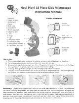
7. On switch
6. Incident illumination
5. Objectives
12. Head holder
support screw
18. Base
1. Eyepiece
10. Diopter
adjuster
13. Focus knob
16. Incident
illumination
switch (I)
17. Transmitted
illumination
switch (T)
4. Head
2. Eyepiece tube
8. Stage sample clips
15. Column
9. Stage
3. Prism Housing
14. Illuminator
support screw
11. Head holder

Introduction
Thank you for your purchase of a Motic microscope. Motic microscopes are precision instruments, subjected
to meticulous examination to reach you in perfect condition. Their design combines easy management and
optimum functioning with minimum maintenance.
The information contained in this manual is likely to go beyond what the average user needs to know to use
the stereomicroscope, however, it is provided to answer any queries that may arise.
Stereomicroscopes are used to study three dimensional objects, examine small parts, or dissect biological
specimens. They also permit the observation of slide specimens.
These instructions should be read carefully before operating the microscope. They will permit you to use
your new stereomicroscope to its fullest capabilities. Terminology used to describe components and controls
can be found in the diagram on page 2.
These instructions are based on the assembly and use of the ST-30C-2LOO model, with additional notes
applying specifically for the other models in the series. For those models with A objectives, objectives
referred to are 1X and 2X (rather than 2X and 4X); whilst for models with B or objectives referred to are 1X
and 3X.
Unpacking
All components of the stereomicroscope have been carefully packed to ensure they reach you in perfect
condition. We recommend that you do not discard any packing containers in case you need to return the
microscope, store it for long periods of time; or should it become necessary to transport it to a technical
service for any repair, or maintenance procedure.
The box should contain the following components:
• All the ST-30/36/37 models: A base with incident illumination, a binocular head with mounted
eyepieces, a black and white plastic stage, a frosted glass stage, eyepiece protectors, a protective
cover and a 2mm hexagonal key.
Remove and handle all components of the microscope with extreme care.
Avoid touching the lenses of the optical elements and keep clear of contact with dust, water or other
contaminating agents, as they could stain, or damage the lens surface and affect the quality of the
image.
Description of Components
1. Head (4). Available in binocular or trinocular and rotating 360º, according to the model.
2. Eyepiece (1). The group of lenses closest to the eye, magnifying the image formed by the objectives.
3. Diopter adjustment (10). Permits the user to adjust the focus for different levels of vision.
4. Objectives Turret (5). The revolving action permits the user to change the degree of magnification,
the correct positioning of the objectives is marked by a “click” in the optical path.
5. Objectives (5). The group of lenses closest to the sample, or microscopic specimen forming the first
magnified image.
6. Stage (9). Platform where the specimen is placed. With holder clips.
7. Focusing Knobs (13). Situated on both sides of the arm of the stereomicroscope, they allow the
object to be brought into focus.
8. Illumination (6). Depending on the model, 12V y 10W incident illuminated (Base LO) or incident and
transmitted illumination (Base 2LOO).
-3-

Assembly
All the steps described for the assembly of the stereomicroscope must be undertaken with extreme
care, and without forcing the placement of the distinct parts and elements of the microscope.
A. Place the stereomicroscope, on a flat, stable and clean
surface.
B. For models ST-36/37.
For greater comfort place the head (4) with the
eyepiece (1) to face the opposite direction from the
arm and column (14).
1. Loosen the head holder support screw (Fig. 1)
and turn the head 180º.
2. Tighten the head holder support screw.
Warning: Before connecting the microscope to an electrical source, always check that
the voltage coincides with that of the stereomicroscope.
Operation
A. Starting Up.
The stereomicroscope comes with two stage plates. One is frosted for the observation of
microscopic specimens slides, or thin, or transparent samples such as leaves or insect wings. The
black and white stage plate is used to study opaque objects, or for dissection. The best contrast of a
sample would depend on the colour of the stage plate chosen.
1. Changing the stage.
a. Loosen the locking set screw (Fig. 2) with the key
provided, and remove stage (9).
b. If glass stage is used, place it with the frosted surface
facing down.
c. Tighten locking set screw
Depending on the stereomicroscope, there are three types of light switch on the base.
MAIN : Turns the entire unit on or off.
I : Turns incident light on or off. (Top illumination)
T : Turns transmitted light on or off. (Bottom illumination)
2. Press the main switch to position “I” (7).
3. Press the incident or transmitted illumination switch (16-17), or both at once, to position “I” or “II”,
according to necessities in examining the sample.
-4-
Head
holder
support
screw
Fig. 1
Fig. 2
Locking set
screw

B. Interpupillary Adjustment.
1. Whilst looking through both eyepieces (1), move eyepiece tubes (2) on their axis, holding head
by the eyepiece tubes housing the prisms. (3).
2. When a full field of view is obtained, and converted into a single image, interpupillary distance is
correct for your eyes.
3. Each user must adjust interpupillary distance to match their eyesight
C. Focussing
1. Turn objective turret (5) so that the lowest magnification number 2X is facing the front of the
microscope, lined up with the eyepiece, and the 4X magnification is located at the two sides,
perpendicular to the eyepiece. The turret permits a 1/4 turn. Make sure that turret is “clicked”
into its correct position.
NB: Fot ST-37 model, omit steps 2,3 and 4, passing directly to 5.
2. Place a flat object or a slide on center of stage (9).
3. Turn focus knobs (13) to mid range.
4. The head holder (11) is mounted on a column (15), and can be moved up or down to
accommodate the size of the sample.
a. Support head (4) with one hand without touching any lens.
b. Without letting go of the head, loosen the screw supporting the head holder (12).
c. While looking through the eyepiece (1), move the head holder up or down until the object
appears in focus.
d. Tighten the head holder support screw.
e. These steps are not necessary every time the stereomicroscope is used, only when the sample
is not in the range of focus.
5. Turn focus knobs (13) until the image is sharp.
D. Adjusting the diopter.
On the left eyepiece tube there is a diopter adjustment collar. Its normal position is when the lower
part of the collar is aligned with the sign marked on the eyepiece tube.
In the case of differences in eyesight:
With the right eye, look through the right eyepiece (1) and adjust focus.
Now use the left eye to look through the left eyepiece, and adjust the focus by turning the diopter
adjuster, on the left hand eyepiece tube, until a detailed image is achieved. Do not adjust the focus
with the focus knobs (13).
E. Changing magnification.
Turn objective turret (5) so that the highest magnification number 4X is facing the front of the
microscope, lined up with the eyepiece, and the 2X magnification at the two sides, perpendicular with
the eyepiece. The turret permits a 1/4 turn. Make sure that turret is correctly “clicked” into correct
position.
-5-

1. Although this stereomicroscope comes parafocalled, the focus has to be adjusted owing to the
greater depth of field offered by those objectives of lower magnification. Depth of field is the
capacity to focus on distinct points, on distinct levels.
2. Once the image with objectives of higher magnification is brought into focus, it is not necessary
to re-focus with those of a lower magnification level.
Specification chart:
Eyepieces
Objectives
WF5x
(optional)
WF10x
WF15x
(optional)
WF20x
(optional)
Working distance
Total
magnifica
tion
Field size
Total
magnifica
tion
Field size
Total
magnifica
tion
Field size
Total
magnifica
tion
Field size
Binocular Trinocular
A
1x 5x 22 mm 10x 20 mm 15x 13 mm 20x 9,5 mm
95 mm 95 mm
2x 10x 11 mm 20x 10 mm 30x 6,5 mm 40x 4,8 mm
B
1x 5x 22 mm 10x 20 mm 15x 13 mm 20x 9,5 mm
94 mm 80 mm
3x 15x 7,3 mm 30x 6,7 mm 45x 4,3 mm 60x 4,3 mm
C
2x 10x 11 mm 20x 10 mm 30x 6,5 mm 40x 4,8 mm
94 mm 80 mm
4x 20x 5,5 mm 40x 5 mm 60x 3,3 mm 80x 3,3 mm
Maintenance
WARNING: FOR YOUR OWN SAFETY SWITCH OFF AND DISCONNECT THE MICROSCOPE FROM
ANY ELECTRICAL SOURCE BEFORE ATTEMPTING ANY MAINTENANCE PROCEDURE TO AVOID THE
RISK OF ELECTROCUTION.
CONSULT YOUR DISTRIBUTOR IF ANY REPAIR, OR MAINTENANCE PROCEDURE IS REQUIRED TO
YOUR MICROSCOPE THAT DOES NOT APPEAR IN THIS INSTRUCTION MANUAL.
A. Optical maintenance.
Do not attempt to disassemble any optical component. For any repair work not specified in this manual,
consult the technical service responsible in your area.
Before cleaning the lens surface, remove dust with a brush specifically for lenses, or with low pressure
compressed air, found in any photography shop.
1. Cleaning the eyepiece.
a. Do not remove the eyepiece (1) from the eyepiece tube (3).
b. Clean the external surface, dampening the lens with breath.
c. Afterwards, dry the lens with special lens paper. Dry in circular movements from the centre o
the lens, outwards. Do not wipe the lens when already dry, as they scratch easily.
2. Cleaning the objectives.
a. Do not remove objectives from the microscope.
b. Only clean the surface area. Use a soft cotton cloth dampened slightly with Xylene. Dry the
lens afterwards with the same cloth.
-7-

B. Electrical Maintenance
1. Changing the transmitted illumination bulb.
a. Loosen the stage fixing screw (Fig. 2) with the key provided, and remove the stage (9).
b. Remove the bulb carefully, pulling it straight out of the socket.
c. Place the replacement bulb in the socket.
d. If the bulb has been touched with the hands it should be immediately cleaned as this could
affect light transmission, and the duration of the bulb.
e. Replace the stage and tighten the screw.
2. Changing incident illumination bulb.
a. Unscrew the illuminator protector tube (14), turning it anti-clockwise, and removing the tube
from that of the lenses.
b. With a cloth carefully pull out the bulb to disconnect it from the socket.
c. Insert replacement bulb in socket.
d. If the bulb has been touched with the hands, clean it as this could affect light transmission, or
the duration of the bulb.
e. Replace the bulb cover and tighten the screw.
• For LED models.
a. Unscrew the bulb protector tube, turning it anti-clockwise. Be carerully with the protection
glass.
b. Pull down the LED panel and disconnect the plug.
c. Connect the plug of the replacement LED panel.
d. Replace the bulb protector tube, turning it in a clockwise direction.
3. Changing the fuse.
a. With a flat screwdriver, press lightly on the slot of the
fuse cap (Fig.5) and turn 1/4 turn as indicated by the
arrow.
b. Release pressure and the fuse cap should be loose.
Extract it completely.
c. Remove the fuse in the cap, and insert the new one.
Make sure that it is 0.5 Amps.
d. Replace the cap with the fuse.
e. Repeat step (a.) but turn 1/4 turn in the opposite
direction to that indicated by the arrow. The cap should
be closed firmly.
-8-
Tension
focus
collar
Fuse
Fig. 5

4. Changing the batteries.
a. Unplug the charger.
b. Remove the screws from the bottom plate of the
microscope base , and move away the bottom plate
carefully, (as referred to Fig.1)
c. Release the screw from the battery chamber (Fig.4), then
slide off the lid.
d. Insert the batteries to the battery chamber according to
the indications on the chamber (Fig.4).
e. Slide back in the lid carefully and tighten firmly with the
original screw.
f. Replace back the bottom plate of the microscope and
tighten it with the screws as shown in Fig. 1.
C. Mechanical Maintenance
1. Adjusting the tension of the focus.
Tension comes pre-adjusted by the factory. The best point of tension is that which permits
the focus knobs to move as loosely as possible, without the head sliding down with its own
weight.
The tension adjustment collar for focussing (Fig.5) is situated between the focussing knob
(13) and the head holder (11).
NB: In the model ST-37, the tension adjustment collar can be found between the focus knob
(13) and the arm (15).
a. Loosen the screw located in the collar hole with the 2mm hexagonal key.
b. To increase the tension, turn the collar anti-clockwise; to decrease it, turn the collar
clockwise.
c. Re-tighten the hexagonal key.
-9-
Fig. 4

Troubleshooting:
ELECTRICAL PROBLEMS
PROBLEM
CAUSE
SOLUTION
The bulb does not work.
Plug outlet does not work.
Cable not connected.
Discharged batteries (LED)
Bulb burned out.
Fuse blown.
Wrong bulb.
Repair by a qualified specialised
technician.
Connect cable.
Charge the batteries
Replace bulb.
Replace fuse.
Replace by the correct bulb.
Bulb burns out immediately.
Wrong bulb.
Replace with the appropriate bulb.
Bulb flickers.
The bulb is not inserted correctly
into socket.
Bulb on the point of burning out.
Fuse cover badly closed.
Bad connection with power source.
Insert bulb correctly.
Replace bulb.
Close correctly.
Have repaired by a qualified
specialised technician.
Fuse blown quickly
Wrong fuse.
Replace with appropriate fuse.
Fuse blown instantly Short circuit. Have repaired by a qualified
specialised technician.
IMAGE QUALITY
PROBLEM
CAUSE
SOLUTION
No image.
Objectives turret badly positioned.
Adjust, until it “clicks” into place.
Poor resolution.
Eyepieces dirty.
Objectives dirty.
Clean eyepieces.
Clean objectives.
Spots, or stains in field of
view.
Eyepieces dirty. Clean eyepieces.
* NB. Stains in field of view may also be attributed to dirt on the inside of the eyepiece. It is recommended
therefore that the lens be cleaned by a recognised service technician.
MECHANICAL PROBLEMS
PROBLEM
CAUSE
SOLUTION
It does not stay in focus. The head drops down. Adjust the tension of the coarse
focus knob.
-10-

Moving the stereomicroscope
• If possible, avoid moving the stereomicroscope.
• Carry the stereomicroscope in both hands. One hand should hold the stereomicroscope column (15), and
the other should support it under the base (18).
• Maintain the stereomicroscope in a vertical position.
Repair
If the stereomicroscope needs repairing, or revision by authorised personnel, we would recommend that it be
stored in its polystyrene box and returned to the distributor. Attach a note with a description of the problem,
or details of the required revision.
Warrantee
All MOTIC microscopes are warranted against any manufacturing defect for a 5 year period. Damage
occurring by any unauthorised repair work, or occurring through misuse or modification of the microscope will
not be included under the conditions of the warrantee. Bulbs and fuses are not under warrantee.
The warrantee service is provided by MOTIC, or its authorised distributors. Defective products will be
repaired without charge when returned to MOTIC, or one of its distributors. Transport costs will be covered
by the purchaser.
OWING TO POSSIBLE MODIFICATIONS AND IMPROVEMENTS IN THEIR MANUFACTURE, CHANGES
MAY OCCUR TO STEREOMICROSCOPES WITHOUT PRIOR NOTICE.
-11-
/