Follett HCC700A Operation And Service Manual
- Category
- Ice cube makers
- Type
- Operation And Service Manual

HCC700A, HCC700W, HCD700A, HCD700W Ice Machines
(Self-contained)
801 Church Lane • Easton, PA 18040, USA
Toll free (877) 612-5086 • +1 (610) 252-7301
www.follettice.com
Following installation, please forward this manual
to the appropriate operations person.
Operation and Service Manual
Order parts online
www.follettice.com
00988170R02

2

3
Welcome to Follett Corporation
Speci cations
Operation
Cleaning
Weekly exterior care
Monthly condenser cleaning
Semi-annual evaporator cleaning
Service
Ice machine operation
Water system
Electrical system
Normal control board operation
Error faults
Hard error
Soft errors
Relay output indication
Compressor/refrigerant solenoid output
Wiring diagram
Compressor data
Gearmotor data
Resistance of windings
Mechanical system
Evaporator disassembly
Evaporator reassembly
Refrigeration system
Refrigeration pressure data
Refrigeration system diagram
Refrigerant charge size
Refrigerant replacement requirements
Evacuation
Ambients
Ice capacity test
Bin full detection system
Troubleshooting
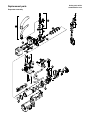
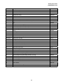
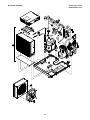
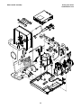
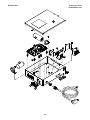
Replacement parts
Table of contents
4
5
7
7
7
7
7
12
12
13
14
14
15
15
15
15
15
16
17
17
17
18
18
21
25
25
25
26
26
26
26
26
27
28
31

4
Welcome to Follett
Follett equipment enjoys a well-deserved reputation for excellent performance, long-term reliability and
outstanding after-the-sale support. To ensure that this equipment delivers the same degree of service, we ask
that you review the installation manual (provided as a separate document) before beginning to install the unit.
Our instructions are designed to help you achieve a trouble-free installation. Should you have any questions or
require technical help at any time, please call our technical service group at (877) 612-5086 or +1 (610) 252-
7301.
Before you begin
After uncrating and removing all packing material, inspect the equipment for concealed shipping damage. If damage
is found, notify the shipper immediately and contact Follett Corporation so that we can help in the ling of a claim,
if necessary.
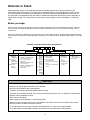
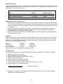
Check your paperwork to determine which model you have. Follett model numbers are designed to provide information
about the type and capacity of Follett equipment. Following is an explanation of the different model numbers in the 700
series.
A V SC 700HC
ConfigurationApplication
S RIDE
®
(RIDE remote ice
delivery equipment)
T Top-mount
400 up to
454 lbs
(206kg)
700 up to
750 lbs
(340kg)
1000 up to
1036 lbs
(471kg)
1400 up to
1450 lbs
(658kg)
1650 up to
1580 lbs
(717kg)
V Vision™
H Harmony™
B Ice storage
bin
J Drop-in
M Ice Manager™
diverter valve
system
CondenserSeriesVoltageMachine
C 208-230/60/1 (icemaking head)
Self-contained only.
D 115/60/1 (icemaking head)
Self-contained and remote.
If remote unit, high side is
208-230/60/1.
E 230/50/1 (icemaking head)
Self-contained only.
F 115/60/1 (icemaking head)
Remote only. High side is
208-230/60/3.
MC Maestro™
Chewblet
(400 Series)
HC Horizon
Chewblet
(1000, 1400,
1650 Series)
HM Horizon
Micro
Chewblet
A Air-cooled, self-contained
W Water-cooled,
self-contained
R Air-cooled, remote
condensing unit
N Air-cooled, no condensing
unit for
connection to parallel rack
system
Chewblet
®
Ice Machine Model Number Configurations
CAUTION
• Warranty does not cover exterior or outside installations.
• Moving parts. Do not operate with front cover removed.
• Hot parts. Do not operate with cover removed.
• To reduce risk of shock, disconnect power before servicing.
• To prevent circuit breaker overload, wait 15 minutes before restarting this unit. This allows the compressor to
equalize and the evaporator to thaw.
• Drain line must be vented.
• Water supply must be treated by a scale-inhibiting lter.
• Most ice machine cleaners contain citric or phosphoric acid, which can cause skin irritation. Read caution
label on product and follow instructions carefully.
• Ice is slippery. Maintain counters and oors around dispenser in a clean and ice-free condition.
• Ice is food. Follow recommended cleaning instructions to maintain cleanliness of delivered ice.

5
Speci cations
Electrical
Each ice machine requires its own separate circuit with electrical disconnect within 10 ft (6m).
Equipment ground required.
Standard electrical:
HCC700: 208-230/60/1 (6 ft (2m) NEMA 6-15 cord and plug provided)
HCD700: 115/60/1 (6 ft (2m) NEMA 5-15 cord and plug provided)
Maximum ice machine fuse – 15A each
Amperage: 115V: 10A, 220V: 5A
Plumbing
3/8" OD push-in water inlet
3/4" MPT drain
1/4" FPT condenser inlet (water-cooled condenser only)
1/4" FPT condenser drain (water-cooled condenser only)
Notes: 3/4" vented drain line must slope a minimum of 1/4" per foot (6mm per 30.4cm run).
Drain to be hard piped and insulated.
To prevent back ow, do not connect drains.
Separate drains for ice machine and condenser.
Water shut-off recommended within 10 feet (3m).
Water supply must be treated by a scale-inhibiting lter (Follett item# 00130286).
Ambient
Air temperature 100 F/38 C max. 50 F/10 C min.
Water temperature 90 F/32 C max. 45 F/7 C min.
Water pressure – potable 70 psi max. (483 kPa) 10 psi min. (89 kPa)
Note: Water-cooled condenser pressure 150 psi (1034 kPa)
Heat rejection
Air-cooled rejects 8850 BTU/hr
Water-cooled rejects 10150 BTU/hr
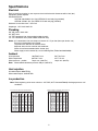
Ice production
Note: Water regulating valve set to maintain a 215 PSIG (95°F Saturated R404A) discharge pressure at all
conditions.
F
C
50
10
60
16
70
21
80
27
90
32
60
16
747
339
714
324
671
304
649
294
600
272
70
21
678
308
673
305
643
292
609
276
583
264
80
27
644
292
618
280
589
267
561
254
535
243
90
32
586
266
559
254
528
239
506
230
499
226
100
38
565
256
529
240
512
232
478
217
441
200
lbs
kg
lbs
kg
lbs
kg
lbs
kg
lbs
kg
Potable Water Temperature F/C
Ambient Air Temperature F/C
Air-cooled ice machine capacity/24 hrs.
F
C
50
10
60
16
70
21
80
27
90
32
60
16
672
305
600
272
544
247
521
236
506
230
70
21
665
302
597
271
541
245
515
234
504
229
80
27
660
299
584
265
539
244
506
230
501
227
90
32
656
298
582
264
535
243
504
229
500
227
lbs
kg
lbs
kg
lbs
kg
lbs
kg
lbs
kg
Potable Make-up Water Temperature F/C
Condenser Water Temperature F/C
Water-cooled ice machine capacity/24 hrs.

6
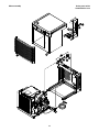
Dimensions and clearances
Entire front of ice machine must be clear of obstructions/connections to allow removal.
1" (26mm) clearance above ice machine for service.
1" (26mm) minimum clearance on sides.
The intake and exhaust air grilles must provide at least 160 sq in (1032 sq cm) of open area.
Air-cooled model HCC700A ice machines – 18" (458mm) minimum clearance between discharge and air
intake-grilles.
22.46" (57 cm)
1.75 MIN.22.44
" (57 cm)
21.25
"
(54 cm)
3/8"OD PUSH-IN WATER INLET
3/4" MPT DRAIN
1/4" FPT CONDENSER
(WATER COOLED ONLY)
ICE TRANSPORT HOSE CONNECTION
AIR EXHAUST

77
Operation
Cleaning and preventive maintenance (all models)
Note: Do not use bleach to sanitize or clean the icemaker.
Preventive maintenance
Periodic cleaning of Follett’s icemaker system is required to ensure peak performance and delivery of clean,
sanitary ice. The recommended cleaning procedures that follow should be performed at least as frequently as
recommended, and more often if environmental conditions dictate.
Cleaning of the condenser can usually be performed by facility personnel. Cleaning of the icemaker system,
in most cases, should be performed by your facility’s maintenance staff or a Follett authorized service agent.
Regardless of who performs the cleaning, it is the operator’s responsibility to see that this cleaning is performed
according to the schedule below. Service problems resulting from lack of preventive maintenance will not be
covered under the Follett warranty.
Weekly exterior care
The exterior may be cleaned with a stainless cleaner such as 3M Stainless Steel Cleaner & Polish or equivalent.
Monthly condenser cleaning (air-cooled icemaker only)
1. Use a vacuum cleaner or stiff brush to carefully clean condenser coils of air-cooled icemakers to ensure
optimal performance.
2. When reinstalling counter panels in front of remote icemakers, be sure that ventilation louvers line up with
condenser air duct.
Semi-annual evaporator cleaning (every 6 months)
WARNING
• Wear rubber gloves and safety goggles (and/or face shield) when handling ice machine cleaner or sanitizer.
CAUTION
• Use only Follett approved SafeCLEAN™ Cleaner (part #00132001) and NU-CALGON IMS-II SANITIZER
(00979674).
• Do not mix Cleaner and Sanitizer solutions together.
• DO NOT USE BLEACH.
• It is a violation of Federal law to use these solutions in a manner inconsistent with their labeling.
• Read and understand all labels printed on packaging before use.
Note: Complete procedure for cleaning an sanitizing MUST be followed. Ice must be collected for
10minutes before putting ice machine back into service.
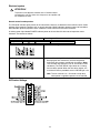
1. To clean – Remove cover. Press the CLEAN button.
The machine will drain. Wait for the LO WATER light
to come on (Fig. 1).
LO WATER
Fig. 1

88
2. Mix 1 gallon (3.8L) 120 F (49 C) water and
7 ounces (198g) (one 7 ounce packet of Follett
SafeCLEAN ice machine cleaner, part# 00132001).
Locate cleaning cup. Fill until CLEANER FULL light
comes on (Fig. 2).
Note: Do not use bleach to sanitize or clean the
icemaker.
CLEANER
FULL
Fig. 2
15
Fig. 3
LO WATER
Fig. 4
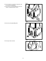
3. Replace cover on cleaning cup. Wait until machine
restarts. Machine will clean, then ush 3 times in
approximately 15 minutes (Fig. 3).
4. To sanitize – Press CLEAN button. The machine
will drain. Wait for LO WATER light to come on
(Fig. 4).

99
CLEANER
FULL
Fig. 5
15
Fig. 6
Fig. 7
5. Mix 1 gallon 120 F (49 C) water and 1.6 ounces
(48ml) NU-CALGON IMS-II SANITIZER. Fill until
CLEANER FULL light comes on (Fig. 5).
Place one Sani-Sponge
™
in remaining sanitizing
solution and retain for Step 9.
Note: Do not use bleach to sanitize or clean the
icemaker.
6. Replace cover on cleaning cup. Wait until machine
restarts. Machine will sanitize, then ush 3 times in
approximately 15 minutes (Fig. 6).
7. Disconnect coupling as shown (Fig. 7).
Note: Steps 8-11 must be completed before
machine ushes and starts producing ice.

1010
Fig. 8
1
2
3
16"
(407mm)
Fig. 9
Fig. 10
8. Using disposable food service grade gloves, insert
dry Sani-Sponge
™
(kit part# 00132068). Next,
insert Sani-Sponge soaked in Nu-Calgon IMS-II
sanitizer solution (from Step 5). Push both Sani-
Sponges down ice transport tube with supplied
pusher tube(Fig.8).
9. Remove and discard 16" (407mm) pusher tube
(Fig. 9).
10. Reconnect coupling. When sanitizing cycle ends,
machine will start producing ice. Press power
switch ON. Ice pushes Sani-Sponges through tube
(Fig. 10).

1111
Fig. 11
11. Place a sanitary (2 gallon or larger) container in
bin or dispenser to collect Sani-Sponges and ice
for 10 minutes. Collect 5.5 lbs (3kg) of ice from unit.
Discard ice and Sani-Sponges (Fig. 11).

12
Service
Ice machine operation (all models)
Follett’s ice machine consists of ve distinct functional systems covered in detail as follows:
• Water system
• Electrical control system
• Mechanical assembly
• Refrigeration system
• Bin full
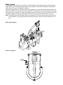
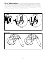
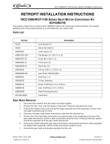
The Horizon ice machine overview
The Follett Horizon ice machine uses a horizontal, cylindrical evaporator to freeze water on its inner surface. The
refrigeration cycle is continuous; there is no batch cycle. The evaporator is ooded with water and the level is
controlled by sensors in a reservoir. A rotating auger (13 RPM) continuously scrapes ice from the inner wall of the
evaporator. The auger moves harvested ice through the evaporator into an ice extrusion canal. The ice is forced
through a restrictive nozzle that squeezes out the water and creates the Chewblet. The continuous extrusion process
pushes the Chewblets through a transport tube into a dispenser or bin.
A solid state PC board controls and monitors the functionality of the ice machine. In addition to sequencing electrical
components, the board monitors various operational parameters. A full complement of indicator lights allows visual
status of the machine's operation. Additionally, the PC board controls the self- ushing feature of the ice machine. The
evaporator water is periodically drained and replenished to remove minerals and sediment.
A unique “bin full” detection system is incorporated in the Horizon ice machine. A switch located at the ice discharge
port of the machine detects the position of the transport tube. When the bin lls up with ice, the transport tube
moves out of the normal running position, and the switch turns the ice maker off. A domed housing at the end of the
transport tube contains the ice extrusion loads during shut down.
Ice Transport Tube
Compression
Nozzle
Auger
Water Inlet
Harvest system diagram

13
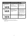
Water system
The water level in the evaporator is controlled by a feed solenoid and level detecting sensors. Referencing the
diagram below, water sensing rods extend down into the reservoir at the end of the evaporator assembly. The
system works via electrical conductivity as follows:
One of the longest probes is a common. When water is between any of the other probes and the common, the
PC board will sense the activation. During normal operation, the water level rises and falls between the Normal
High and Normal Low sensors. As water is consumed to make ice, the level will fall until the Normal Low sensor
is exposed, triggering the water feed solenoid on. Water will ll until the Normal High sensor is activated.
Note: The potable water dissolved solids content must be greater than 10 ppm for the water control system to
function properly. If using reverse osmosis water ltration system, ensure T.D.S level is greater than 10
ppm.
NORMAL
OPERATING
RANGE
NORMAL HI
NORMAL LO
COMMON
ALARM LO
Water system diagram
Water level diagram

14
Electrical system
ATTENTION!
To prevent circuit breaker overload, wait 15 minutes before
restarting this unit. This allows the compressor to equalize and
the evaporator to thaw.
Normal control board operation
The PC board indicator lights provide all the information necessary to determine the machine's status. Green
indicator lights generally represent “go” or normal operation; Yellow indicators represent normal off conditions;
Red indicators generally represent alarm conditions, some of which will lock the machine off.
A ashing green light labeled POWER indicates power to the machine. All other normal operation status
indicators are covered as follows:
Ice machine disposition Operating conditions
FLASHINGON or OFF
Legend:
OFFON
1. Ice machine is making ice.
.
1. Normal running.
2. Ice machine is not making ice. 2. Normal time delay. When the bin lls with ice, the LOW
BIN light goes out momentarily and the refrigeration
and auger drive systems immediately shut down. (Note:
The fan motor will continue to run for 10 minutes to cool
condenser) The TIME DELAY light comes on, initiating
the time delay period. When the time delay expires, the
machine will restart provided that the LOW BIN light is on.
Note: The ice machine has a 15-minute startup delay
when power is applied to prevent circuit overload.
DIP Switch Settings

15
Error faults:
The Horizon PC board monitors various operating parameters including high pressure, auger gearmotor
amperage limits, clogged drain, and low water alarm conditions. There are two types of errors namely “hard” or
“soft”. A hard error is one that shuts the machine off and will not allow restart until the reset button is pressed.
Even cycling power will not reset a hard error. A soft error can either be automatically reset should the condition
rectify, or if power is cycled. Should an error occur, consult the troubleshooting guide in this manual or a Follett
service technician.
Soft errors:
HI AMPS: The PC board monitors the amperage of the auger motor. Should the gear motor experience current
draw above the allowable limit, the machine will shut down and the TIME DELAY and HI AMP will be illuminated.
After the time delay the machine will restart and the TIME DELAY and HI AMP will clear.
LO WATER: During operation, the water level cycles between the normal low and normal high sensors. Should
the water be shut off to a running machine, a soft error will occur. The error sequence is as follows: During
operation, the water level falls to the normal low sensor, and when it does the water feed solenoid is energized.
If water is not detected at the normal low sensor within 10 seconds, a soft error will occur. The machine will shut
down, but the water feed solenoid will remain energized. Should water return, it will ll to the normal low sensor
and the machine will resume normal operation. The error will clear automatically.
HI PRESSURE: Should the refrigeration pressure rise above 425 psi, the machine will shut down and the TIME
DELAY and HIGH PRESSURE will be illuminated. After the time delay, and if the pressure has fallen back below
the reset point of 295 psi, the machine will restart and the TIME DELAY and HIGH PRESSURE will clear.
Hard error:
DRAIN CLOG: The drain clog sensor, located in the chassis, underneath the rear drain pan, will detect the
presence of water just below the top edge of the pan. If water does not properly ow out of the drain pan it will
over ow into the chassis and rise to the sensor (especially during a self- ushing purge cycle). Pressing the reset
button will restart the ice machine.
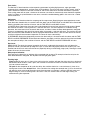
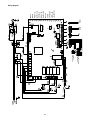
Relay output indication:
Each relay on the board has an indicator light associated with its output. For example, when the relay for the
water feed solenoid is energized, the adjacent indicator light glows green.
Flushing logic
Flush on y: For every one (1) hour of ice making time, the machine will open the drain valve for a duration of
60 seconds. While the drain valve is open, the machine will continue to make ice and the water feed valve will
cycle to maintain water level.
Off cycle: At the completion of off-cycle time delay, the machine checks for a cumulative one (1) hour of ice
making time since the last off-cycle ush. If the cumulative ice making time exceeds one (1) hour, the machine
will open the drain valve for 60 seconds to drain the evaporator in its entirety. It will then re ll with water and
begin making ice. If the ice making time is less than 1 hour, the machine will start and begin making ice
without draining the evaporator.

16
CLEANER FULL
DRAIN CLOG
HI PRESSURE
HI AMPS
SERVICE
MAINT/CLEAN
LOW WATER
TIME DELAY
SLEEP CYCLE
MAKING ICE
LOW BIN
POWER
HIGH
PRESS
MAINT.
CLEAN
BIN
RESERVOIR
WATER SENSOR
DRAIN CLOG
SENSOR
WHITE OR
GRAY
BLUE OR
PINK
BLACK
AUGER
Wiring diagram

17
Compressor data
Compressor current draw at 115 VAC
Air/Water-cooled 60 F/15.5 C 70 F/21.1 C 80 F/26.7 C 90 F/32.2 C 100 F/37.8 C
8.25A 8.12A 8.15A 8.20A 8.89A
Locked rotor amps 50A @ 115V
Compressor current draw at 208-230 VAC
Air/Water-cooled 60 F/15.5 C 70 F/21.1 C 80 F/26.7 C 90 F/32.2 C 100 F/37.8 C
4.13A 4.06A 4.08A 4.10A 4.45A
Locked rotor amps 31A @ 208-230V
Gearmotor data
Gearmotor current 1.2A @ 115V
0.62A @ 208-230V
Gearmotor torque-out (high amp) trip point: 1.8A @ 115V
1.2A @ 208-230V
Locked rotor amps 2A @ 115V
1.4A @ 208-230V
Resistance of windings
115 vac gearmotor:
White to black: 16Ω
White to blue: 16Ω
Blue to black: 32Ω
208-230 vac gearmotor (Brother):
White to black: 36Ω
White to tan: 36Ω
Tan to black: 72Ω
Compressor start winding (115V) 10.43Ω
Compressor run winding (115V) 1.77Ω
Compressor start winding (208-230V) 5.95Ω
Compressor run winding (208-230V) 0.69Ω
Fan motor 38Ω
Fan motor data
Fan motor current 1.35A @ 115V
0.65A @ 208-230V

18
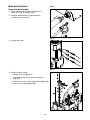
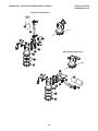
Mechanical System
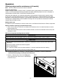
Fig. 12
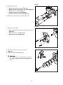
Evaporator disassembly
1. Press CLEAN button to purge evaporator. Turn
power OFF when LO WATER lights.
2. Unscrew and disconnect transport tube from
louvered docking assembly.
Fig. 13
3. Unplug gear motor.
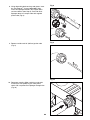
Fig. 14
4. Remove shuttle housing:
§ Remove vent tube (Fig. 14.1).
§ Disconnect shuttle housing switch connections
(Fig.14.2).
§ Remove two screws and lift shuttle housing (Fig. 14.3).
§ Remove stream divider (Fig. 14.4).
1
3
2
4

19
Fig. 15
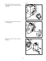
5. Remove gear motor:
§ Remove gear motor insulation (Fig. 15.1).
§ Remove 1/4-20 screw, retainer, and spacer (Fig. 15.2).
§ Remove two 1/2" bolts (Fig. 15.3).
§ Pull gear motor from auger (Fig. 15.4).
§ Remove main housing insulation (Fig. 15.5).
6. Remove all traces of petro-gel from auger shaft.
1
2
3
3
5
4
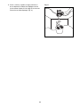
Fig. 16
7. Remove main housing:
§ Use an allen wrench to remove 3/16" allen screws (3)
(Fig. 16.1).
§ Remove shaft insulation (Fig. 16.2).
§ Remove main housing (Fig. 16.3).
1
2
3
1
1
Fig. 17
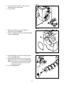
8. Remove and discard mating ring and seal
(Fig.17.1).
9. Carefully remove auger (Fig. 17.2).
WARNING!
Use caution when removing auger. The auger is
very sharp - handle with care to avoid personal
injury.
1
1
2

20
Fig. 18
10. Press the lever on the back of the reservoir
(Fig.18.1) to release and remove the solenoid
(Fig.18.2).
1
2
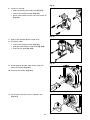
Fig. 19
11. Remove three screws to remove the reservoir
insulation (Fig.19).
Fig. 20
12. Remove three screws to remove the reservoir
(Fig.20).
Page is loading ...
Page is loading ...
Page is loading ...
Page is loading ...
Page is loading ...
Page is loading ...
Page is loading ...
Page is loading ...
Page is loading ...
Page is loading ...
Page is loading ...
Page is loading ...
Page is loading ...
Page is loading ...
Page is loading ...
Page is loading ...
Page is loading ...
Page is loading ...
Page is loading ...
Page is loading ...
Page is loading ...
Page is loading ...
Page is loading ...
Page is loading ...
-
 1
1
-
 2
2
-
 3
3
-
 4
4
-
 5
5
-
 6
6
-
 7
7
-
 8
8
-
 9
9
-
 10
10
-
 11
11
-
 12
12
-
 13
13
-
 14
14
-
 15
15
-
 16
16
-
 17
17
-
 18
18
-
 19
19
-
 20
20
-
 21
21
-
 22
22
-
 23
23
-
 24
24
-
 25
25
-
 26
26
-
 27
27
-
 28
28
-
 29
29
-
 30
30
-
 31
31
-
 32
32
-
 33
33
-
 34
34
-
 35
35
-
 36
36
-
 37
37
-
 38
38
-
 39
39
-
 40
40
-
 41
41
-
 42
42
-
 43
43
-
 44
44


Follett HCC700A Operation And Service Manual
- Category
- Ice cube makers
- Type
- Operation And Service Manual
Ask a question and I''ll find the answer in the document
Finding information in a document is now easier with AI
Related papers
-
Follett HME700A Operation And Service Manual
-
Follett horizon elite HMC1010A/W Operation And Service Manual
-
Follett HMD1000N Operation And Service Manual
-
-
-
-
-
-
-
Other documents
-
 Cornelius UC700-A User manual
-
Manitowoc Ice SF0400 SN0450 SF0600 SN650 SF0900 SN950 1ph Product information
-
Cornelius WCC1401-A Series User manual
-
 Cornelius Series 200 Installation guide
-
 IMI Cornelius, Inc. 200 Installation guide
-
-
 Cornelius Nordic Elite series User manual
-
Ice-O-Matic GEMD790 User manual
-
 Cornelius 1400 User manual
-
 IMI Cornelius, Inc. WCF1100 Installation guide


