Page is loading ...

Page 1
L154 0810B
U
L
CUS
R
Read and Save These Instructions
All Hoods Must Be Installed By A Qualied Installer
INSTALLATION INSTRUCTIONS
WALL MOUNT LINER INSERT WITH
M600 OR M1200 BLOWER
Read All Instructions Thoroughly Before Beginning Installation
WARNING - TO REDUCE THE RISK OF FIRE, ELECTRIC SHOCK,
OR INJURY TO PERSONS, OBSERVE THE FOLLOWING:
A. Installation work and electrical wiring must be done by qualied
person(s) in accordance with all applicable codes and standards,
including re-rated construction. Switch power off at service panel
and lock the service disconnecting means to prevent power from
being switched on accidentally during installation.
B. When cutting or drilling into wall or ceiling, do not damage electrical
wiring and other hidden utilities.
C. Ducted fans must always be vented to the outdoors.
D. Sufcient air is needed for proper combustion and exhausting
of gases through the ue (chimney) of fuel burning equipment to
prevent back drafting. Follow the heating equipment manufacturer’s
guideline and safety standards such as those published by the
National Fire Protection Association (NFPA), and the American
Society for Heating, Refrigeration and Air Conditioning Engineers
(ASHRAE), and local code authorities.
WARNING - TO REDUCE THE RISK OF FIRE, USE ONLY METAL
DUCTWORK

Page 2
L154 0810B
Ducting Do’s and Don’ts
NEVER restrict the duct size. The single blower unit (M600) requires 6” round duct or equivalent
(28 square inches), and the dual blower unit (M1200) requires 10” round duct or equivalent
(79 square inches). Using Vent-A-Hood ducting products (back page) will ensure proper
efciency.
Blower Duct Size Sq. Inch Area Vent-A-Hood Transition
Single (M600) 6” round or equivalent 28” N/A
Dual (M1200) 10” round or equivalent 79” VP566 (Inlcuded)
Do not use exible or corrugated duct. This type of duct will restrict airow and reduce
performance. Only use smooth, galvanized, metal duct. Observe local codes regarding special
duct requirements and placement of duct against combustibles. Make the duct run as short
and as straight as possible with as few turns as possible. Avoid sharp-angled turns. Instead,
use smooth, gradual turns such as adjustable elbows or 45 degree angled turns. For duct runs
over 20 feet, increase the duct diameter by one inch for every ten feet of duct. A 90 degree
elbow is equal to 5 feet of duct. Using Vent-A-Hood roof jacks or wall louvers (back page) will
ensure proper efciency. Airow must not be restricted at the end of the duct run. Do not use
screen wire or spring-loaded doors on wall louvers or roof jacks. Do not terminate venting into
an attic or chimney. Where possible, seal joints with duct tape. The hood must be ducted to the
outdoors without restrictions.
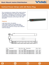
YES
NO
Smooth Duct Smooth Gradual Turn Proper Combining
of Two Ducts
Flexible Duct
Sharp Angled Turns Improper Combining
of Two Ducts

Page 3
L154 0810B
Electrical
10" Round
Centerline
of Hood
6" Round
Electrical
Centerline
of Hood
Installation Details
1) Read all instructions thoroughly before beginning installation. Note: These instructions apply to standard liners only.
Custom liners may require additional specication consideration.
2) When installing a MSLD wall mount liner (19 1/4” deep), it is recommended that the bottom edge of the liner be located
no more than 24” - 27” from the cooking surface. For MPSLD wall mount liners (22 1/2” deep), it is recommended that
the bottom edge of the liner be located no more than 27” - 30” from the cooking surface. Exceeding recommended
mounting height may compromise performance.
3) Install the duct from the outside of the home down to the location of the exhaust outlet on the top of the liner allowing
room for the transition (if applicable). If a transition is used, install duct down to the location of the transition outlet
plus 1”. This will allow the transition to engage 1” inside of duct. Consult the connection diagrams (below) for further
details on exhaust outlet placement.
Use duct tape to seal all joints. A complete listing of available Vent-A-Hood ducting materials is included on the back
page of this instruction sheet.
Transition heights are as follows:
Single Blower (M600): 6” round duct will connect directly to the top of the liner.
Dual Blower (M1200): Included 10” round transition (VP566) is 9” tall.
MSLD Liner MPSLD Liner
M1200 Connection Diagram
Dual Blower
(Top View)
Single Blower
(Top View)
M600 Connection Diagram

Page 4
L154 0810B
Installation Details Continued
4) Remove the liner from its packaging and place it back side down on the oor or countertop in front of the wall where
it will hang.
5) Remove the nuts retaining the safety straps on the inside ends of the liner shell. Pull the safety straps off of the studs
to disengage. Separate the lower lter/control section from the liner shell by pulling them apart. These sections only are
held together by snaps once the safety straps are disengaged. Disconnect the electrical power cord from the reverse
side of the lter/control section. Set the lter/control section aside.
Warning: Make sure power is off and locked at the service disconnecting
means on the service panel during installation.
6) Liner shells are shipped from the factory with the junction box mounted for the M1200 double blower conguration.
Remove the junction box cover. If the M600 single blower will be used, relocate the junction box and ground strap to
the offset location. Install an appropriate 1/2” UL listed electrical wire clamp through the electrical opening on top of
the liner shell. Install electrical wiring from the service panel to the liner location. Consult the connection diagrams
(on previous page) for further details on electrical placement.
Model Volts Amps* Hz
CFM
CFM
CFM
CFM
CFM
Minimum Round
Duct Size
M600 Single 115 5.0 60 630 625 615 600 580 6" (28 in.
2
)
M1200 Dual 115 10.0 60 1035 1015 1000 955 915 10" (79 in.
2
)
* Add 0.5 amp for each halogen light. 2 lights: 30" - 41", 3 lights: 42" - 53", 4 lights: 54"-66"
7) For M600 single blower installation, skip to Step 8. Install the 10" transition (VP566, included) to the top of the liner
shell with the screws provided. Seal the base of the transition to the hood with duct tape.
8) Extend wires to the liner shell and insert them into the electrical wire clamp on the junction box. Tighten the wire clamp.
From inside the liner, using UL listed wire nuts, attach the “neutral” wire to the white lead, the “hot” wire to the black
lead, and the ground wire to the green lead inside the junction box. Replace the junction box cover.
Warning: Do not operate hood without proper ground connection.
9) Taped inside the liner behind the lters is a drill template/spacing tool. This tool will be used to locate the pilot mounting
holes for the four corners of the liner shell and set the spacing between the bottom of the liner shell and the bottom
of the decorative enclosure.
Ready a power drill with a 3/32” drill bit to have within reach while working inside of the decorative enclosure. Hold
the template with the long side standing up and the short side pointing left. Place the long side of the template against
the inside of the left end of the enclosure. Slide the template up until the short side of the template rests against the
bottom of the enclosure. Now slide the template along the bottom of the enclosure until the edge of the template rests
against the back of the enclosure. The hole in the template is now in the location of the back left liner shell mounting
screw. Drill a shallow pilot hole taking care not to drill through the decorative enclosure.
Slide the template along the bottom of the enclosure until the edge of the template rests against the front of the
enclosure. The hole in the template is now in the location of the front left liner shell mounting screw. Drill a shallow
pilot hole and repeat for the front and rear mounting holes on the right end of the decorative enclosure.
10) While guiding the wires, lift the liner shell into the enclosure about 1-1/2" up from the bottom edge of the decorative
enclosure taking care to properly align the duct connection (M1200 blower). Wood strips may be necessary to ll any
gaps between the opening and the liner if the opening in the surround is larger than the liner. Loosely install a wood
screw (included) into the four slotted corner holes along the bottom edge of the liner shell.
11) Hold the template with the short side standing up and the long side pointing left. Place the short side of the template
against the inside of the left end of the enclosure. Move the shell liner up or down in the slotted holes until the bottom
of the shell liner is ush with the top of the short side of the spacing tool. Move the tool to all four bottom corners of
the enclosure and adjust the shell liner position until the spacing tool ts properly all around. Tighten the four corner
screws.

Page 5
L154 0810B
Installation Details Continued
12) To conrm a ush alignment into the decorative enclosure, temporarily snap the lter/control section into the liner
shell. Adjust corner screws if necessary.
13) Unsnap the lter/control section from the bottom of the liner shell and insert wood screws (included) in the remaining
holes along the bottom edge of the liner shell.
14) Raise the blower plate into the liner shell rst aligning the ducting (M600 blower only) and then aligning the blower
mounting studs to the holes in the blower plate. Secure the blower assembly with the nuts provided. This duct connection
typically cannot be sealed.
15) Hold the lter/control section just below the liner shell and connect the motor harness and power cord to the sockets
in the lter/control section electrical cover. Snap the lter/control section to the bottom of the liner shell. Secure the left
and right lter/control section safety straps to the studs on the inside ends of the liner shell with the nuts previously
removed in Step 5.
16) To install the bafe lter, hold the lter with the knob facing down and toward the front of the hood. Insert the back of
the lter into the back lter channel with enough force to compress the lter spring. Raise the front of the lter inline
with the front lter channel and slowly release the spring force.
To remove the bafe lter, push the lter knob toward the back lter channel to compress the lter spring. Lower the
front of the lter below the front lter channel and slowly release the spring force.
17) Refer to the Owner Maintenance Guide Operating Instructions for proper hood operation. Test all blower and light
functions to ensure they are operating properly.

Page 6
L154 0810B
VENTING ACCESSORIES
6” RECTANGULAR DUCT PIPE
MODEL DIM
VP507 6” x 8 ½”
24”
8 ½”
6”
ROUND DUCT PIPE
MODEL DIM
VP500
VP501
VP502
6” Round
7” Round
8” Round
36”
6”
7”
8”
3 ¼” RECTANGULAR DUCT PIPE
MODEL DIM
VP504
VP505
VP506
3 ¼” x 10”
3 ¼” x 12”
3 ¼” x 16”
30”
10”
12”
16”
3 ¼”
OFFSET L & R TRANSITION
FOR ISLAND BLOWERS
MODEL DIM
VP542
VP543
Top Left
Top Right
8”
12”
5”
16”
SIDE VENT TRANSITION L & R
FOR ISLAND BLOWERS
MODEL DIM
VP544
VP545
Left Side
Right Side
19”
8”
16”
5”
OFFSET KIT - RECTANGULAR
MODEL DIM
VP550 6” Rnd to 3 ¼” x 10”
16”
11”
6”
11”
3 ¼”
10”
STANDARD ISLAND TRANSITION
MODEL DIM
VP565 5” x 16” to 8”
8”
9”
16”
5”
CLUSTER BLOWER TRANSITION
MODEL DIM
VP564 8” & 8” to 12”
18 ½”
12”
11 ¼”
“Y” TRANSITION
MODEL DIM
VP517
VP518
VP551
8” & 8” to 12”
6” & 8” to 12”
6” & 8” to 10”
18”
10”
12”
3 ¼” x 10” BACK VENT ELBOW
MODEL DIM
VP559 3 ¼” x 10”
4 ¼”
10”
14”
3 ¼”
3 ¼”
MULTI-BLOWER TRANSITION
MODEL DIM
VP562
VP563
6” & 8” to 10”
8” & 8” to 12”
VP562 - 17 ½”
VP563 - 16 ½”
10”
12”
VP562 - 23 ¼”
VP563 - 30 ½”
3 ¼” x 10” TO 7” TRANSITION
MODEL DIM
VP521 3 ¼” x 10” to 7”
7”
7 ½”
3 ¼”
10”
LOW PROFILE ROOF JACK
(MAXIMUM 4/12 PITCH)
MODEL DIM
6 ½”
VP539
VP540
VP541
6” Round
7” Round
8” Round
/