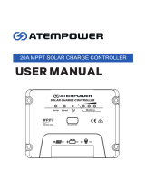
MPPT Solar Charge Controller
4 STAGE CHARGING
SC420/ND
SC440/ND
P/No. SC420/ND, SC440/ND
Pictured: SC420

1. Safety Tips
• Please ensure the instructions are read prior to any installation.
• Keep instructions in a safe place for future reference.
• SC420 and SC440 are designed for indoor use only
• Beware of any nearby electrical equipment that may interfere with installing this device.
DonotconnectanyACsourcestothecontrollerasitmaycauseare/explosionandwillpermanently
damage the device.
• Always check the battery polarities before making a connection. The positive terminal of a battery goes
into BAT+ and the negative into BAT-.
• The controller is not designed to run without a battery voltage reference. In the event of replacing
servicingthebattery,alwaysdisconnectthesolarinputrst(orfullycoverthepanels),thenreplace/
service the battery.
• Solar panels can generate high voltages and currents, make sure your solar panels are completely
covered from sunlight during installation.
• Keep this product out of reach of children.
• Always install a fuse on both the input positive and output positive circuit.
• Connecting wires to this device can generate sparks, please wear proper insulation gear
while installing this device.
• Thiscontrollerisanegativegrounded(positiveswitching)type.
• Always take the total length of wire into consideration and use the correct wire size, see below for a
table of recommended wire size for various current loads.
•Leadacidbatteriescanbedangerous.Ensurenosparksoramesarepresentwhenworkingnear
batteries.
Solar Input Current 5A 10A 20A 30A 40A
Wire Cross Section Area (mm2) 1.5 2.5 5 8 10
Wire AWG 15 13 10 8 7

2. Product Features
• 4 Stage charging ensures the battery is charged to the optimum level
• AdvancedMPPTtechnologytoimprovechargingefciencyindifferentweather
and temperature conditions
• Tempered glass cover with screen touch operation and sturdy aluminium housing
• Selectable battery chemistry types, including AGM, GEL, WET and Lithium
• Auto recognition of 12V/24V battery system voltage
• Protects your battery from discharge at night. Under low light or no light conditions, the solar panel
voltage could be less than the battery voltage. The controller contains circuitry which prevents current
owingbackfromthebatteryandintothesolarpanel
• Multi charging protections against reverse polarity, over-voltage and over-temperature.
• Withtheuseofabatterytemperaturesensor(optional),thecontrollerwillcompensatecharging
voltageswhenthebatterytemperaturebecomestoohigh(ForLeadacidonly).
• Supports remote display for monitoring additional parameters, such as charging watt-hours,
charging current and solar input voltage.

3. Device Diagram
# Description # Description
1 LCD Display Screen 6 External Temperature Sensor Port
2 LED Indicator (PV, BAT, FAULT) 7 RS485 Communication Port
3 Touch Screen Button 8 Solar Input Terminals
4 Installation Mounting Holes 9 Battery Terminals
5Grounding Terminal 10 Magnetic Cover
1
2
109876
3
4
5

4. Wiring Instructions
5. Wiring Sequence
1 & 2: Remove the magnetic cover, and put it aside 3. Unscrew the terminals completely,
before inserting any wiring leads.
4. Insert the bare wire side of the cable to the
terminal, and tighten the screws.
5. Check the wiring condition and put the
magnetic cover back.
Grounded
Remote LCD Meter
1. Connect the positive battery wire followed by the negative battery wire.
2. Connect the positive solar array input wire followed by the negative solar array input wire
(makesureyoursolarpanelsarefullycoveredtopreventelectricalshock)
3. Connecttheexternaltemperaturesensor(optional)toitsterminalshownabove,andplacethesensor
on the side of a battery.
4. ConnecttheexternalremoteLCDthroughRS485communicationport(ifapplicable)
The controller is not designed to run without a battery voltage reference. In the event of replacing/servicing the
battery, always disconnect the solar input or fully cover the panels, then remove/replace the battery.

6. Operation
6.1 Voltage auto-recognition
System startup: When the battery is connected, the system will automatically recognise the system voltage
andbrieydisplaythisontheLCDdisplay.
6.2 LCD Display Cycle
Short press the touch screen button will cycle through the following four displays:
- Battery Voltage
- Battery SOC
- Temperature
- Error Code
Toadjustthetemperaturescale(From°Cto°Fandvice-versa):
1. While the display is showing the temperature, long press the touch screen button to enter Set mode.
2. Short press the button to select the scale.
3.Longpressagaintoexitandsavethesettings.
6.3 Charging Stages
BulkCharge(Stage1)-UtilisingMPPTtechnology,thecontrollerwilldelivermaximumcurrentuntil
batteries rise to boost level.
BoostCharge(Stage2)-Oncethebatteryisalmostcharged,voltageisheldconstantfor2hours.
EqualizationCharge*(Stage3)-OnlyapplicabletoFlooded/WETandAGMmode.Every30days,itwill
skip boost and automatically run equalization to rejuvenate the internal battery cells.
FloatCharge(Stage4)-Onlyapplicabletonon-lithiumbatteries.Whenthebatteryisfullycharged,itwill
reducethevoltageto13.8Vtokeepthebatterytoppedup.
Stage 1
Stage 2
Stage 3
Stage 4

6.4 LED Indication Chart
LED Name LED Display Signal Indication
PV
Off Not In Charge
Steady On In Charge
BAT
Fast Flash Battery Over Voltage
Steady On Battery On & Normal
FAULT
Off No Error or Alarm
Steady On System with Error or Alarm

7. Parameters Setting
7.1 Selecting Battery Type
To select the battery type, long press the touch button while the display is not showing the temperature.
This will enter the battery set mode.
Short press while in this mode will cycle through the folowing chemistries:
GEL(default)-ForGeltypebatteries
L12-ForLithium12Vbatteries
L24-ForLithium24Vbatteries
FLD-ForWET/Floodedbatteries
SEL-ForSealedLead-acid/AGMbatteries
Toexitandsavethesetting,longpressthetouchbutton.
Key System Mode Operation Operation Description
View Mode
Short Press View Next Page
Long Press Enter SET mode
Set Mode
Short Press Select battery type or tempera-
ture scale
Long Press Exit SET Mode & save the
settings
7.2 Touching Button Chart
08/22
08/22
08/22
SOLAR CONTROLLER DISPLAY TO SUIT
SC420 AND SC440
P/NO: SC400D
08/22

8.2 Battery Temperature Sensor:
Asanoption,theunitprovidesaporttoconnecttheexternalbatterytemperaturesensor.Ifitisused,the
unit will optimise the charging performance subjected to the battery temperature
8. Error Code Chart
CODE Error Description Quick Troubleshoot
E00 No Error - -
E02 Battery
Over-voltage
Battery output voltage has
exceeded the controller’s max-
imum rating
Check whether there is an external voltage applied
to the battery
E06 Controller
Over-temperature
Controller has exceeded the
ambient temperature limit
Ensure the controller is placed
in a well-ventilated area.
E07 Battery Sensor
Over-temperature
The surrounding temperature
around the temperature
sensor is too high
Check the sensor is not near a hot source.
Battery may be faulty if it is too hot
E10 Solar Over-voltage
Solar input voltage has
exceeded the controller’s max-
imum rating
Lower the solar panel’s total voltage connected
to the controller
E13 Solar Reverse
Polarity
Solar input cables are
connected in reverse Disconnect and reconnect with the correct polarity
E14 Battery Reverse
Polarity
Battery output cables are
connected in reverse
Disconnect and re-connect with
correct wire polarity

9. Controller Specication
*When the battery voltage drops below 13.2V (26.4V for 24V systems), it will perform a normal charge cycle.
Controller
Parameter Specications
Model No. SC420/SC420-ND SC440/SC440-ND
System Wiring
Grounded Negative Grounded
Battery System
Voltage
12V/24V
Auto (FLD/GEL/SEL/USER)
Manual (Li/User)
12V/24V
Auto (FLD/GEL/SEL/USER)
Manual (Li/User)
No-load Loss 12mA/12V; 10mA/24V 12mA/12V;10mA/24V
Max Solar Input
Voltage <100Voc <100Voc
Rated Solar
Charge Current 20A 40A
Max Solar Input
Power
300W/12V
600W/24V
600W/12V
1200W/24V
Operating
Temperature -35ºC ~ +45ºC
Net Weight 1.2kg 1.9kg
Communication RS485
Controller
Dimensions 190*120*59mm 218*150*65mm
Battery Voltages Battery Parameters
Battery Types FLD SEL GEL
(default)
USER
(applicable only with
SC400D Remote
display)
LI
Equalization
Charge Voltage 14.8V / 29.6V 14.6V / 29.2V - Default -
Boost Charge
Voltage 14.6V / 29.2V 14.4V / 28.8V 14.2V / 28.4V Default: GEL 14.2V / 28.4V
Float Charge
Voltage 13.8V / 27.6V Default: GEL -
Boost Charge
Recovery Voltage* 13.2V / 26.4V Default: GEL -
Auto Temperature
Compensation -3mV/2V/ºC Default: GEL -
Accessory List Package Status
External
Temperature
Sensor
Yes
Remote LCD Meter Optional

10. Controller Dimensions
SC420, SC420-ND
Product Dimensions: 190*125*60mm
InstallationAreaDimensions:180*80mm
Installation Hole Size: 5*5mm
Connection Socket Size: 7.5*7.5mm
SC440, SC440-ND
ProductDimensions:218*150*65mm
Installation Area Dimensions: 205*60mm
Installation Hole Size: 5*5mm
Connection Socket Size: 7.5*7.5mm

IS516
Issue 1 11/11/22
WARRANTY STATEMENT
Brown&WatsonInternationalPtyLtd(“BWI”)of1500FerntreeGullyRoad,Knoxeld,
Vic.,telephone(03)97306000,fax(03)97306050,warrantsthatallproductsdescribedin
its current catalogue will under normal use and service be free of failures in material and
workmanshipforaperiodofthree(3)yearsfromthedateoftheoriginalpurchasebythe
customer as marked on the invoice. This warranty does not cover ordinary wear and tear,
abuse, alteration of products or damage caused by the purchaser.
To make a warranty claim the consumer must deliver the product at their cost to the
original place of purchase or to any other place which may be nominated by either
BWI or the retailer from where the product was bought in order that the warranty
assessment may be performed. The consumer must also deliver the original invoice
evidencingthedateandplaceofpurchasetogetherwithanexplanationinwritingas
to the nature of the claim.
In the event that the claim is determined to be for a minor failure of the product then BWI
reserves the right to repair or replace it at its discretion. In the event that a major failure is
determined the consumer will be entitled to a replacement or a refund as well
as compensation for any other reasonably foreseeable loss or damage.
This warranty is in addition to any other rights or remedies that the consumer may have
underStateorFederallegislation.
IMPORTANT NOTE
OurgoodscomewithguaranteesthatcannotbeexcludedundertheAustralianConsumer
Law. You are entitled to a replacement or refund for a major failure and compensation for
any other reasonably foreseeable loss or damage. You are also entitled to have the goods
repaired or replaced if the goods fail to be of acceptable quality and the failure does not
amount to a major failure.
Distributed by
AUSTRALIA
Brown & Watson International Pty. Ltd.
KnoxeldVictoria3180
Phone:(03)97306000
Fax:(03)97306050
NationalTollFree:1800113443
NEW ZEALAND OFFICE
Grifths Equipment Ltd.
19 Bell Avenue,
Mount Wellington,
Auckland 1060, New Zealand
Phone:(09)5254575
Fax:(09)5791192
/


