Schlage 320 Series User manual

Type
User manual

Schlage 320 Series is a medium-security electromagnetic lock designed for sliding doors. With no moving parts, it requires minimal maintenance and meets security and life safety requirements. Its versatility allows for field selection of 12VDC or 24VDC operation, making it suitable for various applications. The 320 Series boasts a rated holding force of 550lbs at 24VDC, providing enhanced security.

Schlage 320 Series is a medium-security electromagnetic lock designed for sliding doors. With no moving parts, it requires minimal maintenance and meets security and life safety requirements. Its versatility allows for field selection of 12VDC or 24VDC operation, making it suitable for various applications. The 320 Series boasts a rated holding force of 550lbs at 24VDC, providing enhanced security.

*30020*
30020
Model 320M
320 Series
Electromagnetic Lock
Installation Instructions
Customer Service
1-877-671-7011 www.allegion.com/us
Description
The 320M (MiniLine, Electromagnetic Lock) is a medium security,
mortise mounted, high performance lock, which was designed for
sliding doors. Because the 320M has no moving parts, it requires
minimal maintenance. The 320M meets Security and Life Safety
requirements and is Field Selectable for 12VDC or 24VDC.
Maintenance
The electromagnet and armature are plated for corrosion
resistance and require little maintenance.
For maximum performance, it is recommended that the
electromagnet and armature be occasionally cleaned. Perform
the following as required: Clean all functional surfaces of the
electromagnet and armature by applying a light coating of silicon
lubricant and wipe with a clean cloth.
Product Specifications
Voltage 12VDC or 24VDC Field Selectable
Current 0.225A @ 12VDC
0.450A @ 24VDC (for metal frames only, NOT
RECOMMENDED FOR WOOD FRAMES)
Rated Holding
Force
400lbs @12VDC, 550lbs @ 24VDC
General Information
Carefully handle all equipment. Damage to mating
surfaces of electromagnet or armature might reduce

The electromagnet is mortised into door frame vertically.
Armature mounts to door and is designed to pivot about its
center, compensating for any door misalignment.
When installing an electromagnetic lock with DSM option,
make certain permanent magnet is directly opposite DSM
switch in magnet assembly.
WARNING
Failure to secure armature to door may result in serious injury to
door user. For safety, security and proper operation, sex bolt/nut
assembly, washers and spacers must be assembled in order
illustrated and securely tightened ¹ to ¹ turn past hand-tight.
2
Door and frame preparation
Using mounting block:
Door face
1 ¹"
"
1 ¹"
2 places:
Outside: Ø ¹"
Inside: Ø ",
countersink
82º to "
Magnet
and
armature
LDierent size
holes are used
for the inside and
outside of door.
Door edge
Magnet and
armature
4 " if
DSM
removed
1 "
1 ¹"
added to
top or
bottom of
cutout for
total length
of 5 ¹¹"
with DSM
Removed
material
OR
Recessed
area
Mounting directly into sliding door:
Door face
¹¹"
Reinforcement by
others, inside
door cavity
Magnet and
armature
Door edge
Magnet and
armature
4 " if
DSM
removed
1 "
2 "
1 "
1 ¹"
added to
top or
bottom of
cutout for
total length
of 5 ¹¹"
with DSM 3 "
Ø ¹" 2 places
Drill and tap
-18
³" min. full
thread
Removed
material
OR
Recessed
area
3
Frame: Standard metal
Magnet and
armature
1 "
Max.
"
8 "
³"
³"
7 ¹"
Ø ³" countersink
82º to Ø "
6 places
Removed
material
OR
Recessed
area
1 ¹"
Deep
Min.
Frame: Wood/non-hollow
Magnet and
armature
1 "
"
7" 6 ¹"
Recessed
area
1 ¹" Deep
Fasteners not
included. Use
appropriate fasteners
to ensure magnet is
securely installed.
Recessed ¹"
two places
6"
Max.
4
Installation
1 Install magnet into frame.
1a Orient mounting blocks as shown for your installation. The

1b Install magnet into frame.
1c 
2 Install armature into door.
Using mounting block:
2a Install armature mounting block if the door has not been
otherwise reinforced.
Inside
Outside
2b Install armature.
Mounting directly into sliding door:
2a Install armature.
OR
5
3 Complete wiring for lock.

Fig. 1: 24V with MBS, ATD and/or DSM
M C D
MAGNET
N.C.
C
N.O.
+
-
WHT - N.O.
BLK - C
RED - N.C.
RED
BLK
BLU
WHT
ORN
ORN
BLU
BRN
GRN
RED
BLK
RED
BLK
BLU
WHT
WHT
WHT
TAG LTR
C
D
M
DESCRIPTION
COIL WIRES
DSM WIRES
MBS WIRES
TAG LEGEND
MBS (OPTION)
SPDT DRY CONTACT
SEE DESCRIPTION
FOR DETAILS
STATION CONTROL
(NOT INCLUDED)
NORMALLY CLOSED
DRY CONTACTS
24V
DC POWER
INPUT
DSM (OPTION)
SPDT DRY CONTACTS
SEE DESCRIPTION
FOR DETAILS
CONTROL MODULE
ATD (OPTIONAL)
Switch must be set to C1 (24V)
(factory default)
C1
C2
switch

switch
recessed
Fig. 2: 12V with MBS, ATD and/or DSM
M C D
STATION CONTROL
(NOT INCLUDED)
NORMALLY CLOSED
DRY CONTACTS
12V
DC POWER
INPUT
N.C.
C
N.O.
+
-
MBS (OPTION)
SPDT DRY CONTACTS
SEE DESCRIPTION
FOR DETAILS
DSM (OPTION)
SPDT DRY CONTACTS
SEE DESCRIPTION
FOR DETAILS
WHT - N.O.
BLK - C
RED - N.C.
BLU
BRN
GRN
RED
BLK
N/C
N/C
RED
BLK
BLU
WHT
ORN
ORN
RED
BLK
BLU
WHT
WHT
WHT
TAG LTR
C
D
M
DESCRIPTION
COIL WIRES
DSM WIRES
MBS WIRES
TAG LEGEND
MAGNET
CONTROL MODULE
ATD (OPTIONAL)
Switch must be set to C2 (12V)
C1
C2
switch

switch
recessed
Fig. 3: 12V or 24V without MBS or ATD
M C D
MAGNET
WHT - N.O.
BLK - C
RED - N.C.
RED
BLK
BLU
WHT
WHT
WHT
TAG LTR
C
D
M
DESCRIPTION
COIL WIRES
DSM WIRES
MBS WIRES
TAG LEGEND
DSM (OPTION)
SPDT DRY CONTACTS SEE
DESCRIPTION FOR DETAILS
12V OR 24V
DC POWER
INPUT
+
-
STATION CONTROL (NOT INCLUDED)
NORMALLY CLOSED DRY CONTACTS
6
© Allegion 2019
Printed in China
30020 Rev. 08/19-j
4 Adjust lock as necessary.
ATD (Adjustable Time Delay)
ATD can be set to delay relock from 0 to 30 seconds. To increase time, turn adjustment potentiometer clockwise (CW). To decrease
time, turn adjustment potentiometer counterclockwise (CCW). ATD will operate whenever input power is interrupted and then
reapplied. For potentiometer location, see Fig. 1 and Fig. 2.
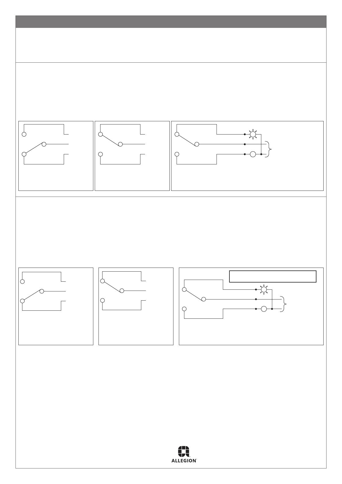
DSM (Door Status Switch)
The DSM provides a signal to indicate whether door is open or closed. The lock’s mounting instructions should be followed closely to
ensure reliable performance. DSM provides a signal via a set of form “C” dry contacts rated 100mA, resistive at 24VDC. These
contacts, which are labeled in an open door condition are accessed by three (3) wires:
White - N.O. (Normally Open)
Black - C (Common)
Red - N.C. (Normally Closed).
When the door closes, black and white wire contacts close and black and red wire contacts open. See Fig. 4, Fig. 5 and Fig. 6.
N.O. (WHITE)
C (BLACK)
N.C. (RED)
Fig. 4: Contact conguration
when door is open
N.O. (WHITE)
C (BLACK)
N.C. (RED)
Fig. 5: Contact conguration
when door is closed
G
R
N.O. (WHITE)
C (BLACK)
N.C. (RED)
To low voltage power
source compatible
lamp voltage
requirements.
Fig. 6: Wiring example of contacts used to switch external
indicators (not included). Shown door closed. Green LED
lit.
MBS (Magnetic Bond Sensor)

materials in magnetic gap, and damaged or dirty magnet and/or armature surfaces. The MBS option provides a signal via a set of
form “C” dry contacts rated 1A @ 30VDC resistive load maximum. Dry contacts, which are labeled in a deenergized/no bond
condition are accessed by three (3) wires:
Green - N.O. (Normally Open)
Brown - C (Common)
Blue - N.C. (Normally Closed)
Once the lock is energized with magnet and armature properly bonded, C and N.O. contacts close and C and N.C. contacts open.
See Fig. 7, Fig. 8 and Fig. 9.
N.O. (GREEN)
C (BROWN)
N.C. (BLUE)
Contact configuration
when insufficient or
no bond exists
Fig. 7: Contact conguration
when insucient or no
bond exists
N.O. (GREEN)
C (BROWN)
N.C. (BLUE)
Contact configuration
when sufficient bond exists
Fig. 8: Contact conguration
when sucient bond exists
N.O. (GREEN)
C (BROWN)
N.C. (BLUE)
Wiring example of contacts used to switch
external indicators (not included).
Shown door closed. Green LED lit.
R
GTo low voltage
power source
compatible with
lamp voltage
requirements.
Green - Lit when sufficient bond exists
Red - Lit when insufficient bond exists
Fig. 9: Wiring example of contacts used to switch
external indicators (not included). Shown door closed.
Green LED lit.
varies
varies
FRONT
Additional Notes: Revision History Revision Description:
j > Revised artwork
1. Final folded size may vary to t in box. D E F G H j
009827 013686 013687 23854 046613 081608
Material
White Paper
Edited By Approved By EC Number Release Date
M. Sasso D. Toppins 081608 08-12-19
Notes
1. printed two sides
2. printed black
3. stapled in top left corner
4. tolerance ± .06
5. printed in country may vary
6. drawings not to scale
Title
SHEET, INSTALLATION, 320M
Creation Date
11-12-2012
Number
30020
Revision
j
Created By
P. Bockelman Activity
3899 Hancock Expwy
Security, CO 80911 © Allegion 2019Software: InDesign CS6
A4 (8.270)
A4
(11.693)
BEGINNING SHEET FOLDED SHEET
FRONT
STAPLE
  • Page 1 1
  • Page 2 2
  • Page 3 3
  • Page 4 4
  • Page 5 5
  • Page 6 6
  • Page 7 7

Schlage 320 Series User manual

Type
User manual

Schlage 320 Series is a medium-security electromagnetic lock designed for sliding doors. With no moving parts, it requires minimal maintenance and meets security and life safety requirements. Its versatility allows for field selection of 12VDC or 24VDC operation, making it suitable for various applications. The 320 Series boasts a rated holding force of 550lbs at 24VDC, providing enhanced security.

Ask a question and I''ll find the answer in the document

Finding information in a document is now easier with AI