Mode d’emploi Série RRC à puissance et TCP sélectionnables
Plafonniers MaxLite pour l’architecture commerciale
© Droits d’auteur 2021. MaxLite, Inc. Tous droits réservés.
12
Y
ork Av
e,
W
est Caldwell, NJ 07006
Tél:
973-244-7300 F
ax:
973-244-7333 Email:
inf
[email protected]Page: 1
RÉV: 12/01/21
®
L’image est pour des fins d’illustration
seulement. Votre modèle peut être différent.
AVERTISSEMENT: RISQUE DE CHOC ÉLECTRIQUE
• Débranchez l’alimentation électrique au fusible ou au disjoncteur avant de connecter le luminaire
à la source d’alimentation.
• Débranchez l’alimentation lorsque vous effectuez des travaux d’entretien.
• Vérifiez si la valeur de la tension d’alimentation est correcte en la comparant aux informations
dans le tableau sur l’étiquette du luminaire.
• Réalisez toutes les connexions électriques et de terre en conformité avec le code électrique national
et les éventuelles exigences locales applicables du code.
• Toutes les connexions électriques seront terminées avec des connecteurs pour fils approuvés UL.
AVERTISSEMENT – RISQUE D’INCENDIE OU DE CHOC ÉLECTRIQUE. L’INSTALLATION DE CE KIT DE
MODERNISATION SERA RÉALISÉE PAR UNE PERSONNE FAMILIARISÉE AVEC LA CONSTRUCTION ET
LE FONCTIONNEMENT DU SYSTÈME ÉLECTRIQUE DU LUMINAIRE ET AVEC LES RISQUES POSSIBLES.
L’INSTALLATION NE SERA PAS EFFECTUÉE PAR LES PERSONNES SANS QUALIFICATION. CONTACTEZ
UN ÉLECTRICIEN QUALIFIÉ.
AVERTISSEMENT – RISQUE D’INCENDIE OU DE CHOC ÉLECTRIQUE. INSTALLEZ CE KIT UNIQUEMENT
DANS LE LUMINAIRE QUI A LES CARACTÉRISTIQUES CONSTRUCTIVES ET LES DIMENSIONS
AFFICHÉES DANS LES IMAGES ET / OU LES SCHÉMAS SI LA TENSION NOMINALE D’ENTRÉE DU KIT
DE MODERNISATION NE DÉPASSE PAS LA TENSION NOMINALE D’ENTRÉE DU LUMINAIRE.
NE PAS RÉALISER OU MODIFIER DE TROUS DANS UNE ENCEINTE DE CÂBLAGE OU DE COMPOSANTS
ÉLECTRIQUES PENDANT L’INSTALLATION DE CE KIT.
AVERTISSEMENT – POUR PRÉVENIR LES DOMMAGES DE CÂBLAGE OU L’ABRASION, NE PAS
EXPOSER LE CÂBLAGE AUX BORDURES DE TÔLE OU AUX AUTRES OBJETS TRANCHANTS.
LE KIT DE MODERNISATION EST ACCEPTÉ COMME COMPOSANT D’UN LUMINAIRE LORSQUE
L’ADAPTABILITÉ DE LA COMBINAISON SERA ÉTABLIE PAR LES AUTORITÉS AYANT JURIDICTION.
LE PRODUIT SERA INSTALLÉ PAR UN ÉLECTRICIEN QUALIFIÉ EN CONFORMITÉ AVEC LES CODES
ÉLECTRIQUES APPLICABLES ET PERTINENTS. LE GUIDE D’INSTALLATION NE REMPLACE PAS LES
RÉGLEMENTATIONS LOCALES OU NATIONALES CONCERNANT LES INSTALLATIONS ÉLECTRIQUES.
PRÉCAUTION:
• Ne remplacer aucun accessoire, afin de prévenir le risque de chute, choc électrique ou incendie. Etc.
• Ne pas toucher à la lampe lorsqu’elle est utilisée.
• Toujours débrancher l’alimentation principale. Attendre de 5 à 10 minutes avant de remplacer la lampe,
afin de lui permettre de refroidir.
• Les lampes ne seront utilisées qu’avec leur enveloppe de protection!
PRÉCAUTION: RISQUE DE BLESSURE
• Portez des gants et des lunettes de sécurité lors de l’enlèvement du luminaire de l’emballage,
l’installation, les travaux de réparation ou d’entretien.
• Évitez l’exposition directe des yeux à la source de lumière si le luminaire est allumé.
• Comptabilisez les composants de dimensions réduites et éliminez l’emballage, parce qu’il peut
représenter un risque pour les enfants.
PRÉCAUTION: RISQUE D’INCENDIE
• Gardez les matériaux combustibles et les autres
matériaux qui peuvent brûler à distance du luminaire.
• CONDUCTEURS D’ALIMENTATION MIN 75°C.
Modèles: Série RRC
Tension d’entrée nominale: 120-277V, 50/60hz, variateur 0-10V
Température de fonctionnement: -4°F à 104°F (-20C° à 40°C)
Convient aux endroits humides
Consignes générales de sécurité
• Avant l’installation, la réparation ou la réalisation des opérations ordinaires d’entretien de cet équipement,
suivez ces précautions générales.
•Pour réduire le risque de décès, de blessure corporelle ou de dommage matériel provoqué par incendie,
choc électrique, chute de pièces, coupures / abrasions et autres risques, lisez tous les avertissements et les
instructions qui accompagnent l’emballage du luminaire et toutes les étiquettes du luminaire.
•L’installation commerciale, la réparation et l’entretien des luminaires seront effectués par un électricien
qualifié et autorisé.
•NE PAS INSTALLER DE PRODUITS ENDOMMAGÉS!
•Ce luminaire a été conçu pour être connecté à une boîte de jonction homologuée UL, correctement
installée et reliée à la terre. Liste d’emballage du moteur
d’éclairage
Composants compris:
•1 pièce - Moteur d’éclairage LED
•1 pièce - Manuel d’instructions
Liste d’emballage du kit réflecteur
Composants compris:
•1 pièce - Kit réflecteur
•1 pièce - Manuel d’instructions
•1 pièce - Gabarit de découpe pour
le plafond
DŽƚĞƵƌƐ
Ě͛ĠĐůĂŝƌĂŐĞ&ZĠĨůĞĐƚĞƵƌ ,ĂƵƚĞƵƌĚƵ
ůƵŵŝŶĂŝƌĞ;Ϳ &
ϭϬĐŵͬϰ͟
ϭϱ͕ϮϰĐŵͬϲ͟
ϮϬ͕ϯϮĐŵͬϴ͟
Ϯϰ͕ϭϯĐŵͬϵ͕ϱ͟
ϭϱ͕ϮϰĐŵͬϲ͟
ϮϬ͕ϯϮĐŵͬϴ͟
Ϯϰ͕ϭϯĐŵͬϵ͕ϱ͟
ϲ͕ϰϱĐŵͬϮ͕ϱϰ͟
ϳ͕ϲϳĐŵͬϯ͕ϬϮ͟
ϵ͕ϳϬĐŵͬϯ͕ϴϮ͟
ϭϬ͕ϳϵĐŵͬϰ͕Ϯϱ͟
ϳ͕ϲϵĐŵͬϯ͕Ϭϯ͟
ϵ͕ϳϮĐŵͬϯ͕ϴϯ͟
ϭϬ͕ϳϵĐŵͬϰ͕Ϯϱ͟
ϭϬ͕ϱϰĐŵͬϰ͕ϭϱ
ϭϰ͕ϯϳĐŵͬϱ͕ϲϲ͟
ϭϴ͕ϰϲĐŵͬϳ͕Ϯϳ͟
ϮϬ͕ϴϱĐŵͬϴ͕Ϯϭ͟
ϭϰ͕ϰϬĐŵͬϱ͕ϲϳ͟
ϭϴ͕ϰϵĐŵͬϳ͕Ϯϴ͟
ϮϬ͕ϵϬĐŵͬϴ͕Ϯϯ͟
//01(-023
//01(-4023
//01(#023
//01'-4023
//01'#023
,ĂƵƚĞƵƌĚƵ
ƌĠĨůĞĐƚĞƵƌ;Ϳ
ŝĂŵğƚƌĞ
ŝŶƚĠƌŝĞƵƌ;Ϳ
ŝĂŵğƚƌĞ
ĞdžƚĠƌŝĞƵƌ;Ϳ
ĠĐŽƵƉĞƐ
;ĐŵͬƉŽͿ
ϭϯ͕ϲϲĐŵͬϱ͕ϯϴ͟
ϭϰ͕ϵϬĐŵͬϱ͕ϴϳ͟
ϭϲ͕ϵϰĐŵͬϲ͕ϲϳ͟
ϭϴ͕ϬϯĐŵͬϳ͕ϭ͟
ϭϱ͕ϭϯĐŵͬϱ͕ϵϲ͟
ϭϳ͕ϭϳĐŵͬϲ͕ϳϲ͟
ϭϴ͕ϮϲĐŵͬϳ͕ϭϵ͟
ϭϳ͕ϰϮĐŵͬϲ͕ϴϲ͟
Ϯϭ͕ϰϴĐŵͬϴ͕ϰϲ͟
Ϯϲ͕ϮϭĐŵͬϭϬ͕ϯϮ͟
ϯϬ͕ϬϮĐŵͬϭϭ͕ϴϮ͟
Ϯϭ͕ϰϭĐŵͬϴ͕ϰϯ͟
Ϯϲ͕ϮϯĐŵͬϭϬ͕ϯϯ͟
ϯϬ͕ϬϮĐŵͬϭϭ͕ϴϮ͟
Tϭϭ͕ϵϴͲϭϯ͕ϴϲĐŵͬϰ͕ϳϮͲϱ͕ϰϲ͟
TϭϲͲϭϳ͕ϴϬĐŵͬϲ͕ϯͲϳ͕Ϭϭ͟
Tϭϵ͕ϵϴͲϮϮ͕ϭϵĐŵͬϳ͕ϴϳͲϴ͕ϳϰ͟
TϮϭ͕ϵϵͲϮϱ͕Ϯϵͬϴ͕ϲϲͲϵ͕ϵϲ͟
TϭϲͲϭϳ͕ϴϬĐŵͬϲ͕ϯͲϳ͕Ϭϭ͟
Tϭϵ͕ϵϴͲϮϮ͕ϭϵĐŵͬϳ͕ϴϳͲϴ͕ϳϰ͟
TϮϭ͕ϵϵͲϮϱ͕Ϯϵͬϴ͕ϲϲͲϵ͕ϵϲ͟
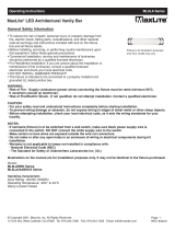
Gants Lunettes
de sécurité Échelle
Serre-fils
Coupe-fils Pince à
dénuder
Outils nécessaires (non fournis)