Page is loading ...

I
WMC252-1W-1T-300
User Manual
P/N 1073055 • REV A • ISS 15OCT15

II
Copyright
© 2015 United Technologies Corporation
Interlogix is part of UTC Building & Industrial Syste
ms, Inc. a unit of United
Technologies Corporation.
All rights reserved.
Trademarks and
patents
The WMC252 Series name and logo are trademarks of United Technologies.
Other trade names used in this document may be trademarks or registered
trademarks of
the manufacturers or vendors of the respective products.
Manufacturer
Interlogix
3211 Progress Drive, Lincolnton, NC 28092 USA
Authorized EU manufacturing representative:
UTC Climate Controls & Security B.V.,
Kelvinstraat
7, 6003 DH Weert, Netherlands
Intended use
Use this product only for the purpose it was designed for; refer to the data sheet
and user documentation for details. For the latest product information, contact
your local supplier or visit us online at www.in
terlogix.com.
Certification
ACMA compliance
Notice!
This is a Class B product. In a domestic environment this product may
cause radio interference in which case the user may be required to take
adequate measures.
European Union
directives
2004/108/EC (EMC Directive):
Hereby, UTC Building & Industrial Systems, Inc.
declares that this device is in compliance with the essential requirements and
other relevant provisions of Directive 2004/108/EC.
Federal Communication Commission Interference Statement
This equipment has been tested and found to comply with the limits for a Class B digital device,
pursuant to part 15 of the FCC Rules. These limits are designed to provide reasonable
protection against harmful interference when the equipment is operated in a commercial
environment. This equipment generates, uses, and can radiate radio frequency energy and, if not
installed and used in accordance with the instruction manual, may cause harmful interference to
radio communications. Operation of this equipment in a residential area is likely to cause harmful
interference in which case the user will be required to correct the interference at his/her own
expense. Any changes or modifications not expressly approved by UTC could void the user’s
authority to operate this equipment under the rules and regulations of the FCC.
FCC Caution:
To assure continued compliance, (for example, use only shielded interface cables when connecting
to computer or peripheral devices) any changes or modifications not expressly approved by the party
responsible for compliance could void the user’s authority to operate the equipment.
This device complies with Part 15 of the FCC Rules. Operation is subject to the following two
conditions:
(1) This device may not cause harmful interference
(2) This device must accept any interference received, including interference that may cause
undesired operation.

III
Federal Communication Commission (FCC) Radiation Exposure Statement
This equipment complies with FCC radiation exposure set forth for an uncontrolled environment. In
order to avoid the possibility of exceeding the FCC radio frequency exposure limits, human proximity
to the antenna shall not be less than 20 cm (8 inches) during normal operation.
CAUTION: Changes or modifications not expressly approved by UTC for compliance could void the
user’s authority to operate the equipment.
CE Mark Warning
This is a Class B product. In a domestic environment, this product may cause radio interference, in
which case the user may be required to take adequate measures.
Energy Saving Note of the Device
This power required device does not support Standby mode operation. For energy saving, please
remove the DC-plug to disconnect the device from the power circuit. Without removing the DC-plug,
the device still consumes power from the power circuit. In view of Saving the Energy, it is strongly
suggested to remove the DC-plug for the device if this device is not intended to be active.
Canadian Compliance
This Class B digital apparatus meets all requirements of the Canadian Interference Causing
Equipment Regulations. Cet appareil numérique de la classe B respects toutes les exigences du
Règlement sur le matériel brouilleur du Canada.
Canada - Industry Canada (IC)
The wireless radio of this device complies with RSS 247 and RSS 102 of Industry Canada.
This Class B digital device complies with Canadian ICES-003 (NMB-003).
Cet appareil numérique de la classe B respects toutes les exigences du Règlement sur le matériel
brouilleur du Canada.
This device complies with Industry Canada’s licence-exempt RSSs. Operation is subject to the
following two conditions:
(1) This device may not cause interference; and
(2) This device must accept any interference, including interference that may cause undesired
operation of the device.
Le présent appareil est conforme aux CNR d'Industrie Canada applicables aux appareils radio
exempts de licence. L'exploitation est autorisée aux deux conditions suivantes :
(1) l'appareil ne doit pas produire de brouillage, et
(2) l'utilisateur de l'appareil doit accepter tout brouillage radioélectrique subi, même si le brouillage est
susceptible d'en compromettre le fonctionnement.
WMC252-1W-1T-300 complies with IC requirements, IC: 20201-WMC252300.

IV
This radio transmitter (IC: 20201-WMC252300) has been approved by Industry Canada to operate with
the antenna types listed below with the maximum permissible gain indicated. Antenna types not
included in this list, having a gain greater than the maximum gain indicated for that type, are strictly
prohibited for use with this device.
Built-in 14dBi Dual-Polarization Antenna
Le présent émetteur radio (IC: 20201-WMC252300) a été approuvé par Industrie Canada pour
fonctionner avec les types d'antenne énumérés ci-dessous et ayant un gain admissible maximal et
l'impédance requise pour chaque type d'antenne. Les types d'antenne non inclus dans cette liste, ou
dont le gain est supérieur au gain maximal indiqué, sont strictement interdits pour l'exploitation de
l'émetteur.
Intégré 14dBi antenne double polarisation
LE-LAN devices shall contain instructions related to the restrictions mentioned in the above sections,
namely that:
1. the device for operation in the band 5150–5250 MHz is only for indoor use to reduce the
potential for harmful interference to co-channel mobile satellite systems;
2. for devices with detachable antenna(s), the maximum antenna gain permitted for devices in the
bands 5250-5350 MHz and 5470-5725 MHz shall be such that the equipment still complies with
the e.i.r.p. limit;
3. for devices with detachable antenna(s), the maximum antenna gain permitted for devices in the
band 5725-5850 MHz shall be such that the equipment still complies with the e.i.r.p. limits
specified for point-to-point and non-point-to-point operation as appropriate; and
4. the worst-case tilt angle(s) necessary to remain compliant with the e.i.r.p. elevation mask
requirement set forth in Section 6.2.2(3)
of RSS-247 shall be clearly indicated.
The maximum conducted output power shall not exceed 250 mW or 11 + 10 log
10
B, dBm, whichever is
less. The power spectral density shall not exceed 11 dBm in any 1.0 MHz band.
The maximum e.i.r.p. shall not exceed 1.0 W or 17 + 10 log
10
B, dBm, whichever is less. B is the 99%
emission bandwidth in megahertz. Note that devices with a maximum e.i.r.p. greater than 500 mW shall
implement TPC in order to have the capability to operate at least 6 dB below the maximum permitted
e.i.r.p. of 1 W.
2) Unwanted emission limits
i) For devices with both operating frequencies and channel bandwidths contained within the band
5250-5350 MHz, the device shall comply with the following:
a. All emissions outside the band 5250-5350 MHz shall not exceed -27 dBm/MHz e.i.r.p. if the
equipment is intended for outdoor use; or
b. All emissions outside the band 5150-5350 MHz shall not exceed -27 dBm/MHz e.i.r.p. and any
emissions within the band 5150-5250 MHz shall meet the power spectral density limits
of Section 6.2.1
of RSS-247. The device shall be labelled “for indoor use only.”

V
ii) For devices with operating frequencies in the band 5250-5350 MHz but having a channel bandwidth
that overlaps the band 5150-5250 MHz, the devices’ unwanted emission shall not exceed
-27 dBm/MHz e.i.r.p. outside the band 5150-5350 MHz and its power shall comply with the spectral
power density for operation within the band 5150-5250 MHz. The device shall be labelled “for indoor
use only.”
3) Additional requirements
In addition to the above requirements, devices operating in the band 5250-5350 MHz with a maximum
e.i.r.p. greater than 200 mW shall comply with the following e.i.r.p. at different elevations, where θ is the
angle above the local horizontal plane (of the Earth) as shown below:
1. -13 dBW/MHz for 0° ≤ θ < 8°
2. -13 − 0.716 (θ-8) dBW/MHz for 8° ≤ θ < 40°
3. -35.9 − 1.22 (θ-40) dBW/MHz for 40° ≤ θ ≤ 45°
4. -42 dBW/MHz for θ > 45°
The measurement procedure defined in Annex A
of RSS-247 shall be used to verify the compliance to
the e.i.r.p. at different elevations.
Users should also be advised that high-power radars are allocated as primary users (i.e. priority users)
of the bands 5250-5350 MHz and 5650-5850 MHz and that these radars could cause interference
and/or damage to LE-LAN devices.
No part of this publication may be reproduced in any form or by any means or used to make any
derivative work (such as translation, transformation or adaptation) without written permission from UTC
Fire and Security.
UTC, reserves the right to revise this publication and to make changes in content from time to time
without obligation on the part of UTC to provide notification of such revision or change. UTC provides
this guide without warranty of any kind, implied or expressed, including, but not limited to, the implied
warranties of merchantability and fitness for a particular purpose. UTC may make improvements or
changes in the product(s) described in this manual at any time.
CAUTION: TO ENSURE REGULATORY COMPLIANCE, USE ONLY THE PROVIDED POWER AND
INTERFACE CABLES.
CAUTION: DO NOT OPEN THE UNIT. DO NOT PERFORM ANY SERVICING OTHER THAN THAT
CONTAINED IN THE INSTALLATION AND TROUBLESHOOTING INSTRUCTIONS. REFER ALL
SERVICING TO QUALIFIED SERVICE PERSONNEL.
R&TTE Compliance Statement
This equipment complies with all the requirements of DIRECTIVE 1999/5/CE OF THE EUROPEAN
PARLIAMENT AND THE COUNCIL OF 9 March 1999 on radio equipment and telecommunication
terminal Equipment and the mutual recognition of their conformity (R&TTE). The R&TTE Directive
repeals and replaces in the directive 98/13/EEC (Telecommunications Terminal Equipment and
Satellite Earth Station Equipment) as of April 8, 2000.

VI
Safety
This equipment is designed with the utmost care for the safety of those who install and use it.
However, special attention must be paid to the dangers of electric shock and static electricity when
working with electrical equipment. All guidelines of this and of the computer manufacture must
therefore be allowed at all times to ensure the safe use of the equipment.
Wireless LAN and your Health
The WMC252-1W-1T-300 like other radio devices, emits radio frequency electromagnetic energy, but
operates within the guidelines found in radio frequency safety standards and recommendations.
Restrictions on Use of Wireless Devices
In some situations or environments, the use of wireless devices may be restricted by the proprietor of
the building or responsible representatives of the organization. For example, these situations may
include:
. Using wireless equipment in any environment where the risk of interference to other devices or
services is perceived or identified as harmful.
If you are uncertain of the applicable policy for the use of wireless equipment in a specific organization
or environment, you are encouraged to ask for authorization to use the device prior to turning on the
equipment.
The manufacturer is not responsible for any radio or television interference caused by unauthorized
modification of the devices included with this product, or the substitution or attachment of connecting
cables and equipment other than specified by the manufacturer. Correction of interference caused by
such unauthorized modification, substitution, or attachment is the responsibility of the user.
The manufacturer and its authorized resellers or distributors are not liable for any damage or violation
of government regulations that may arise from failing to comply with these guideline documentation
that comes with the product.
Postpone router installation until there is no risk of thunderstorm or lightning activity in the area.
Do not overload outlets or extension cords, as this can result in a risk of fire or electric shock.
Overloaded AC outlets, extension cords, frayed power cords, damaged or cracked wire insulation, and
broken plugs are dangerous. They may result in a shock or fire hazard.
Route power supply cords so that they are not likely to be walked on or pinched by items placed upon
or against them. Pay particular attention to cords where they are attached to plugs and convenience
receptacles, and examine the point where they exit from the product.
Place this equipment in a location that is close enough to an electrical outlet to accommodate the
length of the power cord.
Place this equipment on a stable surface.
When using this device, basic safety precautions should always be followed to reduce the risk of fire,
electric shock and injury to persons, including the following:

VII
. Read all of the instructions {listed here and/or in the user manual} before you operate this equipment.
Give particular attention to all safety precautions.
Retain the instructions for future reference.
. Comply with all warning and caution statements in the instructions. Observe all warning and caution
symbols that are affixed to this equipment.
. Comply with all instructions that accompany this equipment.
. Avoid using this product during an electrical storm. There may be a risk of electric shock from
lightning. For added protection for this product during a lightning storm, or when it is left unattended
and unused for long periods of time, unplug it from the wall outlet, and disconnect the cable system.
This will prevent damage to the product due to lightning and power surges. We also recommend the
use of ESP300 20Kv protection on the input at the switch or network.
. Operate this product only from the type of power source indicated on the product’s marking label. If
you are not sure of the type of power supplied to your home, consult your dealer or local power
company.
. Upon completion of any service or repairs to this product, ask the service technician to perform safety
checks to determine that the product is in safe operating condition.
It is recommended that the customer install an AC surge protector in the AC outlet to which this device
is connected. This is to avoid damaging the equipment by local lightning strikes and other electrical
surges.
Different types of cord sets may be used for connections to the main supply circuit. Use only a main
line cord that complies with all applicable product safety requirements of the country of use. Installation
of this product must be in accordance with national wiring codes.
Place unit to allow for easy access when disconnecting the power cord/adapter of the device from the
AC wall outlet.
Wipe the unit with a clean, dry cloth. Never use cleaning fluid or similar chemicals. Do not spray
cleaners directly on the unit or use forced air to remove dust.
This product was qualified under test conditions that included the use of the supplied cables between
system components. To be in compliance with regulations, the user must use these cables and install
them properly. Connect the unit to a grounding type AC wall outlet using the power adapter supplied
with the unit.
Do not cover the device, or block the airflow to the device with any other objects. Keep the device away
from excessive heat and humidity and keep the device free from vibration and dust.
Installation must at all times conform to local regulations

VIII
National Restrictions
This device is intended for home and office use in all EU countries (and other countries following the
EU directive 1999/5/EC) without any limitation except for the countries mentioned below:
Country Restriction Reasons/remarks
Bulgaria None
General authorization required for outdoor
use and public service
France
Outdoor use; limited to 10
mW e.i.r.p. within the
band 2454-2483.5 MHz
Military Radiolocation use. Reframing of the 2.4
GHz band has been ongoing in recent years to
allow current relaxed regulation. Full
implementation planned 2012
Italy None
If used outside of own premises, general
authorization is required
Luxembourg None
General authorization required for network and
service supply(not for spectrum)
Norway Implemented
This subsection does not apply for the
geographical area within a radius of 20 km from the
centre of Ny-Ålesund
Russian
Federation
None Only for indoor applications
Note: Please don’t use the product outdoors in France.
WEEE regulation
To avoid the potential effects on the environment and human health as a result of the
presence of hazardous substances in electrical and electronic equipment, end users of
electrical and electronic equipment should understand the meaning of the crossed-out
wheeled bin symbol. Do not dispose of WEEE as unsorted municipal waste and have to
collect such WEEE separately.
Contact Information
For contact information, se
e www.interlogix.com
or
www.utcfssecurityproducts.eu.

IX
CONTENTS
Chapter 1.Product Introduction ......................................................................................................... 13
1.1 Package Contents ............................................................................................................. 13
1.2 Product Description .......................................................................................................... 14
1.3 Product Features ............................................................................................................... 15
1.4 Product Specifications ..................................................................................................... 16
Chapter 2.Hardware Installation ........................................................................................................ 19
2.1 Hardware Description ....................................................................................................... 19
2.1.1 The Bottom Panel – Port ........................................................................................ 20
Chapter 3.Connecting to the AP ........................................................................................................ 23
3.1 Preparation before Installation ........................................................................................ 23
3.1.1 Professional Installation Required .......................................................................... 23
3.1.2 Safety Precautions .................................................................................................. 23
3.2 Installation Precautions .................................................................................................... 23
3.3 Installing the AP ................................................................................................................ 25
3.4 Standard Pole Mounting ................................................................................................... 26
Chapter 4.Quick Installation Guide ................................................................................................... 27
4.1 Manual Network Setup - TCP/IP Configuration .............................................................. 27
4.1.1 Configuring the IP Address Manually ..................................................................... 27
4.2 Starting Setup in the Web UI ............................................................................................ 30
Chapter 5.Configuring the AP ............................................................................................................ 33
5.1 Operation Mode ................................................................................................................. 33
5.1.1 Access Point ........................................................................................................... 33
5.1.2 Client ....................................................................................................................... 35
5.1.3 WDS AP .................................................................................................................. 36
5.1.4 WDS Client ............................................................................................................. 37
5.1.5 AP Router ............................................................................................................... 38
5.1.6 Wireless ISP ........................................................................................................... 39
5.1.7 Security Setting ....................................................................................................... 40
5.1.8 Advanced Settings .................................................................................................. 45
5.1.9 Access Control ........................................................................................................ 48
5.1.10 WAN Port Settings .................................................................................................. 49
5.1.11 Dynamic DNS Settings ........................................................................................... 51
5.1.12 Remote Management ............................................................................................. 54
5.1.13 DHCP Server Settings ............................................................................................ 54

X
5.1.14 DMZ Settings .......................................................................................................... 55
5.1.15 Virtual Server Settings ............................................................................................ 56
5.1.16 IP Filtering Settings ................................................................................................. 56
5.1.17 Port Filtering Settings ............................................................................................. 57
5.1.18 MAC Filtering Settings ............................................................................................ 58
5.1.19 Bandwidth Control .................................................................................................. 58
5.1.20 SNMP...................................................................................................................... 59
5.2 System Configuration ....................................................................................................... 60
5.2.1 Default IP Settings .................................................................................................. 60
5.2.2 Time Settings .......................................................................................................... 61
5.2.3 Password Settings .................................................................................................. 61
5.2.4 System Management .............................................................................................. 62
5.2.5 Ping Watchdog ........................................................................................................ 63
5.2.6 Firmware Upgrade .................................................................................................. 64
5.2.7 Configuration Save and Restore ............................................................................ 64
5.2.8 Factory Default ....................................................................................................... 65
5.2.9 Reboot System ....................................................................................................... 65
5.2.10 Schedule Reboot .................................................................................................... 65
5.3 Tools ................................................................................................................................... 68
5.3.1 Network Ping .......................................................................................................... 68
5.3.2 Network Traceroute ................................................................................................ 68
5.4 Device Status ..................................................................................................................... 70
5.4.1 Device Information .................................................................................................. 70
5.4.2 Wireless Information ............................................................................................... 71
5.4.3 LAN Information ...................................................................................................... 72
5.4.4 Wireless Client Table .............................................................................................. 73
5.4.5 System Log ............................................................................................................. 73
5.5 Logout ................................................................................................................................ 75
Appendix A: Troubleshooting ............................................................................................................ 76
Appendix B: FAQ ................................................................................................................................. 78
Q1: How to set up the AP Client Connection ........................................................................... 78
Q2: How to set up the WDS Connection .................................................................................. 86

XI
FIGURES
FIGURE 2-1 THREE-WAY VIEW .................................................................................................................. 19
FIGURE 2-2 LED ..................................................................................................................................... 20
FIGURE 2-3 BOTTOM PANEL ..................................................................................................................... 21
FIGURE 2-4 POE INJECTOR ...................................................................................................................... 21
FIGURE 3-1 CONNECT THE ANTENNA ........................................................................................................ 25
FIGURE 3-2 CONNECT THE ETHERNET CABLE ............................................................................................ 25
FIGURE 3-3 CONNECT THE POE INJECTOR ................................................................................................ 26
FIGURE 3-4 POLE MOUNTING ................................................................................................................... 26
FIGURE 4-1 TCP/IP SETTING ................................................................................................................... 28
FIGURE 4-2 WINDOWS START MENU ........................................................................................................ 29
FIGURE 4-3 SUCCESSFUL RESULT OF PING COMMAND ............................................................................... 29
FIGURE 4-4 FAILED RESULT OF PING COMMAND......................................................................................... 30
FIGURE 4-5 LOGIN BY DEFAULT IP ADDRESS .............................................................................................. 30
FIGURE 4-6 LOGIN WINDOW ..................................................................................................................... 31
FIGURE 4-7 WMC252-300 WEB UI SCREENSHOT .................................................................................... 31
FIGURE 4-8 CHOOSE OPERATION MODE ................................................................................................... 32
FIGURE 4-9 CONFIGURE WIRELESS SETTINGS .......................................................................................... 32
FIGURE 5-1 MAIN MENU .......................................................................................................................... 33
FIGURE 5-2 OPERATION MODE ................................................................................................................. 33
FIGURE 5-3 BASIC SETTINGS - AP ............................................................................................................ 34
FIGURE 5-4 BASIC SETTINGS - CLIENT ...................................................................................................... 35
FIGURE 5-5 BASIC SETTINGS – WDS AP .................................................................................................. 37
FIGURE 5-6 BASIC SETTINGS – WDS CLIENT............................................................................................ 37
FIGURE 5-7 BASIC SETTINGS – AP ROUTER ............................................................................................. 38
FIGURE 5-8 BASIC SETTINGS – WISP ...................................................................................................... 39
FIGURE 5-9 SECURITY SETTINGS ............................................................................................................. 40
FIGURE 5-10 SECURITY SETTINGS – WEP ............................................................................................... 41
FIGURE 5-11 SECURITY SETTINGS – WPA PERSONAL ............................................................................... 41
FIGURE 5-12 SECURITY SETTINGS – WPA ENTERPRISE ............................................................................ 42
FIGURE 5-13 SECURITY SETTINGS – WPA2 PERSONAL ............................................................................. 43
FIGURE 5-14 SECURITY SETTINGS – WPA2 ENTERPRISE .......................................................................... 43
FIGURE 5-15 SECURITY SETTINGS – WPA-MIXED PERSONAL .................................................................... 44
FIGURE 5-16 SECURITY SETTINGS – WPA-MIXED ENTERPRISE ................................................................. 44
FIGURE 5-17 ADVANCED SETTINGS .......................................................................................................... 45
FIGURE 5-18 WMM CONFIGURATION ....................................................................................................... 46
FIGURE 5-19 ACCESS CONTROL .............................................................................................................. 48
FIGURE 5-20 WAN PORT SETTINGS – DHCP ........................................................................................... 49
FIGURE 5-21 WAN PORT SETTINGS – STATIC IP ....................................................................................... 49
FIGURE 5-22 WAN PORT SETTINGS – PPPOE ......................................................................................... 50

XII
FIGURE 5-23 DYNAMIC DNS SETTINGS .................................................................................................... 51
FIGURE 5-24 REMOTE MANAGEMENT ....................................................................................................... 54
FIGURE 5-25 DHCP SERVER SETTINGS ................................................................................................... 54
FIGURE 5-26 DMZ SETTINGS ................................................................................................................... 55
FIGURE 5-27 VIRTUAL SERVER SETTINGS ................................................................................................. 56
FIGURE 5-28 IP FILTERING SETTINGS ....................................................................................................... 57
FIGURE 5-29 PORT FILTERING SETTINGS .................................................................................................. 57
FIGURE 5-30 MAC FILTERING SETTINGS ................................................................................................... 58
FIGURE 5-31 BANDWIDTH CONTROL SETTINGS ......................................................................................... 58
FIGURE 5-32 SNMP SETTINGS ................................................................................................................ 59
FIGURE 5-33 SYSTEM CONFIGURATION DEFAULT PAGE .............................................................................. 60
FIGURE 5-34 DEFAULT IP SETTINGS ......................................................................................................... 60
FIGURE 5-35 TIME SETTINGS ................................................................................................................... 61
FIGURE 5-36 PASSWORD SETTINGS ......................................................................................................... 62
FIGURE 5-37 SYSTEM MANAGEMENT ........................................................................................................ 62
FIGURE 5-38 PING WATCHDOG ................................................................................................................ 63
FIGURE 5-39 FIRMWARE UPGRADE .......................................................................................................... 64
FIGURE 5-40 CONFIGURATION SAVE AND RESTORE ................................................................................... 64
FIGURE 5-41 FACTORY DEFAULT .............................................................................................................. 65
FIGURE 5-42 REBOOT SYSTEM ................................................................................................................ 65
FIGURE 5-43 SCHEDULE REBOOT ............................................................................................................ 66
FIGURE 5-44 SCHEDULE REBOOT - EXAMPLE ........................................................................................... 67
FIGURE 5-45 NETWORK PING .................................................................................................................. 68
FIGURE 5-46 NETWORK TRACEROUTE ...................................................................................................... 69
FIGURE 5-47 DEVICE STATUS ................................................................................................................... 70
FIGURE 5-48 DEVICE INFORMATION .......................................................................................................... 70
FIGURE 5-49 WIRELESS INFORMATION ..................................................................................................... 71
FIGURE 5-50 LAN INFORMATION .............................................................................................................. 72
FIGURE 5-51 WIRELESS CLIENT TABLE ..................................................................................................... 73
FIGURE 5-52 SYSTEM LOG ...................................................................................................................... 74
FIGURE 5-53 LOGOUT.............................................................................................................................. 75
FIGURE 5-54 RE-LOGIN ........................................................................................................................... 75

-13-
Chapter 1. Product Introduction
1.1 Package Contents
Thank you for choosing IFS WMC252-1W-1T-300. Before installing the AP, please verify the contents inside the
package box.
WMC252-1W-1T-300
Quick Installation Guide
PoE Injector & Power Cord
Plastic Strap x 1
If there is any item missing or damaged, please contact the seller
immediately.

-14-
1.2 Product Description
IFS WMC252-300 Wireless Outdoor Access Point provides a higher transmission speed, higher power and
better performance designed for outdoor wireless application.
Faster Speed and longer Distance
Adopting the IEEE 802.11n advanced 2T2R MIMO technology; the WMC252-300 provides high speed, reliable
wireless network coverage, and incredible improvement in the wireless performance. As an IEEE 802.11a/n
compliant wireless device, the WMC252-300 is able to give stable and efficient wireless performance for long
distance application. Thus, it delivers a data rate of up to 300Mbps three times faster than the normal 802.11a
wireless device. With its adjustable output power up to 500mW, it can extend the coverage of an outdoor area.
Multiple Operation and Wireless Modes
The WMC252-300 supports multiple wireless communication connectivity’s (AP, Client CPE, WDS PtP, WDS
PtMP and WISP), meeting user’s application requirements. It also helps user to easily extend the existing
wireless network.
Advanced Wireless Security
In aspect of security, besides 64/128- bit WEP encryption, the WMC252-300 is integrated with WPA / WPA2,
WPA-PSK / WPA2-PSK and 802.1x authority to secure and protect your wireless LAN. The wireless MAC
filtering and SSID broadcast help to consolidate the wireless network security and prevent unauthorized wireless
connection.
Perfect Solution for Outdoor Environment
The WMC252-300 is perfectly suitable to be installed in outdoor environments. With its IP55 casing protection,
the WMC252-300 can perform normally under rigorous weather conditions including heavy rain and wind. With
the passive Power over Ethernet (PoE) design, the WMC252-300 can be easily installed in the areas where
power outlets are not available. Thus, the WMC252-300 is ideal for outdoor wireless access applications
between buildings on campuses, and in business and rural areas.
Easy Installation and Management
With user-friendly Web UI and step by step Setup Wizard, user can set up a wireless network without any
difficulty.

-15-
1.3 Product Features
Industrial Compliant Wireless LAN & LAN
Compliant with the IEEE 802.11n wireless technology (with data rate of up to 300Mbps)
Backward compatible with 802.11a standard
Equipped with 10/100Mbps RJ45 ports for LAN & WAN; auto MDI/ MDI-X supported
Fixed-network Broadband Router
Supported connection types: Dynamic IP, Static IP, PPPoE
Supports Virtual Server, DMZ for various networking applications
Supports DHCP Server, UPnP, Dynamic DNS
RF Interface Characteristics
Built-in 14dBi Dual-Polarization Antenna
High Output Power Up to 500mW with multiple adjustable transmit power control
Outdoor Environmental Characteristics
IP55 enclosure
Passive Power over Ethernet design
Operating temperature: -20~70°C
Multiple Operation and Wireless Modes
Multiple operation modes: Bridge, WISP
Multiple wireless modes: AP, Client CPE(WISP), WDS PtP, WDS PtMP
Supports multiple SSIDs to allow users to access different networks through a single AP
Supports WMM (Wi-Fi multimedia)
Secure Network Connection
Supports software Wi-Fi Protected Setup (WPS)
Advanced security: 64/128-bit WEP, WPA/WPA2, WPA-PSK/WPA2-PSK(TKIP/AES) and 802.1x
authentication
Supports IP / Protocol-based access control and MAC filtering
Easy Installation and Management
Web-based UI and quick Setup Wizard for easy configuration
SNMP-based management interface
System status monitoring includes DHCP Client, System Log

-16-
1.4 Product Specifications
Product
WMC252-1W-1T-300
300Mbps 802.11a/n Wireless Outdoor CPE
Hardware
Standard Support
IEEE802.11a/n
IEEE 802.3
IEEE 802.3u
IEEE 802.3x
Chipset
Atheros AR9344
Memory
64 Mbytes DDR SDRAM
16 Mbytes Flash
PoE
Passive PoE
Interface
Wireless IEEE802.11a/n, 2T2R
PoE LAN (LAN 1): 1 x 10/100BASE-TX, auto-MDI/MDIX, passive PoE
LAN 2: 1 x 10/100BASE-TX, auto-MDI/MDIX, passive PoE out pass-through
Antenna
Built-in 14dBi Dual-Polarization Antenna
- Horizontal: 30 degrees
- Vertical: 20 degrees
Data Rate
IEEE 802.11a: 6, 9, 12, 18, 24, 36, 48, 54Mbps
IEEE 802.11n (20MHz): up to 150Mbps
IEEE 802.11n (40MHz): up to 300Mbp
Media Access Control
CSMA/CA
Modulation
Transmission/Emission type: OFDM
Data modulation type: OFDM with BPSK, QPSK, 16-QAM, 64-QAM
Frequency Band
5.180GHz ~ 5.825GHz
Operating Channel
5.180GHz
CH36
5.580GHz
CH116
5.200GHz
CH40
5.600GHz
CH120
5.220GHz
CH44
5.620GHz
CH124
5.240GHz
CH48
5.640GHz
CH128
5.260GHz
CH52
5.660GHz
CH132
5.280GHz
CH56
5.680GHz
CH136
5.300GHz
CH60
5.700GHz
CH140
5.320GHz
CH64
5.745GHz
CH149
5.500GHz
CH100
5.765GHz
CH153
5.520GHz
CH104
5.785GHz
CH157
5.540GHz
CH108
5.805GHz
CH161
5.560GHz
CH112
5.825GHz
CH165
*The 24 channels are defined by the theory. The actual application will vary
based on the regulation in different regions and countries.
RF Output Power (dBm)
802.11a: up to 26 ± 1

-17-
802.11n: up to 25 ± 1
Receiver Sensitivity
(dBm)
802.11a: -94dBm
802.11n: -93dBm
Output Power Control 12~27dBm
Power Consumption 12W
Power Requirements
LAN 24VDC, 1A/ Passive PoE
Pin 4,5 VDC+
Pin 7,8 VDC-
Pin 3 Reset
Environment & Certification
Operating Temperature
-20~70°c
Operating Humidity
10~95% non-condensing
IP Level
IP55
Regulatory
CE, FCC, RoHS
Software
LAN
Built-in DHCP server supporting static IP address distribution
Support 802.1d STP (Spanning Tree)
WAN
Static IP
Dynamic IP
PPPoE
Operation Modes
Bridge
WISP
Firewall
NAT firewall with SPI (Stateful Packet Inspection)
Built-in NAT server supporting Virtual Server, and DMZ
Built-in firewall with Port/ IP address/ MAC/ URL filtering
Wireless Modes
AP
Client
WDS PTP
WDS PTMP
WISP
Channel Width
20MHz / 40MHz
Wireless Isolation
Enable it to isolate each connected wireless client so that they
cannot access
mutually.
Encryption Type
64/128-bit WEP, WPA, WPA-PSK, WPA2, WPA2-PSK, 802.1X
Wireless Security
Provides wireless LAN ACL (Access Control List) filtering
Wireless MAC address filtering
Enable/Disable SSID Broadcast
Max. Wireless Clients
25
Max. WDS Peers
8
Max. Wired Clients
60
WMM Supports Wi-Fi multimedia

-18-
QoS Supports Quality of Service for bandwidth control
NTP Network Time Management
Self Healing
Supports Schedule Reboot
Management
Web UI, DHCP Client, Configuration Backup & Restore, Dynamic DNS, SNMP
Diagnostic Tool
System Log, Ping Watchdog

-19-
Chapter 2. Hardware Installation
Please follow the instructions below to connect the WMC252-300 to the existing network devices and your
computers.
2.1 Hardware Description
Dimensions: 127 x 63 x 254 mm (W x D x H)
Appearance
Figure 2-1 Three-way View

-20-
Rear Panel – LED
Figure 2-2 LED
LED Definition
LED State Meaning
Power
On System On
Off System Off
Signal Indicator
On Indicates the wireless signal strength of remote AP
(Client Mode)
Off No remote wireless signal
LAN 1
On Port linked.
Off No link.
LAN 2
On Port linked.
Off No link.
Table 2-1 The LED indication
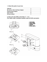
2.1.1 The Bottom Panel – Port
The Bottom panel provides the physical connectors connected to the power adapter and any other network
device. Figure 2-3 shows the bottom panel of the WMC252-300.
/