Page is loading ...

ADDENDUM TO OPERATING INSTRUCTIONS
FLOWSIC500 – Class I, Division 2
Main
FLOWSIC500
Gas flow meter

2 FLOWSIC500 · Addendum to Operating Instructions · 8022943/V1-0/2018-05 · © SICK Engineering GmbH
Document Information
Described Product
Product name: FLOWSIC500
Document ID
Title: Addendum to Operating Instructions
FLOWSIC500 "Class I, Division 2“
Part No.: 8022943
Document ID: 9285023
Version: 1-0
Release: 2018-05
Manufacturer
SICK Engineering GmbH
Bergener Ring 27 · D-01458 Ottendorf-Okrilla · Germany
Phone: +49 35205 52410
Fax: +49 35205 52450
E-mail: [email protected]
Original Documents
The English version 8022943 of this document is an original
document from SICK Engineering GmbH.
SICK Engineering GmbH assumes no liability for the correctness of
an unauthorized translation.
Please contact SICK Engineering GmbH or your local representative
in case of doubt.
Legal Information
Subject to change without notice.
© SICK Engineering GmbH. All rights reserved.
Warning Symbols
Warning Levels / Signal Words
DANGER
Risk or hazardous situation which will result in severe personal
injury or death.
WARNING
Risk or hazardous situation which could result in severe personal
injury or death.
CAUTION
Hazard or unsafe practice which could result in less severe or
minor injuries.
NOTICE
Hazards which could result in property damage
Information Symbols
Hazard (general)
Important technical information for this product
Supplementary information
Link to information in another place

Contents
FLOWSIC500 · Addendum to Operating Instructions · 8022943/V1-0/2018-05 · © SICK Engineering GmbH 3
1 Important Information . . . . . . . . . . . . . . . . . . . . . . . . . . . . . . . . . . . . . . . . . . . . . . . 5
1.1 About this document . . . . . . . . . . . . . . . . . . . . . . . . . . . . . . . . . . . . . . . . . . . . . . . . . . . . . . . . . 6
1.2 For your safety . . . . . . . . . . . . . . . . . . . . . . . . . . . . . . . . . . . . . . . . . . . . . . . . . . . . . . . . . . . . . . 6
2Class I Division 2 . . . . . . . . . . . . . . . . . . . . . . . . . . . . . . . . . . . . . . . . . . . . . . . . . . . . . . 7
2.1 Product identification . . . . . . . . . . . . . . . . . . . . . . . . . . . . . . . . . . . . . . . . . . . . . . . . . . . . . . . . 8
2.2 Operation in potentially explosive atmospheres . . . . . . . . . . . . . . . . . . . . . . . . . . . . . . . . . 9
2.3 Product description . . . . . . . . . . . . . . . . . . . . . . . . . . . . . . . . . . . . . . . . . . . . . . . . . . . . . . . . . 10
2.4 Electrical Installation . . . . . . . . . . . . . . . . . . . . . . . . . . . . . . . . . . . . . . . . . . . . . . . . . . . . . . . . 11
2.4.1 Operating parameters and terminal assignment . . . . . . . . . . . . . . . . . . . . . . . . . . . . . 11
2.5 Annex . . . . . . . . . . . . . . . . . . . . . . . . . . . . . . . . . . . . . . . . . . . . . . . . . . . . . . . . . . . . . . . . . . . . . 14
Contents

Contents
4 FLOWSIC500 · Addendum to Operating Instructions · 8022943/V1-0/2018-05 · © SICK Engineering GmbH


6 FLOWSIC500 · Addendum to Operating Instructions · 8022943/V1-0/2018-05 · © SICK Engineering GmbH
Important Information
1.1
About this document
This document is an addendum to the currently valid Operating Instructions FLOWSIC500
and may only be used in conjunction with them.
This document applies to FLOWSIC500 with Ex classification Class I, Division 2, Groups A,
B, C, and/or D, T4 (see type plate
p. 9, Fig. 3).
Special instructions for FLOWSIC500 in this document overwrite related general informa-
tion in the FLOWSIC500 Operating Instructions
1.2 For your safety
NOTICE:
▸
Read the Operating Instructions carefully before using the FLOWSIC500.
▸
Observe all safety and warning notes!


8 FLOWSIC500 · Addendum to Operating Instructions · 8022943/V1-0/2018-05 · © SICK Engineering GmbH
Class I Division 2
2.1
Product identification
Make sure this document is valid for your FLOWSIC500:
▸
Check the type code, position 20 “Ex certification” on the type plate (→ Fig. 2) of your
FLOWSIC500.
The FLOWSIC500 with Ex certification "4" Class I, Division 2, Groups A, B, C, and/or D, T4 is
described in this document.
Fig. 1 Type code
Fig. 2 Location of type plates
22
-
22 Ex certification
FL5 xx54
23 24 2520 21 22
1 Type plate, metrological parameters (metrology)
2 Type plate, electrical parameters (electronics)
3 Type plate, Pressure Equipment Directive
1
3
Marking according to CSA
2

Class I Division 2
FLOWSIC500 · Addendum to Operating Instructions · 8022943/V1-0/2018-05 · © SICK Engineering GmbH 9
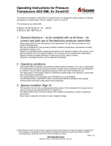
Fig. 3 Type plate electrical parameters (examples)
2.2 Operation in potentially explosive atmospheres
Diameter: 3.445”
Diameter: 3.445”
Max. weight: 40.3lb
(incl. adapter)
Max. weight: 40.3lb
(incl. adapter)
4099990
4099990
Material: Aluminium
Material: Aluminium
FL5-abccdefghijklmnopqr5B4v
FL5-abccdefghijklmnopqr5C4v
Serial No. 10000000
Serial No. 10000000
Part No. 1000000
Part No. 1000000
FLOWSIC500
FLOWSIC500
Power Supply: Class 2/SELV
5.5...28.8 Vdc; max. 100 mA
Powered by Battery pack inside
ext. Power supply not allowed
Cl.I,Div.2,GroupsA,B,CandD,T4
ClassI,Zone2,IICT4Gc
Cl.I,Div.2,GroupsA,B,CandD,T4
ClassI,Zone2,IICT4Gc
CSA 13.2566240
CSA 13.2566240
WARNING-EXPLOSION HAZARD:
Substitution of components may impair suitability
for Class I, Division 2. Do not connect while circuit
is live unless area is known to be nonhazardous.
La substitution de composants peut nuire a la
Class I, Division 2. Ne pas se connecter lorsque
le circuit est sous tension a moins que la zone
ne soit reconnue non dangereuse.
AVERTISSEMENT-RISQUE DÈXPLOSION:
(1) PWR+
(2) Data+
(3) GND
(4) Data-
(1) P WR+
(2) Data+
(3) GND
(4) Data-
(1) PWR+
(2) Data+
(3) GND
(4) Data-
(1) P WR+
(2) Data+
(3) GND
(4) Data-
Sensor
Sensor
Sensor
Sensor
1
1
2
2
4
4
3
3
1
1
2
2
4
4
3
3
Battery-powered version
Externally powered version
The FLOWSIC500 is suitable for use in potentially explosive atmospheres:
Class I, Division 2, Groups A, B, C, and/or D, T4.

10 FLOWSIC500 · Addendum to Operating Instructions · 8022943/V1-0/2018-05 · © SICK Engineering GmbH
Class I Division 2
2.3
Product description
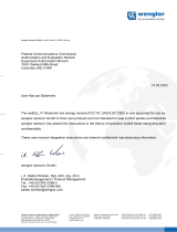
Instead of the two M12 connectors, the Class I, Division 2 version of the FLOWSIC500 is
equipped with with 1/2" NPT thread adapter in order to provide wiring methodes according
to the CEC Part 1.
An additional circuit board is installed in the terminal compartment for the externally pow-
ered meter configuration.
Additional M8 connectors for connection of external pressure and temperature sensors are
optionally available (see Operating Instructions FLOWSIC500, §3.5).
Fig. 4 FLOWSIC500 Class I, Division 2
BAT1
DO3
DO0
+-
RS485
*
P1
P2
T1
T2
SENSORS
DISPLAY
LOCK
OFF ON
5..12V
NAMUR
Wire size for all terminals:0,14..0,5 mm² (AWG 24 ... 20)
Wire size 0,2..1,5 mm² (AWG 24 .. . 16)
:
R:100
S
2..16V
2..16V
4082060
DO2
*Optional
V see module
CC
.
2..16V
DO1
+-
BAT2
+-
+- +- +-
Ext. Power
5.5..28.8Vdc
to BAT1
connect
3
1 2
1 Gable entry 1 - 1/2" NPT
2 Cable entry 2 - 1/2" NPT
3 Thread adapter
4 Additional circuit board for externally powered meter configuration of FLOWSIC500 Class I, Division 2
4
4

Class I Division 2
FLOWSIC500 · Addendum to Operating Instructions · 8022943/V1-0/2018-05 · © SICK Engineering GmbH 11
2.4
Electrical Installation
▸
In case of a battery powered meter configuration, connect the batteries as described in
the Operating Instructions FLOWSIC500, §3.4.9 "Battery operation". Connection with
an additional external power supply is not allowed.
▸
An additional circuit board is installed in case of an externally powered meter configura-
tion. Connect the external power supply to the circuit board according to → Fig. 5 (con-
nection: Ext. Power).
▸
Install in accordance with the CEC, part 1 or NEC500/NEC505. Keep unused cable
entries closed with the supplied blind plugs.
Fig. 5 Connection for external power supply
2.4.1
Operating parameters and terminal assignment
2.4.1.1 Cable entry 1
Terminal assignment for battery- powered meter configuration
WARNING:
Do not change internal switch settings, or connect or disconnect unless power
has been removed, or the area is known to be non-hazardous.
AVERTISSEMENT:
Ne modifiez pas les paramètres du commutateur interne, ou connectez ou
déconnectez-le, sauf si l'alimentation a été coupée ou si la zone est réputée
non dangereuse.
BAT1
DO3
DO0
+-
RS485
*
P1
P2
T1
T2
SENSORS
DISPLAY
LOCK
OFF ON
5..12V
NAMUR
Wire size for all terminals:0,14..0,5 mm² (AWG 24 ... 20)
Wire size 0,2..1,5 mm² (AWG 24 ... 16)
:
R:100
S
2..16V
2..16V
4082060
DO2
*Optional
V see module
CC
.
2..16V
DO1
+-
BAT2
+-
+- +- +-
Ext. Powe r
5.5..28.8Vdc
to BAT1
connect
WARNING:
No external power supply may be connected in case of a battery powered
meter configuration.
Table 1 Terminal assignment for cable entry 1, externally powered meter configuration
Terminal assignment Function/signal Operating parameters
DO_1- Diagnosis warning,
Pulse output in test mode
(→ Table 1) and for con-
figuration K,
f
max
= 2 kHz at 120%
Q
max
Passive, not electrically isolated
Max. 16 V
Max. 100 mA
R
on
< 110 Ω
R
off
> 1 MΩ
DO_1+

12 FLOWSIC500 · Addendum to Operating Instructions · 8022943/V1-0/2018-05 · © SICK Engineering GmbH
Class I Division 2
Terminal assignment for externally powered meter configuration
2.4.1.2 Cable entry 2: Signal output
Table 2 Terminal assignment for cable entry 1, externally powered meter configuration
Terminal assignment Function/signal Operating parameters
PWR- Voltage supply Rated input voltage 5.5 … 28.8 V dc, 100 mA,
Class 2 / SELV
PWR+
DO_1- Diagnosis warning,
Pulse output in test mode
(→ Table 1) and for con-
figuration K,
f
max
= 2 kHz at 120%
Q
max
Passive, not electrically isolated
Max. 16 V
Max. 100 mA
R
on
< 110 Ω
R
off
> 1 MΩ
DO_1+
Table 3 Terminal assignment for cable entry 2
Terminal assignment Function/signal Operating parameters
Terminal assignment configuration 1: LF pulses and malfunction (electrically isolated), type code I/O: F
DO_2+ LF pulses
f
max
configurable to
100 Hz at 120% Q
max
Passive, electrically isolated, configurable as:
OC (Open Collector)*:
Max. 16 V
Rated current 20 mA
or NAMUR:
Rated input voltage 8.2 V
I
on
= 3.4 mA
I
off
= 0.7 mA
DO_2-
DO_3- Malfunction
DO_3+
Terminal assignment configuration 2: HF pulses and malfunction (electrically isolated), type code I/O: G
DO_0+ HF pulses
f
max
configurable to
2 kHz at 120% Q
max
NAMUR, electrically isolated, optically isolated
Rated input voltage 8.2 V
I
on
= 3.4 mA
I
off
= 0.7 mA
DO_0-
DO_3- Malfunction Passive, electrically isolated, configurable as OC (Open
Collector)* or NAMUR, see Configuration 1 for operating
parameters
DO_3+
Pin assignment configuration 3: Encoder and LF pulses (electrically isolated), type code I/O: H
DO_0+ Encoder log NAMUR, electrically isolated, optically isolated
Rated input voltage 8.2 V
I
on
= 3.4 mA
I
off
= 0.7 mA
DO_0-
DO_3- LF pulses Passive, electrically isolated, configurable as OC (Open
Collector)* or NAMUR, see Configuration 1 for operating
parameters
DO_3+
* Standard configuration

Class I Division 2
FLOWSIC500 · Addendum to Operating Instructions · 8022943/V1-0/2018-05 · © SICK Engineering GmbH 13
Terminal assignment configuration 4: RS485 module (external feed), standard version: Type code I/O: J,
low voltage version: Type code I/O: I
PWR+ RS485 module
(externally powered)
Electrically isolated
Standard version:
Rated input voltage 4 … 16 V dc
Low voltage version:
Rated input voltage 2.7 ... 5 V dc
Data A
PWR-
Data B
Terminal assignment configuration 5: Encoder and HF pulses (not electrically isolated), type code I/O: K
The HF pulses are output via DO_1, → Table 2.
DO_0+ Encoder log NAMUR, electrically isolated, optically isolated
Rated input voltage 8.2 V
I
on
= 3.4 mA
I
off
= 0.7 mA
DO_0-
DO_3- Malfunction Passive, electrically isolated, configurable as OC (Open
Collector)* or NAMUR, see Configuration 1 for operating
parameters
DO_3+
* Standard configuration
Terminal assignment configuration 6: LF pulses and malfunction (electrically isolated), type code I/O: L
DO_2+ LF pulses
f
max
configurable to
100 Hz at 120% Q
max
Passive, electrically isolated, configurable as:
OC (Open Collector)*:
Max. 16 V
Rated current 20 mA
or NAMUR:
Rated input voltage 8.2 V
I
on
= 3.4 mA
I
off
= 0.7 mA
DO_2-
DO_3- LF pulses
f
max
configurable to
100 Hz at 120% Q
max
DO_3+
Table 3 Terminal assignment for cable entry 2
Terminal assignment Function/signal Operating parameters

14 FLOWSIC500 · Addendum to Operating Instructions · 8022943/V1-0/2018-05 · © SICK Engineering GmbH
Class I Division 2
2.5
Annex
Fig. 6 Type code
FL5 FLOWSIC500
A
-
B
T-Sensor external
X Replacement meter only
C T-Sensor internal
1 DN 50 / 2"
D
p/T-Sensoren external
2 DN 80 / 3"
E
p/T-Sensoren internal
3 DN100 / 4"
D DN150 / 6", adapter 4" 1 -25°C ... +60°C / -25°C ... +60°C
3 -40°C ... +70°C / -40°C ... +70°C
X Replacement meter only
A 50 mm A -
B 171 mm B absolute 0,8 ... 5,2 bar
E 241 mm C absolute 2,0 ... 10,0 bar
G 300 mm D absolute 4,0 ... 20,0 bar
L 450 mm F relative 0 ... 4,0 bar / 0 ... 58,0 PSI
G relative 0 ... 10,0 bar / 0 ... 145,0 PSI
01 PN16 / EN1092-1 H relative 0 ... 25,0 bar / 0 ... 362,6 PSI
02 Class 150 / ASME B16.5
5 Cable entries, NPT
X Replacement meter only
A Flat face, smooth finish B External with backup battery
B Raised face, smooth finish C Autarkic with battery pack (5 years)
C Form A / DIN EN 1092-1
D Form B1 / DIN EN 1092-1 4 CSA Class 1 Div 2, Groups A, B, C, and/or D, T4
X
Replacement meter only A
Impulse LF + Status (not galvanically isolated)
1
Plu
g
NPT 1/4" B Impulse HF (
g
alvanically isolated)
2
Plu
g
G1/4" C Encoder
3
Compression fittin
g
1/4" D RS485 (externally powered)
4 Compression fitting D6
E
Encoder + Impulse (not galvanically isolated)
7 F Impulse LF + Status (galvanically isolated)
X
Replacement meter only G Impulse HF + Status (
g
alvanically isolated)
A without H Encoder + Impulse LF (galvanically isolated)
E 2x G 1/2" plug I RS485 Modul - battery powered (external)
8 J RS485 Modul - line powered (external)
1 Aluminum / aluminum K Encoder + Impulse HF (not galvanically isolated)
L 2 x LF-Impulses (galvanically isolated)
A 3.1 / 3.1
2PED
1 Shot-peened / SICK standard 3 MID, PED
X- XX-
1
DN 50 / 2"
2
DN 80 / 3"
3
DN100 / 4"
C DN150 / 6"
A
Left - ri
g
ht
BRight - left
1 Type 1: 300 kHz
A
Qmax 65 m³/h
B Qmax 100 m³/h
C Qmax 160 m³/h
D Qmax 250 m³/h
E Qmax 400 m³/h
F Qmax 650 m³/h
G Qmax 1000 m³/h
1
1:50
2
1:100
3
1:160
4
1:200
9 1:250
25
23
22
21
24
Measuring span
Connection T-sensor
Flow direction
Transducer
Maximum flow rate
Reserve
Surface adapter/gas meter
Material adapter/gas meter
Material certification adapter/gas meter
Nominal size gas meter
Nominal size adapter
Mating surface
Connection p-sensor
Device type
Flange-flange dimension adapter
Pressure rating / flange standard
EX certification
Power supply
Conformity
Sensoric for volume correction
Gas temperature/ambient temperature
Pressure range p-Sensor
Cable connection
Customized solution
1
2
3
4
6
5
19
17
18
20
I/O (Interface configurations)
14
15
16
9
10
11
12
13

Class I Division 2
FLOWSIC500 · Addendum to Operating Instructions · 8022943/V1-0/2018-05 · © SICK Engineering GmbH 15

0RUHUHSUHVHQWDWLYHVDQGDJHQFLHV
DWwww.sick.com
Australia
3KRQH
²WROOIUHH
E-Mail sales@sick.com.au
Austria
3KRQH
(0DLORIILFH#VLFNDW
Belgium/Luxembourg
3KRQH
(0DLOLQIR#VLFNEH
Brazil
3KRQH
(0DLOPDUNHWLQJ#VLFNFRPEU
Canada
3KRQH
(0DLOLQIRUPDWLRQ#VLFNFRP
Czech Republic
3KRQH
E-Mail sick@sick.cz
Chile
3KRQH
(0DLO LQIR#VFKDGOHUFRP
China
3KRQH
(0DLO LQIRFKLQD#VLFNQHWFQ
Denmark
3KRQH
E-Mail sick@sick.dk
Finland
3KRQH
(0DLOVLFN#VLFNIL
France
3KRQH
(0DLOLQIR#VLFNIU
Gemany
3KRQH
(0DLOLQIR#VLFNGH
Great Britain
3KRQH
(0DLOLQIR#VLFNFRXN
Hong Kong
3KRQH
(0DLO JKN#VLFNFRPKN
Hungary
3KRQH
(0DLORIILFH#VLFNKX
India
3KRQH²²
(0DLOLQIR#VLFNLQGLDFRP
Israel
3KRQH
(0DLOLQIR#VLFNVHQVRUVFRP
Italy
3KRQH
(0DLOLQIR#VLFNLW
Japan
3KRQH
(0DLOVXSSRUW#VLFNMS
Malaysia
3KRQH
E-Mail enquiry.my@sick.com
Netherlands
3KRQH
(0DLOLQIR#VLFNQO
New Zealand
3KRQH
²WROOIUHH
E-Mail sales@sick.co.nz
Norway
3KRQH
E-Mail sick@sick.no
Poland
3KRQH
(0DLOLQIR#VLFNSO
Romania
3KRQH
(0DLO RIILFH#VLFNUR
Russia
3KRQH
(0DLOLQIR#VLFNUX
Singapore
3KRQH
(0DLOVDOHVJVJ#VLFNFRP
Slovakia
3KRQH
E-Mail mail@sick-sk.sk
Slovenia
3KRQH
(0DLORIILFH#VLFNVL
South Africa
3KRQH
(0DLOLQIR#VLFNDXWRPDWLRQFR]D
South Korea
3KRQH
(0DLOLQIR#VLFNNRUHDQHW
Spain
3KRQH
(0DLOLQIR#VLFNHV
Sweden
3KRQH
(0DLOLQIR#VLFNVH
Switzerland
3KRQH
(0DLOFRQWDFW#VLFNFK
Taiwan
3KRQH
(0DLOVDOHV#VLFNFRPWZ
Thailand
3KRQH
(0DLOWDZLZDW#VLFNVJSFRPVJ
Turkey
3KRQH
(0DLOLQIR#VLFNFRPWU
United Arab Emirates
3KRQH
(0DLOLQIR#VLFNDH
USA/Mexico
3KRQH
²WROOIUHH
(0DLOLQIR#VLFNFRP
Vietnam
3KRQH
(0DLO1JR'X\/LQK#VLFNVJSFRPVJ
8022943/V1-0/2018-04
SICK AG | Waldkirch | Germany | www.sick.com
/