SICK FLOWSIC500 Product information

Category
Measuring, testing & control
Type
Product information

SICK FLOWSIC500: Experience a new era of gas flow measurement with unparalleled accuracy, reliability, and connectivity. Embrace the digital transformation of your gas network with this innovative ultrasonic gas flow meter. Unleash the power of remote control, fleet monitoring, and real-time gas quality insights to optimize your operations like never before.

SICK FLOWSIC500: Experience a new era of gas flow measurement with unparalleled accuracy, reliability, and connectivity. Embrace the digital transformation of your gas network with this innovative ultrasonic gas flow meter. Unleash the power of remote control, fleet monitoring, and real-time gas quality insights to optimize your operations like never before.

PRODUCT INFORMATION
FLOWSIC500
HIGH PERFORMANCE FLOW MEASUREMENT
FOR A DIGITAL GAS DISTRIBUTION NETWORK
Gas ow meters
Gas flow meters | sICK 8026204/2022-09
Subject to change without notice
2
flowsIC500 THE SUCCESS STORY CONTINUES
INTO THE DIGITAL AGE
WITH ULTRASOUND
The world is becoming ever more networked and
digitalization oers new opportunities, including
in the energy sector. Managing the challenging
energy revolution is a global concern in this area.
A large number of possibilities for modernizing
company-internal processes exist, however.
The digital transformation is driving technological
developments thereby providing new measure-
ment techniques and services even for more
ecient and intelligent processes. The gas ow
meters from SICK make a digital transformation
of the gas network possible. After releasing the
FLOWSIC500, the world’s rst ultrasonic gas ow
meter for natural gas distribution, SICK has taken
the next innovative step with its second gener-
ation device, which is setting new standards in
connectivity and transparency.
Gas flow meters | sICK8026204/2022-09
Subject to change without notice
3
THE SUCCESS STORY CONTINUES flowsIC500
Gas flow meters | sICK 8026204/2022-09
Subject to change without notice
4
flowsIC500 THE SUCCESS STORY CONTINUES
MORE VALUE
The advantages that characterized the previous
version continue to be available: FLOWSIC500 is
a gas ow meter and volume corrector in one –
and it is virtually wear and tear and maintenance-
free thanks to the absence of mechanically
moving components.
Six powerful features support you on your path
to the digital future of ow measurement.
Reduced costs thanks to absence of
mechanically-moving components
FLOWSIC500 measures the gas ow using ultra-
sound, which makes the device virtually wear and
tear and maintenance-free in use.
Low operating costs due to high
measurement certainty and measure-
ment accuracy
Besides its low wear and tear characteristics, the
lack of susceptibility of the FLOWSIC500 to inter-
ference ensures long-term stable measurement
certainty and therefore low operating costs.
Gas flow meters | sICK8026204/2022-09
Subject to change without notice
5
THE SUCCESS STORY CONTINUES flowsIC500
Perfect t
The construction of the FLOWSIC500 enables it to be
eortlessly mounted anywhere where a conventional
gas ow meter was previously installed.
Compact design saves space
FLOWSIC500 operates without straight inlet and
outlet piping requirements. Equipped with an inte-
grated volume corrector, it requires considerably
less space than conventional solutions.
Time and cost savings thanks to
remote control
Digital interfaces and wireless communication
enable the FLOWSIC500 to be integrated
perfectly into high-level control systems.
Full transparency through digital transfor-
mation of the gas network
FLOWSIC500 takes the gas distribution network
into the digital age. Its i-diagnostics™ function
provides real-time monitoring of the gas quality,
which makes it possible to increase the system
performance through optimization of the network
balance.
Gas flow meters | sICK 8026204/2022-09
Subject to change without notice
6
DIGITAL REMOTE CONTROL AND FLEET MONITORING IN
REAL TIME
With its extensive and state-of-the-art communication options,
FLOWSIC500 is optimally equipped for the digital age. The mod-
ern digital interfaces and the option of wireless communication
via the 4G / 5G mobile telecommunication standard make it
easy to integrate into higher-level control systems. The remote
control feature oers signicant time and cost advantages.
It enables all deployed devices to be monitored remotely from a
control station using a real-time eet control system.
Continuous monitoring provides a transparent picture of the
current device status thereby allowing condition-based mainte-
nance. This eliminates any unnecessary on-site maintenance
checks.
flowsIC500 THE SUCCESS STORY CONTINUES
Gas flow meters | sICK8026204/2022-09
Subject to change without notice
7
GAS QUALITY INDICATOR (GQI)
The modern gas market is characterized by the presence of a
large number of dierent gas suppliers. With the FLOWSIC500,
plant and network operators are prepared for this challenge
because the Gas Quality Indicator allows the hydrogen con-
tent in the natural gas to be monitored. If the congured limit
value is exceeded due to uctuations in the gas qualities, the
FLOWSIC500 reports this automatically to a control center. This
enables changes in the hydrogen content and therefore also
the heating value to be detected in real time and substantial
savings in time and costs to be achieved.
The Gas Quality Indicator, which is based on the i-diagnosticTM
technology, assists in optimizing the network balance. It thereby
makes a signicant contribution to guaranteeing the contractu-
ally agreed gas qualities when measuring the gas quality using
a gas chromatograph or measuring the hydrogen content is not
possible.
THE SUCCESS STORY CONTINUES flowsIC500
H2
FLOWSIC500
FLOWSIC600-XT
Gas
chromatograph
FLOWSIC500
H2
H2
H2
H
2
READY
Measuring capability up to 30%
hydrogen in the natural gas
Gas flow meters | sICK 8026204/2022-09
Subject to change without notice
8
FOUR NOMINAL DIAMETERS – AND ALL EASY TO OPERATE
SICK oers the FLOWSIC500 in four nominal diameters,
all tting the common ange-to-ange dimensions used in
natural gas distribution: DN50, DN80, DN100 and DN150.
The electrical connections for the transfer of measurement
data and voltage supply are easily accessible and installed
in just a few steps. The measuring components are installed
in a “cartridge” that can be removed in just a few steps.
The gas ow meter can be installed either horizontally or
vertically, and the display rotated to make meter reading
easier.
The most important functions of the measurement device
can be accessed directly from the display using the key
pad. The user-friendly FLOWgate™ software supports
FLOWSIC500 via an optical interface.
Meter size: 50 mm Meter size: 80 mm Meter size: 100 mm Meter size: 150 mm
flowsIC500 THE SUCCESS STORY CONTINUES
Gas flow meters | sICK8026204/2022-09
Subject to change without notice
9
PRINCIPLE OF OPERATION
Thanks to the use of ultrasound technology and the absence
of mechanical components, the FLOWSIC500 oers clear
cost advantages over conventional turbine and rotary dis-
placement meters.
The gas ow meter works without any loss of performance
during operation. No part of the measurement device inter-
feres with the gas ow. The FLOWSIC500 can therefore also
be used in applications where a continuous gas supply is
vital, for example in hospitals.
In the event of a fault, e.g., a change in the performance of
the electronic components or in case of contamination, the
device issues an alarm via its self-monitoring feature. This
eliminates the need for regular maintenance.
Furthermore, being insensitive to excessive loads, the gas
ow meter oers a broad measurement range and also pro-
cesses dynamic load changes with no loss in accuracy.
The FLOWSIC500 is therefore ideal for custody gas ow
measurements.
Straightener
Measurement section
incl. diagnostics
"Cartridge"
THE SUCCESS STORY CONTINUES flowsIC500
Flow conditioning
Gas flow meters | sICK 8026204/2022-09
Subject to change without notice
10
GAS FLOW METER, VOLUME CORRECTOR,
AND LOAD RECORDING – ALL IN ONE
Gas ow measurement and volume correction have the
same goal: providing a precise measurement of the quantity
of gas supplied. The FLOWSIC500 combines all functions
into one device thereby helping to save on installation costs
and reducing the number of interfaces. Everything is con-
veniently available from a single source, with the same end
result: precise and reliable measurement of the gas quantity
in line with recognized, approved processes.
The integratable volume corrector supports all typical correc-
tion algorithms, such as SGERG88, AGA 8, and AGA NX-19.
There is the option of TZ or pTZ correction. The pTZ vari-
ant approved in accordance with MID. The meter always
comes with suitable temperature and pressure sensors.
A wide-range pressure sensor covers the range from
0.8… 20 bar(a).
FLOWSIC500 now incorporates not only a volume corrector
function but also load recording and indicating device for the
maximum load. The technology of the innovative ultrasonic
gas meter makes this possible. Install once, operate once –
complete solution. Any kind of modem can be connected to
implement the digital data transmission.
flowsIC500 THE SUCCESS STORY CONTINUES
Operating volume
Standard volume
Standard volume
simply an outstanding gas ow meter
Gas ow meter with volume corrector and external p/T sensor
Gas ow meter with volume corrector and internal p/T sensor
Gas flow meters | sICK8026204/2022-09
Subject to change without notice
11
FLOWGATETM OPERATING SOFTWARE
THE SUCCESS STORY CONTINUES flowsIC500
The FLOWgateTM user software oers a user-friendly and
results-oriented solution for all life cycle management tasks
of the FLOWSIC500.
FLOWgateTM, with its wizards for calibration, commissioning
and device diagnostics, supports the almost maintenance-
free operation of the gas ow meter and can also be used to
remotely monitor the gas ow meter.
The Device Manager shows all registered devices, and
oers device grouping and a convenient data backup
function. Thanks to the integrated database you can access
the stored data anytime oine or online.
The intuitive operation and multi-language support of
FLOWgateTM makes the FLOWSIC500 gas ow meter easy
to use.
Device Manager
Meter values
Overview
Gas flow meters | sICK 8026204/2022-09
Subject to change without notice
12
Product description
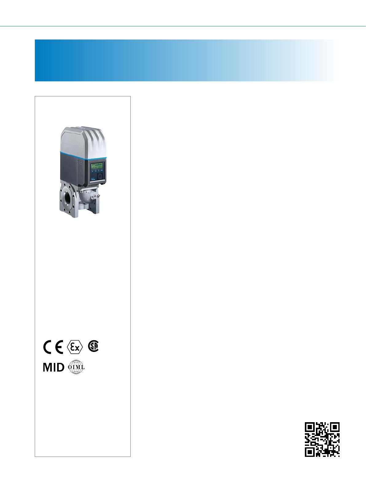
The cutting-edge technology for the
ultimate in measurement accuracy:
The FLOWSIC500 ultrasonic compact
gas meter from SICK ensures highly ac-
curate metering in natural gas distribu-
tion. In absence of mechanical moving
parts, the FLOWSIC500 is a rugged,
reliable, and low-maintenance device
– allowing for a signicant reduction in
operating costs. It is overload-proof, ac-
curate and is monitored by an intelligent
diagnostics system.
The modern interfaces and the option
of wireless communication make it easy
to integrate into remote data manage-
ment systems. Continuous monitoring
provides a transparent picture of the
current device status as well as changes
in the gas quality. When used in transfer
stations and measuring stations, the
FLOWSIC500 provides the security of
a continuous and blockage-free gas
supply.
At a glance
Rugged and time-proven technology:
ultrasound technology
Diagnostics and continuous opera-
tional checks
Measuring capability up to 30% H2 in
the natural gas
Gas Quality Indicator for quantifying
the H2 content
Integrated volume conversion and
load recording
No straight inlet/outlet piping
required
Large measuring span, no moving
parts
Extended interfaces and protocols
Remote communication (DATCOM)
Your benets
Ability to digitize the gas network
Unique remote gas network monitor-
ing based on i-diagnostics™
Ultimate measurement certainty and
safety of continuous gas supply
Simple installation, compatible with
conventional technologies
(turbine and rotary meters)
All-in-one solution: gas ow meter +
volume correction + data registration
+ data communication (DATCOM)
Autarkic operation or failsafe network
operation with battery backup
Reduced maintenance eort thanks
to remote maintenance
Simplied recalibration through
straightforward “cartridge exchange”
CUSTODY TRANSFER MEASUREMENT
IN NATURAL GAS DISTRIBUTION
More information
Fields of application . . . . . . . . . . . . . 13
Detailed technical data. . . . . . . . . . . 13
Measuring ranges, legal for trade . . 15
Ordering information. . . . . . . . . . . . . 15
Dimensional drawing . . . . . . . . . . . . 16
Application areas . . . . . . . . . . . . . . . 19
CUS
®
- www.sick.com/FLOWSIC500
For more information, simply visit the above link to obtain direct access to technical data,
CAD design models, operating instructions, software, application examples, and much more.
flowsIC500 HIGH-PERFORMANCE FLOW MEASUREMENT
Gas flow meters | sICK8026204/2022-09
Subject to change without notice
13
Fields of application
Natural gas distribution
Metering stations in industrial and commercial applications
Building and area metering for municipal and regional gas
suppliers
Critical applications where a continuous gas supply must
be ensured, e.g., in hospitals
Natural gas measurement; complies with all applicable
directives and guidelines
Detailed technical data
The exact device specications and performance data of the product may deviate from the information provided here, and depend on the appli-
cation in which the product is being used and the relevant customer specications. Please contact your local SICK representative for information
about the performance of the FLOWSIC500 for your application.
System
Measured values Volume a.c., volume ow a.c., gas velocity
In addition, for integrated volume correction: volume s.c., volume ow s.c.
Measurement principle Ultrasonic transit time dierence measurement
Measuring medium Natural gas (dry, odorized), natural gas containing up to 30% hydrogen
Measuring ranges
Volume ow, a. c., DN 50
Volume ow, a. c., DN 80
Volume ow, a. c., DN 100
Volume ow, a. c., DN 150
1.0 ... 160 m³/h
2.5 ... 400 m³/h
4.0 ... 650 m³/h
4.0 ... 1,000 m³/h
Repeatability ≤ 0.1%
Accuracy
Qmin up to 0.1 Qmax
0.1 Qmax up to Qmax
Qmin up to 0.1 Qmax
0.1 Qmax up to Qmax
Accuracy class 1; typical error limits
≤ ± 1%
≤ ± 0.5%
Accuracy class 1; maximum allowed error limits
≤ ± 2%
≤ ± 1%
After high pressure ow calibration: ± 0.2% at test pressure, otherwise ± 0.5%
Diagnostic functions Permanent monitoring of measured values, Gas Quality Indicator
Gas temperature 25 °C ... +60 °C
–40 °C ... +70 °C (optional)
Operating pressure PN16 (EN 1092-1): 0 bar(g) ... 16 bar(g)
Class 150 (ASME B16.5): 0 bar(g) ... 20 bar(g)
Ambient temperature 25 °C ... +60 °C
–40 °C ... +70 °C (optional)
Storage temperature –40 °C ... +80 °C
Conformities MID: 2014/32 / EU
OIML R 137-1&2:2012
EN 12405: 2010 (for integrated volume correction)
PTB-A-50.7 (load prole memory)
Ex approvals
IECEx
ATEX
NEC/CEC (US/CA)
Ex ia [ia] IIC T4 Gb, Ex op is IIC T4 Gb
II 2G Ex ia [ia] IIC T4 Gb, II 2G Ex op is IIC T4 Gb
I.S. for Class I Division 1 Groups C and D T4; Ex/AEx ia IIB T4 Ga
Class I, Division 2, Groups A, B, C, and/or D, T4
Enclosure rating IP66
HIGH-PERFORMANCE FLOW MEASUREMENT flowsIC500
Gas flow meters | sICK 8026204/2022-09
Subject to change without notice
14
Digital outputs Congurations:
malfunction, electrically isolated LF pulse + (fmax = 100 Hz)
malfunction, electrically isolated HF pulse + (fmax = 2 kHz)
Encoder + LF pulse, electrically isolated (fmax = 100 Hz)
Encoder + HF pulse, electrically isolated (fmax = 2 kHz)
2x LF pulse, electrically isolated (fmax = 2 kHz / 100 Hz)
LF pulse + RS485 (externally powered)
HF pulse + RS485 (externally powered)
RTU RS485 (externally powered)
RS485 protocol Modbus RTU, Modbus Enron, ISO-17089.1 (DSfG)
Optical interface According to EN 62056-21, Section 4.3
Dimensions (W x H x D) See dimensional drawings
Material in contact with media Aluminum AC-42100-S-T6
Mounting Horizontal or vertical mounting with 0 D straight inlet/outlet piping
Electrical connection
Voltage Intrinsically safe supply: 4.5 ... 16 V DC
Includes 3-month backup battery
Options Autarkic meter conguration (5-year battery life)
Volume correction
Accuracy
Conversion factor C
Accuracy class 0.5
Maximum permitted error limits of
≤ ± 0.5% (at reference conditions)
Correction method PTZ or TZ
Compressibility SGERG88
AGA 8 Gross method 1
AGA 8 Gross method 2
AGA 8 DC92
AGA NX-19
AGA NX-19 mod.
GERG91
Fixed value
Data archives Measurement period archive (5867 entries)
Daily archive (600 entries)
Monthly archive (25 entries)
Log books Event log book (1,000 entries)
Parameter log book (250 entries)
Metrology log book (100 entries)
Gas parameters log book (150 entries)
Pressure sensor
Measuring ranges
Absolute pressure
Gauge pressure
0.8 ... 5.2 bar(a) / 2.0 ... 10 bar(a) / 4.0 ... 20 bar(a) / 0.8… 20 bar(a)
0 ... 4 bar(g) / 0 ... 10 bar(g) / 0 ... 20 bar(g)
Temperature sensor
Measuring ranges
Temperature 25 ... +60 °C
–40 ... +70 °C
Sensor type Platinum resistance sensor, Pt1000 in stainless steel protective pipe
Ambient temperature –40 ... +85 °C
flowsIC500 HIGH-PERFORMANCE FLOW MEASUREMENT
Gas flow meters | sICK8026204/2022-09
Subject to change without notice
15
Custody transfer measuring ranges
Nominal size Meter size Measuring range [m³/h] Measuring span
Min. Max.
DN 50 (2") G 40 1.3 65 1 : 50
G 65 2.0 100 1 : 50
G 100 3.2 160 1 : 50
G 100 1.6 160 1 : 100
G 100 1.0 160 1 : 160
DN 80 (3") G 100 3.2 160 1 : 50
G 160 5.0 250 1 : 50
G 160 2.5 250 1 : 100
G 250 8.0 400 1 : 50
G 250 4.0 400 1 : 100
G 250 2.5 400 1 : 160
DN 100 (4") G 160 5.0 250 1 : 50
G 250 8.0 400 1 : 50
G 250 4.0 400 1 : 100
G 400 13 650 1 : 50
G 400 6.5 650 1 : 100
G 400 4.0 650 1 : 160
DN 150 (6") G 250 8.0 400 1 : 50
G 250 4.0 400 1 : 100
G 400 13 650 1 : 50
G 400 6.5 650 1 : 100
G 400 4.0 650 1 : 160
G 650 20 1,000 1 : 50
G 650 10 1,000 1 : 100
G 650 6.2 1,000 1 : 160
G 650 5.0 1,000 1 : 200
G 650 4.0 1,000 1 : 250
Ordering information
Our regional sales organization would be happy to advise you on what device conguration is best for you.
HIGH-PERFORMANCE FLOW MEASUREMENT flowsIC500
Gas flow meters | sICK 8026204/2022-09
Subject to change without notice
16
Dimensional drawing (Dimensions in mm)
FLOWSIC500, nominal size DN 50
AB
E
D
C
Nominal size Weight Dimensions
A B C D E
DN 50
10.6 153 78
150
71 272
11.4 171
All dimensions in mm. All weights in kg.
FLOWSIC500, nominal size DN 80
AB
E
D
C
Nominal size Weight Dimensions
A B C D E
DN 80 18.3 194 121 171 94 417
20.5 241
All dimensions in mm. All weights in kg.
flowsIC500 HIGH-PERFORMANCE FLOW MEASUREMENT
Gas flow meters | sICK8026204/2022-09
Subject to change without notice
17
FLOWSIC500, nominal size DN 100
AB C
DE
Nominal size Weight Dimensions
A B C D E
DN 100
27, 2 231 159 241 108 476
29,4 300
All dimensions in mm. All weights in kg.
HIGH-PERFORMANCE FLOW MEASUREMENT flowsIC500
Gas flow meters | sICK 8026204/2022-09
Subject to change without notice
18
FLOWSIC500, nominal size DN 150
AB C
DE
Nominal size Weight Dimensions
A B C D E
DN 150 35.0 232 158 450 143 476
All dimensions in mm. All weights in kg.
Pressure sensor
80
4420
Ø 25
M8
Temperature sensor
60
44
Ø 25
M8
120
Ø 5,7
flowsIC500 HIGH-PERFORMANCE FLOW MEASUREMENT
Gas flow meters | sICK8026204/2022-09
Subject to change without notice
19
Application areas
Pressure loss
FLOWSIC500 causes a typical pressure loss of:
10 100 1000 Flow (m³/
h)
Δ
p
natural gas
[mBar]
10
1
0,1
DN50
DN80
DN100
DN150
Nominal size
Reference density natural gas: ρ = 0.83 kg/m³
Reference density for natural gas: ρ = 0.83 kg/m3
DN 50
DN 80
DN 100
DN 150
Nominal size
ΔpNatural gas [mbar]
Flow (m3/h)
HIGH-PERFORMANCE FLOW MEASUREMENT flowsIC500
Speed of sound
The speed of sound in the measured gas must be within the range of 300 m/s to 600 m/s.
Gas flow meters | sICK 8026204/2022-09
Subject to change without notice
20
Methane concentration (CH4) in natural gas
For very high methane concentrations, the FLOWSIC500 requires a minimum operating pressure for meter sizes of DN 80 to
DN 150. Methane has a damping eect on the signal transmission.
Meter size DN 50
Meter size DN 80 / DN 100 / DN 150
0.2
0.4
0.6
0.8
1
1.2
1.4
-40 -30 -20 010204050
1.8
0
1.6
2
30 60
70
-10
v
max
in ft/s
Nominal pipe size in ″
1-path sos = 340 m/s
1.01325 bar(a)
1-path sos = 340 m/s
Gas temperature [°C]
Pressure [bar(a)]
Methane concentration 0% ... 100% Reference pressure at 0 m above sea level
1.01325 bar(a)
0.2
0.4
0.6
0.8
1
1.2
1.4
-40 -30 -20 -10 0102
060
1.8
0
1.6
30 40
Gastemperatur [°C]
100 % 98 % 93 % / 95 %
1.01325 bar(a)
1.01325 bar(a)
Pressure [bar(a)]
Gas temperature [°C]
100%
99%
98%
96% / 97%
93% / 95%
flowsIC500 HIGH-PERFORMANCE FLOW MEASUREMENT
  • Page 1 1
  • Page 2 2
  • Page 3 3
  • Page 4 4
  • Page 5 5
  • Page 6 6
  • Page 7 7
  • Page 8 8
  • Page 9 9
  • Page 10 10
  • Page 11 11
  • Page 12 12
  • Page 13 13
  • Page 14 14
  • Page 15 15
  • Page 16 16
  • Page 17 17
  • Page 18 18
  • Page 19 19
  • Page 20 20
  • Page 21 21
  • Page 22 22
  • Page 23 23
  • Page 24 24

SICK FLOWSIC500 Product information

Category
Measuring, testing & control
Type
Product information

SICK FLOWSIC500: Experience a new era of gas flow measurement with unparalleled accuracy, reliability, and connectivity. Embrace the digital transformation of your gas network with this innovative ultrasonic gas flow meter. Unleash the power of remote control, fleet monitoring, and real-time gas quality insights to optimize your operations like never before.

Ask a question and I''ll find the answer in the document

Finding information in a document is now easier with AI