Page is loading ...

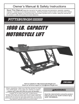
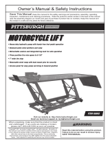
MODEL H8011
ATV LIFT
1500 LB. CAPACITY
INSTRUCTION SHEET
COPYRIGHT © AUGUST, 2006 BY GRIZZLY INDUSTRIAL, INC.
WARNING: NO PORTION OF THIS MANUAL MAY BE REPRODUCED IN ANY SHAPE
OR FORM WITHOUT THE WRITTEN APPROVAL OF GRIZZLY INDUSTRIAL, INC.
#TS8377 PRINTED IN CHINA

-2-
H8011 ATV Lift - 1500 lb. Capacity
Safety Instructions for the ATV Lift
Like all machines there is danger associ-
ated with this machine. Accidents are fre
-
quently caused by lack of familiarity or fail
-
ure to pay attention. Use this machine with
respect and caution to lessen the possibil
-
ity of operator injury. If normal safety pre
-
cautions are overlooked or ignored, serious
personal injury may occur.
No list of safety guidelines can be com-
plete. Every shop environment is different.
Always consider safety first, as it applies
to your individual working conditions. Use
this and other machinery with caution and
respect. Failure to do so could result in
serious personal injury, damage to equip-
ment, or poor work results.
1. READ THROUGH THIS ENTIRE
INSTRUCTION SHEET BEFORE USING
THE LIFT.
Failure to understand and follow
all operational and safety instructions may
result in death or serious injury.
2. TRAINED PERSONNEL ONLY.
This lift and
its load represent serious crushing hazards
and should be handled with respect and c
au-
tion to lessen the possibility of injury
. Keep
all untrained persons and visitors away from
the lift at all times. Do not allow anyone to
sit or stand on the platform at any time
. Stay
clear of the lift
when raising or lowering.
3. LIFT STABILITY. Failure to maintain lift
and load stability causes load to become
unstable and may result in serious injury
from loss of control. Use this lift on a stable
and dry surface that is capable of sustaining
the load. Get help with loading and unload-
ing to maintain control of the load and do so
only when the lift platform is fully lowered to
the ground.
4. OPERATION SAFETY. Center the load on
the platform and secure it with approp
riate
strapping. Raise and lower the lift slowly and
in a controlled fashion. Do not add any addi
-
tional weight to the lift platform after it has
been raised. ALWAYS engage the
locking
plate with the safety latches when the lift is
in a raised position.
5. PERSONAL SAFETY APPAREL. To assist
in maintaining stable footing while loading or
unloading the lift, wear non-skid footwear.
Secure long hair, loose clothing and other
personal items that may be caught in moving
parts.
6. LIFT DESIGN LIMITS. Exceeding the design
limits of this lift will cause the lift to fail and
may cause death or serious personal injury.
Do not exceed the rated load capacity of
1500 lbs. for this lift. Refer to the weight
specifications of the vehicle you intend to
load. Do not make any modifications to any
part of this lift. Do not use this lift for any
purpose other than lifting ATV vehicles. DO
NOT use this lift for motorcyles.
7. MOVING THE LIFT. The lift must be ful
ly
lowered to the ground before moving it to
avoid tipping hazards.
Remove the leading
plate and the hydraulic pump before moving
the lift to avoid damaging these items.
Get
help in moving the main lift to avoid per
-
sonal inju
ry.
8. MAINTENANCE/SERVICE. Keep the lift
platform free from fluids and debris that may
cause the load to slip. Problems concerned
with any moving parts or accessories MUST
be investigated and corrected. If at any time
you are experiencing difficulties performing
the intended operation, stop using the lift!
Contact our Technical Support Department
at (570) 546-9663.

-3-
H8011 ATV Lift - 1500 lb. Capacity
Introduction
The Model H8011 ATV Lift features a low-profile,
heavy-duty design that is easy to use, and will lift
your ATV to an optimal working height. The dual
function hydraulic pumping system can be oper
-
ated manually or with an air compressor, and will
reliably lift vehicles up to 1500 lbs.
Inventory (Figure 1)
A. Main Lift Assembly ..................................... 1
B. Air/Manual Hydraulic Pump ........................ 1
C. Leading Plate ............................................. 1
Specifications
Capacity .................................................1500 lbs.
Length..........................................................78
3
/4"
Width ...........................................................47
1
/4"
Maximum Lift Height ..................................
32
9
/32"
Minimum Lift Height .....................................
7
5
/32"
Air Inlet Fitting ........................................
1
/4" NPT
Air Pressure Required ..................... 100-125 PSI
Assembly Instructions
1. Place the hydraulic pump by the side of the
lift (see Figure 1
).
2. Attach the hydraulic hose connector at the
end of the main lift assembly hose to the cou
-
pling on the hydraulic pump (see Figure 2
).
3. Connect the air valve to an air source that is
rated between 100 and 125 PSI
.
4. Position the leading plate studs into the two
corresponding holes at the rear of the plat
-
form.
Before First Use
To ensure proper operation before using the lift
with a load, the air pump must be lubricated, the
hydraulic fluid level checked, air bled from the
hydraulic system, and the lift tested.
To lubricate the
air pump:
1. Pour
1
/3 oz. of good quality air tool lubricant
into the
1
/4" NPT air inlet fitting while squeez-
ing the lever of the air valve (see Figure 2
).
2. To ensure an even distribution of the lubri-
cant:
a. Connect the air inlet fitting to an air
source rated between 100 and 125 PSI.
b. While pressing down on the release foot
pedal (see Figure 2
), squeeze the lever
on the air valve for three seconds.
Figure 1. Model H8011 inventory.
A
B
C
Figure 2. Air and hydraulic pump connections.
Hydraulic Hose Connector
Air Pump
Release Foot
Pedal
Lift Foot Pedal
Air Valve

-4-
H8011 ATV Lift - 1500 lb. Capacity
Operation Instructions
To raise the lift with a load:
1. Open the vent valve.
2. Position the lift on a flat, stable surface that is
capable of sustaining the load.
3. Use the two adjusting handles (see Figure 4)
to level the lift.
4. Push—DO NOT drive—the vehicle up the
leading plate and onto the platform.
5. Center and secure the load to the platform
with appropriate strapping.
Adjusting Handles
Figure 4. Location of adjusting handles.
To check the hydraulic fluid level:
1. To ensure that all of the hydraulic fluid from
the ram is returned to the hydraulic pump
reservoir, the lift must be fully lowered to the
ground.
2. Remove the vent valve (see Figure 3).
3. Using a standard hydraulic oil, make sure the
fluid level is
1
/2" from the top.
4. Replace the vent valve and tighten
1
/2 turn
past hand tightened.
Note: When using the lift, rotate the top knob of
the vent valve counterclockwise until it stops.
This will allow the hydraulic pump reservoir
to breath during lift use. Close the vent valve
when not in use.
To bleed the air from the hydraulic system:
1. Open the vent valve.
2. The lift must be fully lowered to force the fluid
from the ram back into the hydraulic pump
reservoir.
3. Fully depress the smaller release foot pedal
and pump the larger lift pedal 20 times.
4. To allow the air to separate from the fluid
and escape through the vent valve, leave
the hydraulic pump inactive for at least one
hour.
Vent Valve
Figure 3. Location of vent valve on hydraulic
pump.
To test the hydraulic system:
1. Follow the procedures in the Operation
Instructions section to raise and lower the
lift WITHOUT a load.
2. Make sure that the lift moves evenly and that
it remains at the working height after pump
-
ing is stopped. Strange operation or noises
MUST be investigated and corrected before
operating the lift further. For repairs or parts
replacement, contact our Tech Support at
(570) 546-9663.

-5-
H8011 ATV Lift - 1500 lb. Capacity
NOTICE
Remove the leading plate before raising
the lift. The leading plate is not designed to
be raised with the lift or act as a platform
for the load. Failure to heed this warning
may result in property damage.
6. Move the safety lever to the right as shown
in Figure 5. This will lower the locking plate,
engaging the safety latches as the lift is
raised.
7. Connect the air valve to an air source rated
between 100 and 125 PSI.
— If an air source is not available, use the
larger lift foot pedal on the hydraulic
pump to lift the load.
8. Squeeze the lever on the air valve to raise
the load to slightly above the desired working
height.
9. Slowly lower the lift until the locking plate is
fully engaged with the next lower safety latch
to ensure that the lift will not unexpectedly
drop.
Figure 5. Safety lever to the right.
5. Remove the leading plate BEFORE raising
the lift.
To lower the lift and load:
1. Open the vent valve.
2. Remove all tools and other obstructions from
under and near the lift, and make sure that all
persons are clear of the lift.
3. Raise the lift slightly to disengage the locking
plate from the safety latches.
Figure 6. Safety lever to the left.
3. Move the safety lever to the left and down
into the slot as shown in Figure 6, which
will keep the locking plate from engaging the
safety latches
.
4. In a controlled fashion, press down on the
smaller release foot pedal to lower the lift.
Move the safety lever to the right before rais-
ing the lift. This will ensure that the locking
plate is lowered and engaged with the safety
latches to prevent accidental lowering of the
lift. Failure to carefully follow this procedure
may result in death or serious injury.
Only load and unload the lift when it is fully
lowered to the ground to ensure the load
does not tip or fall from the lift. Failure to do
so may result in serious injury and property
damage.
NOTICE
Never store the lift in any position other
than fully lowered. Otherwise, the ram will
rust and become pitted overtime, leading
to seal failures.

-6-
H8011 ATV Lift - 1500 lb. Capacity
Maintenance
Regular periodic maintenance on your Model
H8011 ATV Lift will ensure its optimum perfor
-
mance. Make a habit of inspecting your lift each
time you use it.
Maintenance Procedures
• Clean all painted surfaces after each use. Do
not allow surfaces to become slippery.
• Every 6–12 months, inspect the ram (refer to
Part 28, H8011 Parts Breakdown on
Page
6) and remove any signs of corrosion. Wipe
a thin coat of a good quality hydraulic oil to
protect the chrome surfaces of the ram.
If you need help with your new ATV lift, call our
Tech Support at: (570)546-9663.
• If the lift feels spongy while raising or the ram
will not lift the load, bleed the air from the
hydraulic pump as detailed in Before First
Use on Page 3.
• Use a light machine oil to lubricate all pivot
points of the lifting arms (refer to Parts 5 &
27, H8011 Parts Breakdown on
Page 6)
every 6–12 months, depending on frequency
of use.
• The hydraulic pump and ram are sealed and
pre-adjusted at the factory, and require no
internal maintenance.

-7-
H8011 ATV Lift - 1500 lb. Capacity
H8011 Parts Breakdown

-8-
H8011 ATV Lift - 1500 lb. Capacity
REF PART # DESCRIPTION REF PART # DESCRIPTION
1 PH8011001 PLATFORM 27 PH8011027 INSIDE LIFTING ARM
2 PH8011002 SLIDING PLATE 28 PH8011028 RAM
3 PH8011003 LEADING PLATE 29 PH8011029 HYDRAULIC HOSE
4 PH8011004 STEEL WHEEL 30 PH8011030 HYDRAULIC HOSE COUPLER
5 PH8011005 OUTSIDE LIFTING ARM 31 PH8011031 HYDRAULIC PUMP
6 PH8011006 BASE 31-1 PH8011031-1 VENT VALVE
7 PB74M HEX BOLT M10-1.5 X 20 32 PH8011032 LIFT FOOT PEDAL
8 PW04M FLAT WASHER 10MM 33 PH8011033 RUBBER PAD
9 PH8011009 LOCKING PLATE 34 PH8011034 RELEASE FOOT PEDAL
10 PN03M HEX NUT M8-1.25 35 PLN03M LOCK NUT M6-1
11 PLW04M LOCK WASHER 8MM 36 PSB07M CAP SCREW M6-1 X 30
12 PW01M FLAT WASHER 8MM 37 PB87M HEX BOLT M8-1.25 X 15
13 PH8011013 DRILLED HEX BOLT M8-1.25 X 30 38 PH8011038 AIR HOSE
14 PH8011014 SAFETY LATCH 39 PH8011039 AIR VALVE
15 PN02M HEX NUT M10-1.5 40 PH8011040 QUICK COUPLER MALE 1/4 NPT
16 PH8011016 HOLLOW SCREW M10-1.5 X 30 41 PH8011041 SAFETY LEVER
17 PH8011017 LOCKING PLATE BASE 42 PN09M HEX NUT M12-1.75
18 PH8011018 SAFETY WIRE 43 PH8011013 DRILLED HEX BOLT M8-1.25 X 30
19 PH8011019 CAP SCREW M16-2 X 140 44 PLN05M LOCK NUT M10-1.5
20 PW08M FLAT WASHER 16MM 45 PLW06M LOCK WASHER 10MM
21 PLN07M LOCK NUT M16-2 46 PH8011046 AIR PUMP
22 PB133M HEX BOLT M16-2 X 90 47 PH8011047 CRUSHING HAZARD LABEL
23 PLW10M LOCK WASHER 16MM 48 PH8011048 PINCH HAZARD LABEL
24 PN13M HEX NUT M16-2 49 PH8011049 FALLING HAZARD LABEL
25 PH8011025 ADJUSTING HANDLE 50 PH8011050 BREAKING HAZARD LABEL
26 PH8011026 ROTATABLE FOOT 51 PH8011051 MACHINE ID LABEL
H8011 Parts List
/