Page is loading ...

Instruction Manual
Please read this instruction manual carefully before use.
IMPORTANT
PLEASE READ THESE INSTRUCTIONS CAREFULLY. NOTE THE SAFETY INSTRUCTIONS AND
WARNINGS. USE THE PRODUCT CORRECTLY AND WITH CARE FOR THE PURPOSE FOR WHICH IT IS
INTENDED. FAILURE TO DO SO MAY CAUSE DAMAGE TO PROPERTY AND/OR PERSONAL INJURY.
PLEASE KEEP THIS INSTRUCTION MANUAL SAFE FOR FUTURE USE.

1. SAFETY INSTRUCTIONS AND WARNINGS
1.1 Use a qualified person to maintain the lift in good condition. Keep it clean for best and safest
performance.
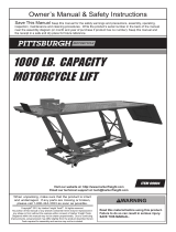
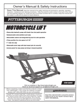
1.2 The maximum load is 1500lbs. DO NOT exceed this rated capacity.
1.3 Use this lift for lifting purpose only. DO NOT use it for any other purpose it is not designed to perform.
1.4 Keep children and unauthorized persons away from the work area.
1.5 Remove ill fitting clothing. Remove ties, watches, rings and other loose jewelry, and contain long hair.
1.6 Wear ANSI approved safety goggles when operating the lift.
1.7 Keep proper balance and footing, do not overreach and wear nonskid footwear.
1.8 Only use this lift on a surface that is stable, level, dry and not slippery, and capable of sustaining the load.
Keep the surface clean, tidy and free from unrelated materials and ensure that there is adequate
lighting.
1.9 Before lifting load, stabilize the lift by turning the adjusting screws down. The lift must only be used in a
static position for lifting and lowering loads. Ensure that the load remains stable at all times.
1.10 Ensure the load is adequately secured to the lift with appropriate straps.
1.11 When the load has been raised to the working height, make sure the safety handle (35) is on your right
side and the locking plate is locked in corresponding position to prevent accidental lowering.
1.12 Before lowering lift ensure that there are no obstructions underneath and that all persons are standing
clear.
1.13 Always keep your hands and feet away from moving parts.
1.14 DO NOT use the lift if damaged, any suspect parts are noted or it has been subjected to a shock load.
1.15 DO NOT operate the lift when you are tired or under the influence of alcohol, drugs or any intoxicating
medication.
1.16 DO NOT allow untrained persons to operate the lift.
1.17 DO NOT make any modifications to the lift.
1.18 DO NOT expose the lift to rain or snow.
1.19 If the lift needs repairing and/or there is any part which needs to be replaced, have it repaired by
authorized technicians and only use the replacement parts supplied by the manufacturer.
1.20 WARNING: the warnings, cautions and instructions discussed in this instruction manual cannot cover all
possible conditions and situations that may occur. It must be understood by the operator that common
sense and caution are factors which cannot be built into this product, but must be supplied by the
operator.
2. SPECIFICATIONS
Capacity …………………1500Lb (680Kg)
Width …………1190mm (46-3/4”)
Length …………2000mm (78-3/4”)
Minimum Height…………185mm (7-1/4”)
Maximum Height…………800mm (31-1/2”)
Air Pressure ………… 0.75-0.85Mpa
Air Inlet Fitting…………1/4inch NPT

3. ASSEMBLY
Unpack the lift and check contents with list below. Should there be any damaged or missing parts, contact your
supplier immediately
Content
·Main Lift Assembly ·Air/Manual Hydraulic Pump Assembly ·Leading plate
3.1 Put the air hydraulic pump by the side of the lift station. Connect the oil hose coupler (28) to the hole in the
air hydraulic pump.
3.2 Attach the leading plate (03) to end of platform (01).
4. BEFORE FIRST USE
4.1 Before first use of this product, pour a teaspoon of good quality, air tool lubricant into the air supply inlet of
the lift control valve, connect to air supply and operate for 3 seconds to evenly distribute lubricant.
4.2 Leave the pump for one hour to allow the oil to settle before purging the system.
NOTE: Failure to allow sufficient time for the oil to settle could result in air remaining in the oil. In this event,
the pump will not purge completely first time and a second purge will be required.
4.3 Purge away air from the hydraulic system:
Manual operating system: purge the hydraulic circuit to eliminate any air in the system by fully pressing
the release foot pedal and pumping the lift foot pedal 15 to 20 times.
Air operating system: connect the quick coupler-male into the air supply hose quick coupler-female and
fully press the release foot pedal, then turn on the air valve a’ssy letting the pump
work for 30 seconds to eliminate any air in the hydraulic system.
4.4 Test the lift, unloaded: move the safety handle (35) to your right side, raise the lift to full height, then move
the safety handle to your left side in the dent and lower the lift. Depress release foot pedal slowly to
control the rate of descent.
5. OPERATING INSTRUCTIONS
WARNING! Ensure that you read, understand and apply the safety instructions and warnings before
use.
WARNING! Do not attempt to overload the lift.
5.1 Position the lift in a suitable area, turning the adjusting screw (29) down to make sure the lift is stable and
level on the surface, checking that the surface on which the lift will stand is solid and flat (preferably
concrete).
5.2 Wheel the ATV or motorcycle up the leading plate and onto the platform.
WARNING! The motorcycle must be fully supported by the lift platform (01) before lifting. DO NOT put
the rear wheel of the motorcycle on the leading plate (03) and DO NOT use the leading
plate (03) to support the weight of the motorcycle when lifting.
WARNING! The leading plate (03) is only used to help you to wheel the motorcycle onto the platform
when the lift is at its lowest position.
5.3 Strap the ATV or motorcycle securely to the platform.
NOTE: Before raising the lift, move the safety handle (35) to your right side.
5.4 Connect the quick coupler-male into the air supply hose quick coupler-female, then turn on the air valve
assy to raise the lift. When air source is not available, pump the lift foot pedal to raise the lift.
5.5 When the platform has been raised to the working height, turn off the air valve or stop pumping.
NOTE: At this moment, make sure the safety handle (35) is on your right side and the locking plate (06)

is locked in corresponding pair of safety latch to prevent accidental lowering.
5.6 When work is done, remove all tools from under the lift before lowering. Raise the lift by pumping the lift
foot pedal several times or by air to let the locking plate (06) free from its locking position, then move the
safety handle (35) to your left side and fix it in the dent, SLOWLY press the release foot pedal to GENTLY
lower the lift.
NOTE: Lower the ATV or motorcycles slowly, in a controlled fashion. Never allow the ATV or motorcycle to
drop quickly.
5.7 When the lift is fully lowered, untie the ATV or motorcycle, open the vise jaws and remove the ATV or
motorcycle from the lift.
6. MAINTENANCE
6.1 When not in use, the lift must be stored in the lowest position in a dry location to minimize ram and piston
corrosion.
6.2 Keep the lift clean and wipe off any oil or grease. Lubricate all moving parts.
6.3 Periodically check the ram and piston for signs of corrosion. Clean exposed areas with a clean oiled cloth.
6.4 Before each use check all parts. If any part of the lift is damaged or suspect, remove the lift from service
and take necessary action to repair.
6.5 Purge the hydraulic system to eliminate any air in the system if lift efficiency drops as described in section
4.3.
6.6 Check the hydraulic oil level. If it is not adequate, remove the rubber plug on the pump and add hydraulic
oil as necessary. DO NOT use brake fluid or any other improper fluid. Only a good quality hydraulic jack
oil can be used.
PARTS LIST
No.
Desc.
Q'ty
No.
Desc.
No.
No.
Desc.
Q'ty
01
Platform
1
17
Screw
2
33
Bolt
1
02
Sliding Plate
1
18
Safety Wire
1
34
Nut
1
03
Leading Plate
1
19
Nut
2
35
Handle
1
04
Outside Lifting Arm
1
20
Washer
8
36
Handle Ball
1
05
Inside Lifting Arm
1
21
Screw
2
37
Nut
6
06
Locking Plate Assy
1
22
Bolt
2
38
Bolt
12
07
Base Assy
1
23
Lock Washer
6
39
Stop Plate
1
08
Washer
22
24
Bolt
4
40
Pipe Plug
4
09
R-Pin
2
25
Ram Assy
1
41
Rubber Pad 1
2
10
Steel Wheel
4
26
Oil Hose Assy
1
42
Stationary Vise Assy
1
11
Bolt
8
27
Dust Cover
1
43
Rubber Pad 2
2
12
Lock Washer
8
28
Oil Hose Coupler
1
44
Bolt
24
13
Nut
2
29
Adjusting Screw
2
45
Movable Vise Assy
1
14
Washer
4
30
Rotatable Foot
2
46
Bolt
4
15
Bolt
1
31
Nut
1
47
Adjustable Shelf
1
16
Nut
16
32
Connection Plate
1

EXPLODED DRAWING
/