15
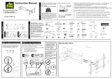
Full Motion Mount for TVs 47" - 70"DX-HTVMM1703-C
One-year limited warranty - Dynex
Definitions:
The Distributor* of Dynex branded products warrants to you, the original purchaser of this new Dynex-branded product (“Product”), that the Product shall be free of defects in the
original manufacturer of the material or workmanship for a period of one (1) year from the date of your purchase of the Product (“Warranty Period”).
For this warranty to apply, your Product must be purchased in the United States or Canada from a Best Buy branded retail store or online at www.bestbuy.com, or www.bestbuy.ca
which are packaged with this warranty statement.
How long does the coverage last?
The Warranty Period lasts for 1 year (365 days) from the date you purchased the Product. Your purchase date is printed on the receipt you received with the Product.
What does this warranty cover?
During the Warranty Period, if the original manufacture of the material or workmanship of the Product is determined to be defective by an authorized Dynex repair center or store
personnel, Dynex will (at its sole option): (1) repair the Product with new or rebuilt parts; or (2) replace the Product at no charge with new or rebuilt comparable products or parts.
Products and parts replaced under this warranty become the property of Dynex and are not returned to you. If service of Products or parts are required after the Warranty Period
expires, you must pay all labor and parts charges. This warranty lasts as long as you own your Dynex Product during the Warranty Period. Warranty coverage terminates if you sell or
otherwise transfer the Product.
How to obtain warranty service?
If you purchased the Product at a Best Buy retail store location, please take your original receipt and the Product to any Best Buy store. Make sure that you place the Product in its
original packaging or packaging that provides the same amount of protection as the original packaging. If you purchased the Product from a Best Buy online web site
(www.bestbuy.com or www.bestbuy.ca), mail your original receipt and the Product to the address listed on the web site. Make sure that you put the Product in its original
packaging or packaging that provides the same amount of protection as the original packaging.
To obtain warranty service, in the United States call 1-888-BESTBUY or in Canada call 1-866-BESTBUY. Call agents may diagnose and correct the issue over the phone.
Where is the warranty valid?
This warranty is valid only in the United States and Canada at Best Buy branded retail stores or websites to the original purchaser of the product in the county where the original
purchase was made.
What does the warranty not cover?
This warranty does not cover:
• Customer instruction/education
• Installation
•Set up adjustments
• Cosmetic damage
• Damage due to acts of God, such as power surges
•Accident(s)
•Misuse
•Abuse
• Negligence
• Commercial purposes/use, including but not limited to use in a place of business or in communal areas of a multiple dwelling condominium or apartment complex, or
otherwise used in a place of other than a private home.
• Modification of any part of the Product, including the antenna
• Display panel damaged by static (non-moving) images applied for lengthy periods (burn-in).
• Damage due to incorrect operation or maintenance
• Connection to an incorrect voltage or power supply
• Attempted repair by any person not authorized by Dynex to service the Product
• Products sold “as is” or “with all faults”
• Consumables, including but not limited to batteries (i.e. AA, AAA, C etc.)
• Products where the factory applied serial number has been altered or removed
• Loss or Theft of this product or any part of the product
• Display panels containing up to three (3) pixel failures (dots that are dark or incorrectly illuminated) grouped in an area smaller than one tenth (1/10) of the display size or
up to five (5) pixel failures throughout the display. (Pixel based displays may contain a limited number of pixels that may not function normally.)
• Failures or Damage caused by any contact including but not limited to liquids, gels or pastes.
REPAIR REPLACEMENT AS PROVIDED UNDER THIS WARRANTY IS YOUR EXCLUSIVE REMEDY FOR BREACH OF WARRANTY. DYNEX SHALL NOT BE LIABLE FOR ANY INCIDENTAL OR
CONSEQUENTIAL DAMAGES FOR THE BREACH OF ANY EXPRESS OR IMPLIED WARRANTY ON THIS PRODUCT, INCLUDING, BUT NOT LIMITED TO, LOST DATA, LOSS OF USE OF YOUR
PRODUCT, LOST BUSINESS OR LOST PROFITS. DYNEX PRODUCTS MAKES NO OTHER EXPRESS WARRANTIES WITH RESPECT TO THE PRODUCT, ALL EXPRESS AND IMPLIED WARRANTIES
FOR THE PRODUCT, INCLUDING, BUT NOT LIMITED TO, ANY IMPLIED WARRANTIES OF AND CONDITIONS OF MERCHANTABILITY AND FITNESS FOR A PARTICULAR PURPOSE, ARE LIMITED
IN DURATION TO THE WARRANTY PERIOD SET FORTH ABOVE AND NO WARRANTIES, WHETHER EXPRESS OR IMPLIED, WILL APPLY AFTER THE WARRANTY PERIOD. SOME STATES,
PROVINCES AND JURISDICTIONS DO NOT ALLOW LIMITATIONS ON HOW LONG AN IMPLIED WARRANTY LASTS, SO THE ABOVE LIMITATION MAY NOT APPLY TO YOU. THIS WARRANTY
GIVES YOU SPECIFIC LEGAL RIGHTS, AND YOU MAY ALSO HAVE OTHER RIGHTS, WHICH VARY FROM STATE TO STATE OR PROVINCE TO PROVINCE.
1-800-305-2204
www.dynexproducts.com
DYNEX is a trademark of Best Buy and its affiliated companies
Distributed by Best Buy Purchasing, LLC
7601 Penn Ave South, Richfield, MN 55423 U.S.A.
©2016 Best Buy. All rights reserved
Made in China
DX-HTVMM1703-C_16-0713_MAN_V2_ENG.fm Page 15 Thursday, October 6, 2016 10:47 AM