Page is loading ...

INSTALLATION & OPERATING
INSTRUCTIONS
84 Professional
Gas-Fired
Pool & Spa
Heater
Catalog No. 6000.65G Effective: 09-30-18 Replaces: 05-15-18 P/N 241464 Rev. 8
WARNING: If these instructions are not followed exactly, a fire or explosion may result
causing property damage, personal injury or death.
WHAT TO DO IF YOU SMELL GAS:
• Do not try to light any appliance.
• Do not touch any electrical switch; do not use any phone in your building.
• Immediately call your gas supplier from a neighbor's phone. Follow the gas sup-
plier's instructions.
• If you cannot reach your gas supplier, call the fire department.
Installation and service must be performed by a qualified installer, service agency or
the gas supplier.
This manual should be maintained in legible condition and kept adjacent to the heater or in a safe place for future
reference.
Low NOx Models
259B & 409B
Do not store or use gasoline or other flammable vapors and liquids in the vicinity of
this or any other appliance.

WATER CHEMISTRY
(Corrosive water voids all warranties)
For your health and the protection of your pool equipment, it is essential that your
water be chemically balanced. The following levels must be used as a guide for bal-
anced water.
Recommended Level(s) Fiberglass Pools Fiberglass Spas
Other Pool & Spa
Types
Water Temp. (Deg. F) 68 to 88 89 to 104 68 to 104
pH 7.3 to 7.4 7.3 to 7.4 7.6 to 7.8
Total Alkalinity (PPM) 120 to 150 120 to 150 80 to 120
Calcium Hardness (PPM) 200 to 300 150 to 200 200 to 400
Salt (PPM) 4500 MAXIMUM 4500 MAXIMUM 4500 MAXIMUM
Free Chlorine (PPM)* 2 to 3 2 to 3 2 to 3
Total Dissolved Solids (PPM) 3000 MAXIMUM** 3000 MAXIMUM** 3000 MAXIMUM**
* Free Chlorine MUST NOT EXCEED 5 PPM!
• Occasional chemical shock dosing of the pool or spa water should not damage the
heater providing the water is balanced.
• Automatic chemical dosing devices and salt chlorinators are usually more efficient
in heated water, unless controlled, they can lead to excessive chlorine level which
can damage your heater, and which is not covered under warranty. A check
valve should be installed between the heater outlet and a chlorinator or other chem-
ical dosing device.
• Further advice should be obtained from your pool or spa builder, accredited pool
shop, or chemical supplier for the correct levels for your water.
2
** In salt water chlorinated pools, the total TDS can be as high as 6000 ppm.
Rev. 8 reflects the following changes:
Updated illustration on page 44.
Updated parts list on page 46.

3
CONTENTS
2
Water Chemistry
4 WARNINGS
7 Lighting & Shutdown Instructions
8 Pool & Spa Water Chemistry
8 Automatic Chlorinators & Chemical Feeders
8 Cold Weather Operation
8 Winterizing the Pool & Spa Heater
10 Code Requirements
11 Clearances
11 Outdoor Heater Installation
13 Florida Building Code
14 Indoor Heater Installation
14 Specifications and Dimensions
16 Combustion and Ventilation Air
16 Direct Vent & Ducted Combustion Air
Systems
17 Venting
18 Support of Vent Stack
18 Vent Terminal Location
19 Venting Installation Tips
19 Venting Configurations
19 Natural Draft Vertical Venting (Category I)
Fan-Assisted
20 Horizontal Through-the-Wall Direct Venting
(Category III) Fan-Assisted
21 Direct Vent - Horizontal
22 Direct Vent - Vertical
23 Outdoor Installation
24 Gas Supply Connections
24 Gas Pressure Adjustment Locations
25 Pipe Sizing For Gas Connections
24 Heat Exchanger Pressure Drop Tables
25 Flow Rates
25 Internal Automatic Bypass Valve
25 External Auxiliary Bypass Valve
25 Auxiliary Bypass Valve Adjustment
25 Pressure Relief Valve Installation
26 Electrical Wiring
2
7 Transformer Wiring
28 Optional Left-Hand Wiring
28 Plumbing—Water Connections
29 Loose Plumbing Parts
3
2 Wiring Diagram
33 General Location of Controls
34 Control Adjustments
34 Control Panel Removal
35 Thermostat Operation - Direct Spark Board
37 Status and Diagnostics
38 Remote Control Installation and Operation
38 Remote Operation
38 Activating the Remote
39 Remote Control Wiring
39 2-Wire Remote Control
39 3-Wire Remote Control
40 Time Clock / Fireman’s Switch
40 High Limits
40 Flow Switch
40 Air Pressure & Blocked Vent Switches
40 Adjusting Valve Manifold Pressure
41 Visual Inspection
41 Electrical
41 Orifice Removal
41 Gas and Orifice Selection
41 Igniter Removal
42 Mechanical
43 Control Logic - Flow Chart
44 Illustrated Parts List
45 Part Numbers
47 Important Instructions for the
Commonwealth of Massachusetts
5 PART ONE
OWNER'S OPERATING INSTRUCTIONS
5 SECTION 1
START-UP PROCEDURES
6 SECTION 2
CAUTION
6 SECTION 3
MAINTENANCE & CARE PROCEDURES
10 SECTION 3
INSTALLATION INSTRUCTIONS
10 SECTION 2
GENERAL SPECIFICATIONS
9 SECTION 1
RECEIVING EQUIPMENT
9 PART TWO
INSTALLATION & SERVICE INSTRUCTIONS
3
3 SECTION 4
SERVICING INSTRUCTIONS
42 SECTION 5
TROUBLESHOOTING
44 SECTION 6
REPLACEMENT PARTS

4
DANGER:
I
ndicates the presence of immediate hazards which will cause severe
personal injury, death or substantial property damage if ignored.
WARNING:
Indicates the presence of hazards or unsafe practices which could cause
severe personal injury, death or substantial property damage if ignored.
CAUTION:
Indicates the presence of hazards or unsafe practices which could cause
minor personal injury or product or property damage if ignored.
NOTE:
Indicates special instructions on installation, operation, or maintenance which
are important but not related to personal injury hazards.
WARNINGS—Pay Attention to These Terms
DANGER: Failure to install the draft hood on indoor
installations and properly vent the heater to the
outdoors as outlined in the Venting section of this
manual can result in unsafe operation of the heater.
To avoid the risk of fire, explosion, or asphyxiation
from carbon monoxide, never operate this heater
unless it is properly vented and has an adequate air
supply for proper operation. Be sure to inspect the
vent system for proper installation at initial start-up;
and at least annually thereafter. Refer to the
Maintenance section of this manual for more
information regarding vent system inspections.
DANGER: Make sure the gas on which the heater
will operate is the same type as that specified on the
heater rating plate.
DANGER: When servicing or replacing components
that are in direct contact with the water, be certain
that:
• There is no pressure in the heater. (Pull the release
on the relief valve. Do not depend on the pressure
gauge reading).
• The heater water is not hot.
• The electrical power is off.
WARNING: All venting types must be of the same
material or product throughout the entire exhaust
installation to ensure proper securing and sealing.
WARNING: Altering any Raypak pressure vessel
by installing replacement heat exchangers, tube
bundle headers, or any ASME parts not
manufactured and/or approved by Raypak will
instantly void the ASME and/or CSA ratings of the
vessel and any Raypak warranty on the vessel.
Altering the ASME and/or CSA ratings of the vessel
also violates national, state, and local approval
codes.
WARNING: Both natural gas and propane have an
odorant added to aid in detecting a gas leak. Some
people may not physically be able to smell or
recognize this odorant. If you are unsure or
unfamiliar with the smell of natural gas or propane,
ask your local gas supplier. Other conditions, such
as "odorant fade," which causes the odorant to
diminish in intensity, can also hide, camouflage, or
otherwise make detecting a gas leak by smell more
difficult.
WARNING: Do not install within 3 feet of a heat
pump or an outdoor condensing unit. Strong air
intake from this type of equipment can disturb the
combustion process and cause damage or personal
injury.
WARNING: Do not use this heater if any part has
been under water. Immediately call a qualified
service technician to inspect the heater and to
replace any part of the control system and any gas
control which has been under water.
WARNING: UL recognized fuel gas detectors are
recommended in all enclosed propane and natural
gas applications wherein there is a potential for an
explosive mixture of fuel gas to accumulate and their
installation should be in accordance with the
detector manufacturer's recommendations and/or
local laws, rules, regulations, or customs.
WARNING: This product must be installed by a
licensed plumber or gas fitter when installed within
the Commonwealth of Massachusetts.

5
PART ONE
OWNER'S OPERATING INSTRUCTIONS
FOR YOUR SAFETY - READ BEFORE OPERATING
W
ARNING: IF YOU DO NOT FOLLOW THESE INSTRUCTIONS EXACTLY, A FIRE OR EXPLOSION MAY
RESULT, CAUSING PROPERTY DAMAGE, PERSONAL INJURY OR LOSS OF LIFE.
INTRODUCTION
Your pool/spa heater has been designed for years of
safe and reliable pool/spa water heating. It is available
with electronic ignition. This manual provides installa-
tion, operation, maintenance, and service information
for these heaters.
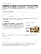
If your heater has been installed correctly, operating
the heater is an easy task. The upper front panel of the
heater contains the control center that allows you to
turn the heater On or Off and adjust the temperature
settings for the pool or spa. The temperature range is
factory set from 50°F (18°C) to 104°F (40°C). See fig-
ure above for location of toggle switch to turn the
heater On and Off. Section 4 of this manual contains
more details about the use of the controls in the
Control Adjustments subsection (page 34).
OFF
ON
SECTION 1 - START-UP PROCEDURE
1. Clean air louvers of dust, lint and debris.
2. Keep heater area clear and free from com-
bustibles, flammable liquids and chemicals.
3. Verify that the flow of combustion and ventilation
air is not obstructed.
4. Water must be flowing through the heater during
operation. Ensure that the system is filled with
water and the pump is operating. Double check
for any water leaks.
5. Purge air from the gas line. Insufficient purging
may keep the heater from lighting on the first try.
6. Double check gas connections, make sure no
leaks are present. Use soapy water to inspect.
7. Double check incoming electrical power, verify suf-
ficient output voltage to the heater.
8. The unit comes wired for 240V/1ph/60Hz power. If
the supply voltage is nominally 120V/1ph/60Hz,
switch the blower harness located inside the cabi-
net (see wiring diagram).
9. If installed indoors, make sure flue gases are vent-
ed properly, and that combustion and makeup air
openings are adequate.
10. Locate and turn the gas valve ON.
11. Locate the plugged bleedle valve off the right side
of the gas valve.
12. Remove the bleedle plug and connect a manome-
ter to the valve.
13. Locate and flip the display lid upwards.
14. Turn the heater on, by pressing the ON/OFF tog-
gle switch on the front display.
15. Set the mode to either SPA or POOL.
16. If the set point is higher than the current tempera-
ture, the heater will begin its startup sequence.
17. The ignition control will verify that the blower air
switch is open before starting the blower. Once
proven open, the blower will be powered to start
the ignition sequence. Verify suction pressure
matches the table below, Blower Suction
Pressure, for your model heater during the pre-
purge period.
18. Once the blower air switch proves, a 45 second
pre-purge period will begin to purge residual
gases from the combustion chamber.
Model Elevation Blower Suction
259B
0-2000 ft. -3.5 to -3.8 "WC
2000-5000 ft. -3.1 to -3.6 "WC
5000-7000 ft. -2.8 to -3.2 "WC
409B
0-2000 ft. -3.7 to -4.0 "WC
2000-5000 ft. -3.3 to -3.8 "WC
5000-7000 ft. -3.0 to -3.4 "WC
Table A: Blower Suction Pressure
Fig. 1: Control Center

6
SECTION 3 - MAINTENANCE AND
CARE PROCEDURES
To be followed one month after start-up and then semi-
annually.
1. Inspect and operate all controls, gas valve and
pressure relief valve.
2. On indoor heaters, clean room intake openings to
ensure adequate flow of combustion and ventila-
tion air.
3. Keep area around heater clear and free from com-
bustible materials, gasoline and other flammable
and corrosive vapors and liquids.
IF HEATER WILL NOT FIRE:
If you have no electrical power, it may be that your
"circuit breaker" has tripped. Try re-setting it.
If you have electrical power but the heater will not fire
check the following or see Troubleshooting section:
1. The time clock must be in the "ON" position.
2. Your pump strainer basket may be full. If so
remove debris.
3. Your filter may be dirty. If so, backwash or clean
filter. (To tell if your filter is dirty, look to see if the
filter pressure will be higher than usual).
4. The pump may have lost its prime and be running
dry. Check the pressure on the filter. If there is no
pressure; then you are not moving water (or your
gauge is broken). Try to get the pump to run at its
normal flow rate.
CAUTION: Combustion air must not be contaminat-
ed by corrosive chemical fumes which can damage
the heater and void the warranty.
WARNING: Check the heater for possible rodent
nests after long periods of non-use.
SECTION 2 - CAUTION
Elevated water temperature can be hazardous. The
U.S. Consumer Product Safety Commission has these
guidelines:
1. Spa water temperatures should never exceed
104°F (40°C). A temperature of 100°F (38°C) is
considered safe for a healthy adult. Special caution
is suggested for young children.
2. Drinking of alcoholic beverages before or during
spa or hot tub use can cause drowsiness which
could lead to unconsciousness and subsequently
result in drowning.
3. Pregnant Women Beware! Soaking in water over
102°F (39°C) can cause fetal damage during the
first three months of pregnancy resulting in the birth
of a brain-damaged or deformed child. Pregnant
women should stick to the 100°F (38°C) maximum
rule.
4. Before entering the spa or hot tub, users should
check the water temperature with an accurate ther-
mometer; spa or hot tub thermostats may err in reg-
ulating water temperatures by as much as 4°F
(2.2°C).
19. Once the pre-purge period ends, the igniter will
begin to spark just prior to the gas valve opening.
The gas valve will open for a 4 second trial for igni-
tion. If flame is proven, the heater will operate to
meet heat demand. If flame is not proven, the
heater will enter a post-purge period and then retry
the ignition cycle or lockout, depending on the
heater configuration.
20. Once gas is flowing, the manometer reading will
drop to -0.40” +/- .1” WC. See the instructions on
page 40 for adjusting the valve manifold pressure
if the reading is not within tolerance.
21. Visually check through the sight glass that the
heater is on and heating. A yellowish glow coming
from the refractory indicates that the heater is run-
ning. The flame should be a blueish color.
22. Remove the manometer and replace with bleedle
plug.
23. Reinstall front door panel and knurled screw hold-
ing the door in place.
24. Feel the inlet and outlet pipes. Outlet pipe should
be only slightly warmer than the inlet. It should not
be hot.
5. Persons with a medical history of heart disease, cir-
culatory problems, diabetes, or blood pressure
problems should obtain a physician's advice before
using pools or hot tubs.
6. Persons taking medications which induce drowsi-
ness, such as tranquilizers, antihistamines, or anti-
coagulants, should not use spas or hot tubs.

7
CAUTION: Propane gas is heavier than air and will settle on the ground. Since propane can accumulate in
c
onfined areas, extra care should be exercised when lighting propane heaters.
W
ARNING: Should overheating occur or the gas supply fail to shut off, turn off the manual gas control to the
heater.
L
ighting & Shutdown Instructions
Fig. 2: Lighting & Shutdown Instructions

8
Chemical imbalance can cause severe damage to
y
our heater and associated equipment. Maintain
your water chemistry according to the chart on page 2.
If the mineral content and dissolved solids in the water
become too high, scale forms inside the heat exchang-
er tube, reducing heater efficiency and damaging the
heater. If the pH drops below 7.2, this will cause cor-
rosion of the heat exchanger and severely damage the
heater. Heat exchanger damage resulting from
chemical imbalance is not covered by the warran-
ty.
All chemicals must be introduced and completely dilut-
ed into the pool or spa water before being circulated
through the heater. Do not place sanitizing chemicals
in the skimmer. High chemical concentrations will
result when the pump is not running (e.g. overnight).
Chlorinators must feed downstream of the heater and
have an anti-siphoning device to prevent chemical
back-up into the heater when the pump is shut off. A
check valve should be installed between the heater
outlet and the chlorinator.
See plumbing diagrams on page 30 and 31.
NOTE: High chemical concentrates from feeders and
chlorinators that are out of adjustment will cause rapid
corrosion to the heat exchanger. Such damage is not
covered under the warranty.
COLD WEATHER OPERATION
IMPORTANT FREEZE INFORMATION
COLD CLIMATE: Prolonged operation with water
temperatures below 50°F is not recommended.
W
hen starting the heater with water temperatures
below 50°F, operate the heater continuously until
higher temperatures are reached. Operating the
heater for prolonged periods with pool water below
50°F can seriously damage the heater, and is not cov-
ered by the warranty.
For freezing climate areas, please follow the winteriz-
ing procedures listed.
WINTERIZING THE POOL & SPA HEATER
Heaters installed outdoors in freezing climate areas
may be shut down for the winter. Observe the following
procedure for winterizing the heater:
1. Turn off gas valve, manual gas valve, and electrical
supply to the heater.
2. Open the drain valve located on the inlet/outlet
header (at the lowest point). Pull the PRV handle
upwards to allow air in while the water drains
through the valve.
POOL & SPA WATER CHEMISTRY
AUTOMATIC CHLORINATORS AND
CHEMICAL FEEDERS
MODERATE CLIMATE: Heater operation can contin-
ue during short-term cold spells. When temperatures
are between 0°F and 32°F, flow (continuous pump
operation) must be maintained.
CAUTION: Do not use the heater to maintain water
temperatures just above freezing or for freeze protec-
tion. When heater is used during freezing weather,
care must be taken to avoid freeze-ups. Continuous
pump operation is a must. Additional protection may
be required. The heater is not warranted against
freeze-ups.

9
PART TWO
INSTALLATION AND SERVICE INSTRUCTIONS
SECTION 1 - RECEIVING EQUIPMENT
The manufacturer recommends that this manual be reviewed thoroughly before installing your pool/spa heater.
If there are any questions that this manual does not answer, please contact the factory or your local represen-
t
ative.
On receipt of your equipment it is suggested that you visually check for external damage to the carton. If the
carton is damaged, a note should be made on the Bill of Lading when signing for the equipment. Remove the
heater from the carton. If it is damaged, report the damage to the carrier immediately. Save the carton.
These items are shipped inside a box in the carton with the heater:
STANDARD UNIT
1. (1) Plastic Pipe Finish Flange for Gas Line 9. (2) 3-1/2” Vinyl Grommets
2. (1) Bonding Lug with Mounting Screw 10. (1) 2” CPVC Slip Tee
3. (3) 2” CPVC Slip x Slip Nipples 11. (1) 2” x 1” CPVC Slip x FPT Bushing
4. (2) 2” CPVC Slip x MPT Adapters 12. (1) Flow Switch with Paddle
5. (2) 2” CPVC Buttress Tail Pieces 13. (1) Flow Switch Cover
6. (2) O-Rings 14. (1) IOI Manual
7. (2) 2” CPVC Slip Tail Pieces 15. (2) Warranty Documentation
8. (2) 2” CPVC Ring Nuts 16. (1) ASME Data Certification
Be sure that you receive the number of packages indicated on the Bill of Lading.
When ordering parts, you must specify the model and serial numbers of the heater. See below for location of
serial number. When ordering under warranty conditions, you must also specify date of installation.
Fig. 3: Loose Parts
Fig. 4: Unit Identification

10
SECTION 3 - INSTALLATION INSTRUCTIONS
IMPORTANT NOTICE
These instructions are intended only for the use by qualified personnel, specifically trained and experi-
enced in the installation of this type of heating equipment and related system components. Installation
and service personnel may be required by some states to be licensed. If your state is such, be sure your con-
tractor bears the appropriate license. Persons not qualified shall not attempt to fix this equipment nor attempt
repairs according to these instructions.
WARNING: Improper installation, adjustment, alteration, service or maintenance may damage the equip-
ment, create a hazard resulting in asphyxiation, explosion or fire, and will void the warranty.
CODE REQUIREMENTS
NOTE: The heater should not be located in an area where possible water leakage will result in damage to the
area adjacent to the heater or to the structure. When such locations cannot be avoided, it is recommended that
a suitable drain pan, with adequate drainage, be installed under the heater. The pan must not restrict combustion
air flow.
Installation must be in accordance with local codes, or, in the absence of local codes, with the latest edition of
the National Fuel Gas Code, ANSI Z223.1/NFPA54 and National Electrical Code, ANSI/NFPA 70, and for
Canada, the latest edition of CAN/CSA-B149 Installation Codes, and Canadian Electrical Code, CSA C22.1
Part1 and Part 2.
SECTION 2 - GENERAL SPECIFICATIONS
These heaters are design-certified and tested under the latest requirements of the ANSI Z21.56 / CSA 4.7
Standard for Gas-Fired Pool Heaters. Each heater has been constructed and pressure-tested in accordance
with the requirements of Section IV Part HLW of the American Society of Mechanical Engineers Code, and fac-
tory fire-tested.
All models are National Board registered. Temperature and pressure gauge is standard. Direct Spark ignition
device is standard. All heaters can be used either indoor or outdoors.
Ambient Temperature Rating of Heater Components
Electronic Ignition Heater* -32°F to + 175°F
*Requires 120 or 240VAC Single-Phase 60 Hertz Power Supply
Rated inputs are suitable for up to 2,000 feet elevation. The input will be reduced by approximately 4% for each
1,000 feet above 2,000 feet, as high elevation reduces gas and air density.
WARNING: This unit contains refractory ceramic fiber (RCF) insulation in the combustion chamber. RCF, as
manufactured, does not contain respirable crystalline silica. However, following sustained exposure to very
high temperatures (>2192°F), the RCF can transform into crystalline silica (cristabolite). The International
Agency for Research on Cancer (IARC) has classified the inhalation of crystalline silica (cristabolite) as car-
cinogenic to humans.
When removing the burner or heat exchanger, take precautions to avoid creating airborne dust and avoid
inhaling airborne fibers. When cleaning spills, use wet sweeping or High Efficiency Particulate Air (HEPA)
filtered vacuum to minimize airborne dust. Use feasible engineering controls such as local exhaust ventilation
or dust collecting systems to minimize airborne dust. Wear appropriate personal protective equipment
including gloves, safety glasses with side shields, and appropriate NIOSH certified respiratory protection, to
avoid inhalation of airborne dust and airborne fiber particles.

11
OUTDOOR HEATER INSTALLATION
These heaters are design-certified for outdoor installation, when equipped with the approved tops designated for
outdoor use.
WARNING: The heater shall not be located in an area where water sprinklers, or other devices, may cause
water to spray through the cabinet louvers and into the heater. This could cause internal rusting or damage
electrical components, and void the warranty.
WARNING: Do not install within 3 feet of a heat pump or an outdoor condensing unit. Strong air intake from
this type of equipment can disturb the combustion process and cause damage or personal injury.
CLEARANCES
ALL HEATERS
F
or clearances from combustible surfaces, see the
chart below.
CLEARANCE FROM
C
OMBUSTIBLE CONSTRUCTION
INDOOR INSTALLATIONS:
Top* - 30” Back - 1”
Front - Alcove (Open) Right Side - 1”
Vent - 1” Left Side - 1”
Floor** - 0”
OUTDOOR INSTALLATION - TOP EXHAUST
Top* - Unobstructed (Outdoor Stack)
Floor - 0” Right Side - 8”
Back - 6” Left Side - 8”
OUTDOOR INSTALLATION - REAR EXHAUST
Top* - Unobstructed
Floor - 0” Right Side - 8”
Back - 12” Left Side - 8”
*Clearance from top of vent terminal when using top
vent. When using the rear vent, top clearance is
reduced to 1”..
**Do not install on carpeting.
W
hen installed according to the listed minimum clear-
ances from combustible construction, the pool heater
can still be serviced without removing permanent
construction around the heater.
However, for ease of servicing, Raypak recom-
mends a clearance of at least 24” in the front, at
least 18" on the water connection side and 12” on
top. This will enable the heater to be serviced in its
installed location, that is, without movement or
removal of the heater.
Clearances to combustible surfaces can be reduced
per Table 10.2.3 of the National Fuel Gas Code.
The heater must be installed in a manner that will
enable the heater to be serviced without removing any
structure around the heater.
FLOORING: This heater can be installed on com-
bustible flooring. Do not install on carpet.
Table B: Combustible Clearances

12
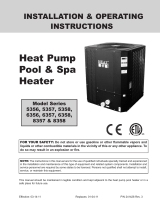
Heaters must not be installed under an overhang of less than three 3 ft from the top of the heater. Three sides
must be open in the area under the overhang. Roof water drainage must be diverted away from the heaters
installed under overhangs with the use of gutters.
For U.S. installations, the point from where the flue products exit the heater must be a minimum of 4 ft below,
4 ft horizontally from, or 1 ft above any door, window or gravity inlet into any building. The top surface of the
heater shall be at least 3 ft above any forced air inlet, or intake ducts located within 10 ft horizontally.
F
or installations in Canada, pool heaters shall not be installed with the top of the vent assembly within 10 ft
below, or to either side, of any opening into the building. Refer to the latest revisions of CAN/CSA-B149.
4 ft
Minimum
4 ft
Minimum
1 ft
Minimum
4 ft
Minimum
3 ft
Minimum
10 ft
Minimum
Forced Air Inlet
For installations in Florida and Texas, that must comply with the Florida or Texas Building Code, follow the
directions on page 13 for the installation of hurricane tie-down method for all models.
Fig. 5: Outdoor Installation Clearances

13
Florida Building Code
Fig. 6: Florida Building Code 2010 Tie-Down Method

14
INDOOR HEATER INSTALLATION
Locate the heater as close as is practical to a chimney or gas vent. The heater must always be vented to the
o
utside. See the Venting section (beginning on page 17) for details. Minimum allowable clearance is shown on
the nameplate, and in the “Clearances” section on page 11. Adequate combustion and ventilation air must be
p
rovided. See page 16 for details.
Notes:
1. The model number prefix indicates: (B=Bronze header), (R=Raypak) Model number suffix indicates: pilot
type (E = digital) and fuel type (P = propane, N = natural gas) fin tubing (X=Cupro-Nickel, C= Copper).
Example: Model number BR-409B-EN-X indicates a unit with digital (IID) ignition using natural gas with
bronze headers and cupro-nickel tubes.
2. Ratings are for natural gas and elevations up to 2,000 feet above sea level. For elevations over 2,000 feet,
consult the factory.
3. Flue gases must be properly vented with CAT I vertical venting or CAT III horizontal venting. Non-metallic
venting not acceptable. Inlet air can be ducted with 4” metal or PVC pipe. See the venting section of this
manual for complete venting details.
ELECTRICAL REQUIREMENTS:
120V/1ph/60Hz 6A
2
40V/1ph/60Hz 3A
*
SPECIFICATIONS AND DIMENSIONS
Heater
Model
MBTU
Input
Dimensions (in.)
Shipping
Weight (lbs)
w/ Stackless
Top
Flue
Diameter
(B)
Air Inlet
(C)
Minimum
Flow
(gpm)
Maximum
Flow
(gpm)
BR-259B 250.0 6” 4” 25 125 193
BR-409B 399.0 6” 4” 40 125 205
* Rear vent addon option 016256 required for rear exhaust location.
Fig. 7: Unit Dimensions

15
U.S. Installations
1
Canadian Installations
2
A
Clearance above grade, veranda, porch,
deck, or balcony
1 ft (30 cm) 1 ft (30 cm)
B
Clearance to window or door that may be
opened
4 ft (1.2m) below or to side
of opening; 1 foot (30 cm)
above opening
3 ft (91 cm)
C Clearance to permanently closed window * *
D
Vertical clearance to ventilated soffit located
above the terminal within a horizontal dis-
tance of 2 ft (61cm) from the centerline of the
terminal
5 ft (1.5m) *
E Clearance to unventilated soffit * *
F Clearance to outside corner * *
G Clearance to inside corner 6 ft (1.83m) *
H
Clearance to each side of center line ex-
tended above meter/regulator assembly
*
I Clearance to service regulator vent outlet * 3 ft (91cm)
J
Clearance to non-mechanical air supply inlet
to building or the combustion air inlet to any
other appliance
4 ft (1.2m) below or to side
of opening; 1 ft (30 cm)
above opening
3 ft (91 cm)
K Clearance to mechanical air supply inlet
3 ft (91 cm) above if within
10 ft (3m) horizontally
6 ft (1.83m)
L
Clearance above paved sidewalk or paved
driveway located on public property
7 ft (2.13m)
7 ft (2.13m) t
M
Clearance under veranda, porch, deck or
balcony
* 12 in. (30 cm) TT
1
In accordance with the current ANSI Z223.1/NFPA 54 National Fuel Gas Code
2
In accordance with the current CAN/CSA-B149 Installation Codes
t Vent terminal shall not terminate directly above sidewalk or paved driveway located between 2 single family dwellings that se rves
both dwellings
TT Permitted only if veranda, porch, deck, or balcony is fully open on a minimum of two sides beneath the floor and top of term inal and
underside of veranda, porch, deck or balcony is greater than 1 ft (30cm)
* Clearances in accordance with local installation codes and the requirements of the gas supplier
3 ft (91 cm) within a
height 15 ft above the
meter/regulator assembly
Minimum Clearances from Vent/Air Inlet Terminations – Indoor and Outdoor Installations
Fig. 8: Vent/Air Inlet Termination Clearances

16
B. All Air From Outdoors:
When air is supplied directly from outside the building, each opening shall have a minimum net free area
as noted:
C
OMBUSTION AND VENTILATION AIR (Indoor Units Only)
The heater must have both combustion and ventilation air. Minimum requirements for net free air supply open-
ings are one opening that is 12 inches from the ceiling for ventilation, and one opening that is 12 inches from
the floor for combustion air as outlined in the latest edition of the National Fuel Gas Code, ANSI Z223.1(Canada-
C
AN/CSA-B149) and any local codes that may have jurisdiction.
CAUTION: Combustion air must not be contaminated by corrosive chemical fumes which can damage the
heater and void the warranty.
A. All Air From Inside The Building:
Each opening shall have a minimum net free area as noted:
Model Square Inches
259B 250
409B 399
Model
Unrestricted Opening (sq. in.)
Typical Screened or
Louvered Opening (sq. in.)
Typical Screened and
Louvered Opening (sq. in.)
259B 63 95 126
409B 100 150 200
Direct Vent and Ducted Combustion Air Systems
If outside air is drawn through the intake pipe directly to the unit for combustion:
1. Connect combustion air to the heater by removing the screen on the air intake port, and sliding the PVC
adapter to the shoulder. Glue or attach screws to fasten. The existing screen is used at the intake end of the
duct. Install the combustion air duct in accordance with page 21 (horizontal) or page 22 (vertical) of this man-
ual.
2. Provide adequate ventilation of the space occupied by the heater(s) by an opening(s) for ventilation air at
the highest practical point communicating with the outdoors.
a) In the US, the total cross-sectional area shall be at least 1 in.
2
of free area per 20,000 BTUH (111 mm
2
per kW) of total input rating of all equipment in the room when the opening is communicating directly
with the outdoors or through vertical duct(s). The total cross-sectional area shall be at least 1 in.
2
of free
area per 10,000 BTUH (222 mm
2
per kW) of total input rating of all equipment in the room when the
opening is communicating with the outdoors through horizontal duct(s).
b) In Canada, there shall be permanent air supply opening(s) having a total cross-sectional area of not less
than 1 in.
2
of free area per 30,000 BTUH (70 mm
2
per kW) of the total rated input. The location of the
opening(s) shall not interfere with the intended purpose of the opening(s) for the ventilation air.
3. In cold climates, and to mitigate potential freeze-up, Raypak highly recommends the installation of a motor-
ized sealed damper to prevent the circulation of cold air through the heater during the non-operating hours.
Table C-1: Combustible Air Opening Size
Table C-2: Combustible Air Opening Size

17
General
Appliance Categories
Heaters are divided into four categories based on the
pressure produced in the exhaust and the likelihood of
condensate production in the vent.
Category I – A heater which operates with a non-pos-
itive vent static pressure and with a vent gas tempera-
ture that avoids excessive condensate production in
the vent.
Category II – A heater which operates with a non-pos-
itive vent static pressure and with a vent gas tempera-
ture that may cause excessive condensate production
in the vent.
CAUTION: Proper installation of flue venting is
c
ritical for the safe and efficient operation of the
heater.
NOTE: For additional information on appliance
categorization, see appropriate ANSI Z21 Standard
and the NFGC (U.S.), or B149 (Canada), or
applicable provisions of local building codes.
WARNING: Contact the manufacturer of the vent
material if there is any question about the appliance
categorization and suitability of a vent material for
application on a Category III or IV vent system.
Using improper venting materials can result in
personal injury, death or property damage.
VENTING
Table D: Venting Category Requirements
Combustion
Air Supply
Exhaust
Configuration
Heater
Venting
Category
Certified
Materials
Combustion Air
Inlet Materials
From Inside Building
Vertical
Venting
I
Fan
B-Vent
Equivalent
Horizontal
Through-the-Wall
Venting
III
UL 1738
Metallic Vent
(such as AL29-4C)
From Outside Building
(Direct Vent or
Ducted Combustion Air)
Vertical Venting
with Ducted
Combustion Air
I
Fan
B-Vent
Equivalent
Galvanized Steel
PVC
ABS
CPVC
Vertical
Direct Vent
III
UL 1738
Metallic Vent
(such as AL29-4C)
Horizontal
Direct Vent
III
UL 1738
Metallic Vent
(such as AL29-4C)
C
ategory III – A heater which operates with a positive
vent pressure and with a vent gas temperature that
a
voids excessive condensate production in the vent.
Category IV – A heater which operates with a positive
vent pressure and with a vent gas temperature that
may cause excessive condensate production in the
vent.
See the table below for appliance category require-
ments.

18
Support of Vent Stack
T
he weight of the vent stack or chimney must not rest
on the heater vent connection. Support must be pro-
v
ided in compliance with applicable codes. The vent
should also be installed to maintain proper clearances
from combustible materials. Use insulated vent pipe
spacers where the vent passes through combustible
r
oofs and walls.
Vent Terminal Location
1. Condensate can freeze on the vent cap. Frozen
condensate on the vent cap can result in a blocked
flue condition.
2. Give special attention to the location of the vent
termination to avoid possibility of property dam-
age or personal injury.
3. Gases may form a white vapor plume in winter.
The plume could obstruct a window view if the ter-
mination is installed near windows.
4. Prevailing winds, in combination with below-freez-
ing temperatures, can cause freezing of conden-
sate and water/ice build-up on buildings, plants or
roofs.
5. The bottom of the vent terminal and the air intake
shall be located at least 12 in. above grade, includ-
ing normal snow line.
6. Un-insulated single-wall metal vent pipe shall not
be used outdoors in cold climates for venting gas-
fired equipment.
7. Through-the-wall vents for Category II and IV
appliances and non-categorized condensing appli-
ances shall not terminate over public walkways or
over an area where condensate or vapor could
create a nuisance or hazard or could be detrimen-
tal to the operation of regulators, relief valves, or
other equipment. Where local experience indi-
cates that condensate is a problem with Category
I and III appliances, this provision shall also apply.
8. Locate and guard vent termination to prevent acci-
dental contact by people or pets.
9. DO NOT terminate vent in window well, stairwell,
alcove, courtyard or other recessed area.
NOTE: During winter months check the vent cap
and make sure no blockage occurs from build-up of
snow or ice.
10. DO NOT terminate above any door, window, or
gravity air intake. Condensate can freeze, causing
ice formations.
11. Locate or guard vent to prevent condensate from
damaging exterior finishes. Use a rust-resistant
sheet metal backing plate against brick or mason-
ry surfaces.
12. DO NOT extend exposed vent pipe outside of
building beyond the minimum distance required
for the vent termination. Condensate could freeze
and block the vent pipe.
U.S. Installations
Refer to the latest edition of the National Fuel Gas
Code.
Vent termination requirements are as follows:
1. Vent must terminate at least 4 ft below, 4 ft hori-
zontally from or 1 ft above any door, window or
gravity air inlet to the building.
2. The vent must not be less than 7 ft above grade
when located adjacent to public walkways.
3. Terminate vent at least 3 ft above any forced air
inlet located within 10 ft.
4. Vent must terminate at least 4 ft horizontally, and
in no case above or below unless 4 ft horizontal
distance is maintained, from electric meters, gas
meters, regulators, and relief equipment.
5. Terminate vent at least 6 ft away from adjacent
walls.
6. DO NOT terminate vent closer than 5 ft below roof
overhang.
7. The vent terminal requires a 12 in. vent terminal
clearance from the wall.
8. Terminate vent at least 1 ft above grade, including
normal snow line.
9. Multiple direct vent installations require a 4 ft
clearance between the ends of vent caps located
on the same horizontal plane.
WARNING: The Commonwealth of Massachusetts
requires that sidewall vented heaters, installed in
every dwelling, building or structure used in whole or
in part for residential purposes, be installed using
special provisions as outlined on page 47 of this
manual.

19
Canadian Installations
R
efer to latest edition of the B149 Installation code.
A vent shall not terminate:
1. Directly above a paved sidewalk or driveway
which is located between two single-family dwell-
ings and serves both dwellings.
2. Less than 7 ft (2.13 m) above a paved sidewalk or
paved driveway located on public property.
3. Within 6 ft (1.8 m) of a mechanical air supply inlet
to any building.
4. Above a meter/regulator assembly within 3 ft (915
mm) horizontally of the vertical centre-line of the
regulator.
5. Within 3 ft (0.9 m) of any gas service regulator
vent outlet.
6. Less than 1 ft (305 mm) above grade level.
7. Within the 3 ft (915 mm) of a window or door which
can be opened in any building, any non-mechani-
cal air supply inlet to any building or the combus-
tion air inlet of any other appliance.
8. Underneath a verandah, porch or deck, unless the
verandah, porch or deck is fully open on a mini-
mum of two sides beneath the floor, and the dis-
tance between the top of the vent termination and
the underside of the verandah, porch or deck is
greater than 1 ft (305 mm).
Venting Installation Tips
Support piping:
• horizontal runs—at least every 5 ft
• vertical runs—use braces
• under or near elbows
Venting Configurations
For heaters connected to gas vents or chimneys, vent
installations shall be in accordance with the NFGC
(U.S.), or B149 (Canada), or applicable provisions of
local building codes.
Natural Draft Vertical Venting
(Category I) Fan-Assisted
Installation
Natural draft venting uses the natural tendency of the
heated flue gases to rise, until they are expelled from
the top of the flue. The negative draft must be within
the range of -.01 to -.08 in. WC as measured 12 in.
above the appliance flue outlet to ensure proper oper-
ation. Vent material must be listed by a nationally rec-
ognized test agency.
Double-wall Type B vent must be used to promote
draft and to minimize condensation in the vent.
No drafthood is required or offered. A single-acting
barometric damper is required if the height exceeds 25
feet. Consult the factory for additional information.
WARNING: Examine the venting system at least
once a year. Check all joints and vent pipe
connections for tightness, corrosion or deterioration.
Table E: Category I Vertical Venting
1
Vent lengths are based on a lateral length of 2 ft. Refer to the latest edition of the NFGC for further
details. When vertical height exceeds 25 ft, consult factory prior to installation.
* Subtract 10 ft per elbow. Max. 4 elbows.
** Schedule 40 in PVC or CPVC.
Model
No.
Certified
Vent
Material
Vent Size
(in.)
Vertical Vent
Height
1
(ft)
Combustion Air
Intake Pipe
Material**
Air Inlet
Max. Length*
(ft)
4” Ø
Min. Max.
259B
Category I
(Type B
Equivalent)
Fan-Assisted
6 5 25
Galvanized Steel,
PVC,
ABS,
CPVC
80
409B

20
Horizontal Through-the-Wall Venting
(Category III)
Fig 10: Horizontal Through-the-Wall Venting
Fig. 9: Vertical Venting
CAUTION: This venting system requires the
installation of a condensate drain in the vent piping
per the vent manufacturer’s instructions. Failure to
install a condensate drain in the venting system will
void all warranties on this heater.
Installation
These installations utilize the heater’s internal blower
to vent the combustion products to the outdoors.
Combustion air is taken from inside the room and the
vent is installed horizontally through the wall to the out-
doors. Adequate combustion and ventilation air must
be supplied to the equipment room in accordance with
the NFGC (U.S.) or B149 (Canada).
The total length of the horizontal through-the-wall flue
system should not exceed 80 equivalent ft in length. If
horizontal run exceeds 80 equivalent ft, an appropri-
ately sized variable-speed extractor must be used.
Each elbow used is equal to 10 ft of straight pipe. This
will allow installation in one of the five following
arrangements:
• 80’ of straight flue pipe
• 70’ of straight flue pipe and one elbow
• 60’ of straight flue pipe and two elbows
• 50’ of straight pipe and three elbows
• 40’ of straight pipe and four elbows
The vent cap is not considered in the overall length of
the venting system.
The connection from the appliance vent to the stack
must be as direct as possible. The horizontal breach-
ing of a vent must have an upward slope of not less
t
han 1/4 inch per linear foot from the heater to the vent
terminal. The horizontal portions of the vent shall also
be supported for the design and weight of the material
employed to maintain clearances and to prevent phys-
ical damage or separation of joints.
Termination
The vent terminal should be vertical and should termi-
nate outside the building at least 2 ft above the highest
point of the roof that is within 8 ft. The vent cap should
have a minimum clearance of 4 ft horizontally from and
in no case above or below (unless a 4 ft hori-zontal
distance is maintained) electric meters, gas meters,
regulators and relief equipment. The distance of the
vent terminal from adjacent public walkways, adjacent
buildings, open windows and building openings must
be consistent with the NFGC (U.S.) or B149 (Canada).
Gas vents supported only by flashing and extended
above the roof more than 5 ft should be se-curely
guyed or braced to withstand snow and wind loads.
VENT CAP
8
NOTE: For common venting of two or more heaters,
contact the factory.
CAUTION: A listed vent cap terminal adequately
sized, must be used to evacuate the flue products
from the building.
/