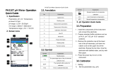
Hanna Instruments HI2221-01 Owner's manual

Category
Measuring, testing & control
Type
Owner's manual

This manual is also suitable for

1
Instruction Manual
HI2221 - HI2223
pH/mV/ºC
Bench Meters
with Calibration Check
www.hannainst.com
2
Dear Customer,
Thank you for choosing a Hanna Instruments product.
Please read this instruction manual carefully before using these
instruments.
This manual will provide you with the necessary information for correct
use of these instruments, as well as a precise idea of their versatility.
If you need additional technical information, do not hesitate to e‑mail
us at [email protected] or view our worldwide contact list at
www.hannainst.com.
All rights are reserved. Reproduction in whole or in part is prohibited
without the written consent of the copyright owner.
3
PRELIMINARY EXAMINATION ..........................................................4
GENERAL DESCRIPTION .................................................................. 4
FUNCTIONAL DESCRIPTION .............................................................5
HI2221 SPECIFICATIONS ...............................................................6
HI2223 SPECIFICATIONS ...............................................................7
OPERATIONAL GUIDE .....................................................................8
pH CALIBRATION .........................................................................10
ENHANCED CALIBRATION MESSAGES ............................................14
ELECTRODE CONDITION AND ELECTRODE RESPONSE TIME ..............16
pH BUFFER TEMPERATURE DEPENDENCE ......................................17
GOOD LABORATORY PRACTICE (GLP) ..............................................18
LOGGING .....................................................................................21
SETUP ........................................................................................24
TEMPERATURE CALIBRATION (for technical personnel only) .............27
mV CALIBRATION (for technical personnel only) ..............................29
PC INTERFACE .............................................................................30
ELECTRODE CONDITIONING AND MAINTENANCE ............................. 34
TROUBLESHOOTING GUIDE ..........................................................37
TEMPERATURE CORRELATION FOR pH SENSITIVE GLASS ................. 38
ACCESSORIES .............................................................................. 39
TABLE OF CONTENTS
4
Remove the instrument from the packing material and examine it carefully
to make sure that no damage has occurred during shipping. If there is any
damage, please contact your local Hanna Instruments Office.
Each instrument is supplied complete with:
HI1131P Glass‑body Combination pH Electrode with 1 m
(3.3“) cable
HI7662 Temperature Probe
HI76404N Electrode Holder
pH4.01 & 7.01 Buffer Solutions (20 mL each)
HI7082 Electrolyte Solution
HI700661 Cleaning Solutions (20 mL each)
12 VDC Power Adapter
Instruction Manual
Quality Certificate
Note: Save all packing material until you are sure that the instrument
functions correctly. All defective items must be returned in the
original packing with the supplied accessories.
HI2221 and HI2223 are logging microprocessor‑based pH/ORP/
temperature bench meters with Calibration Check.
Calibration Check performs a set of diagnostic tests during calibration
using the history of electrode slope and offset to detect problems that
can cause loss of accuracy.
Calibration Check Features are:
Enhanced Calibration Messages
During calibration the user is warned if one or more parameters
are not suitable to perform an accurate calibration.
Electrode Condition on LCD Display
Determined from the electrode offset and slope.
Electrode response time on LCD Display
Determined from electrode performance during calibration.
Other features include: up to five pH point calibration with seven mem
orized buffers (1.68, 4.01, 6.86, 7.01, 9.18, 10.01 and 12.45 pH),
logging up to 100 samples (for HI2221) and 500 samples (for HI2223),
GLP, calibration due alarm, pH reading with manual or automatic
temperature compensation and PC software interface.
PRELIMINARY EXAMINATION
GENERAL DESCRIPTION
5
FUNCTIONAL DESCRIPTION
Front Panel
Rear Panel
1) Liquid Crystal Display (LCD).
2) CAL key, to enter and exit calibration mode.
3) CFM/GLP key, to confirm calibration, different values or to display
Good Laboratory Practice information.
4) °C key, to manually increase temperature value or other
parameters.
5) °C key, to manually decrease temperature value or other
parameters.
6) SETUP key, to enter/exit SETUP mode.
7) RANGE key, to select measurement range, switch to focused data
in SETUP or to toggle between buffer value and temperature during
calibration.
8) LOG/CLR key, to store a value into memory, to clear pH calibration,
or to delete log records.
9) RCL key, memory recall.
10) ON/OFF switch.
11) Power supply socket.
12) USB connector.
13) BNC electrode connector.
14) Temperature probe socket.
15) Electrode reference socket.
6
HI2221 SPECIFICATIONS
Range
–2.00 to 16.00 pH
±699.9 mV
±2000 mV
–20.0 to 120.0 °C (‑4.0 to 248.0 °F)
Resolution
0.01 pH
0.1 mV (±699.9 mV)
1 mV (±2000 mV)
0.1 °C
Accuracy
@ 20 °C/68 °F
±0.01 pH
±0.2 mV (±699.9 mV)
±1 mV (±2000 mV)
±0.2 °C (excluding probe error)
Calibration Check Yes
Computer Interface Opto‑isolated USB
pH Calibration
Automatic up to 5 points, 7 buffers available
(1.68, 4.01, 6.86, 7.01, 9.18, 10.01, 12.45)
Logging 100 points
Temperature
Compensation
Manual or Automatic from:
–20.0 to 120.0 °C (–4.0 to 248.0 °F)
pH Electrode
HI1131P glass body, double junction refillable
cell, BNC + pin (included)
Temperature Probe HI7662 stainless steel probe (included)
Input Impedance 10
12
ohm
Power Supply 12 VDC adapter (included)
Environment
0 – 50 °C (32 ‑– 122 °F)
max RH 95 % non condensing
Dimensions 235 x 222 x 109 mm (9.2 x 8.7 x 4.3”)
Weight
1.3 Kg (2.9 lb);
kit with holder 2.1 Kg (4.6 lb)
Warranty 2 years
7
HI2223 SPECIFICATIONS
Range
–2.00 to 16.00 pH
–2.000 to 16.000 pH
±999.9 mV
±2000 mV
–20.0 to 120.0 °C (‑4.0 to 248.0 °F)
Resolution
0.01 pH
0.001 pH
0.1 mV (±999.9 mV)
1 mV (±2000 mV)
0.1 °C
Accuracy
@ 20 °C/68 °F
±0.01 pH
±0.002 pH
±0.2 mV (±999.9 mV)
±1 mV (±2000 mV)
±0.2 °C (excluding probe error)
Calibration Check Yes
Computer Interface Opto‑Isolated USB
pH Calibration
Automatic up to 5 points, 7 buffers available
(1.68, 4.01, 6.86, 7.01, 9.18, 10.01, 12.45)
Logging 500 points
Temperature
Compensation
Manual or Automatic from:
–20.0 to 120.0 °C (–4.0 to 248.0 °F)
pH Electrode
HI1131P glass body, double junction refillable
cell, BNC + pin (included)
Temperature Probe HI7662 stainless steel probe (included)
Input Impedance 10
12
ohm
Power Supply 12 VDC adapter (included)
Environment
0 – 50 °C (32 – 122 °F)
max RH 95 % non condensing
Dimensions 235 x 222 x 109 mm (9.2 x 8.7 x 4.3”)
Weight
1.3 Kg (2.9 lb);
kit with holder 2.1 Kg (4.6 lb)
Warranty 2 years
8
OPERATIONAL GUIDE
POWER CONNECTION
Plug the 12 VDC adapter into the power supply socket.
Notes: • These instruments use non volatile memory to retain
the pH, mV, temperature calibrations and all other settings, even
when unplugged.
• Make sure a fuse protects the mains line.
ELECTRODE AND PROBE CONNECTIONS
For Hanna Instruments P Type pH or ORP electrodes (with internal
reference) connect the electrode’s BNC to the socket on the back of the
instrument and the pin to the reference socket.
Note: Electrode condition and response information is displayed on
the bar graph gauges during the day the calibration is performed,
only if Hanna Instruments P type (PIN) electrodes are used.
If the electrode is not recognized as a Hanna Instruments P type
electrode, the bar graph gauges will blink (25 seconds OFF,
4 seconds ON, full bar graph).
For temperature measurement and automatic temperature compensation
connect the temperature probe to the appropriate socket.
INSTRUMENT START-UP
Turn the instrument on by pressing the ON/OFF switch located on
the rear panel.
All LCD tags are displayed and a beep is sounded while the instrument
performs a self test.
The instrument will display “LoAD” message and “
” blinking until
initialization is complete.
The “Unscrew electrode refilling cap” message reminds the user to
loosen or remove the electrode refilling cap to improve the electrode’s
response time.
The instrument automatically defaults to pH measurement mode
unless a Hanna Instruments P type ORP electrode is detected.
pH MEASUREMENT
Make sure the instrument has been calibrated before
taking pH measurements.
Submerse the tip of a properly conditioned
electrode (see page 34) and the temperature
9
RANGE
probe approximately 3 cm (1¼”) into the sample to be tested and stir
gently. Allow time for the electrode to stabilize.
The pH is displayed on the primary LCD and the temperature on the
secondary LCD.
The pH reading is out of range, the closest full‑scale value will be
displayed blinking on the primary LCD.
If measurements are taken successively in different samples, it is recom
mended to rinse the electrode thoroughly with deionized water or tap wa
ter and then with some of the next sample to prevent cross‑contamination.
The pH reading is affected by temperature. In order to measure the pH
accurately, this temperature effect must be compensated for. To use the
Automatic Temperature Compensation feature, connect and submerse
the HI7662 temperature probe into the sample as close
to the electrode as possible and wait for a few minutes.
If the temperature of the sample is known, manual
compensation can be performed by disconnecting the
temperature probe.
The display will show the last recorded temperature
reading with the “°C” symbol blinking.
The temperature can now be adjusted with the ARROW keys (from
‑20.0 ºC to 120.0 ºC).
ORP MEASUREMENTS
An optional ORP electrode must be used to perform ORP measurements
(see Accessories).
Oxidation‑Reduction Potential (REDOX) measurements provide the
quantification of the oxidizing or reducing power of the tested sample.
The surface of the ORP electrode must be clean and smooth in order to
obtain an accurate measurement.
10
Calibrate the instrument frequently, especially if high accuracy is required.
For best results and constant display of electrode condition and electrode
response on the bar graph gauges, daily calibration is recommended.
The instrument should be recalibrated:
Whenever the pH electrode is replaced.
At least once a day.
After testing aggressive chemicals.
If high accuracy is required.
If “CAL DUE” message is displayed during measurement.
Every time you calibrate the instrument use fresh buffers and perform an
electrode cleaning procedure (see page 36).
PREPARATION
Pour small quantities of the buffer solutions into clean beakers. If possible,
use plastic or glass beakers to minimize any EMC interferences.
For accurate calibration and to minimize cross‑contamination, use two
beakers for each buffer solution. One for rinsing the electrode and one
for calibration.
pH CALIBRATION
Pretreatment solutions are available to condition the
electrode and speed up the response time.
The instrument automatically defaults to the
mV measurement mode if Hanna Instruments
P type ORP electrode is detected.
• Submerse the ORP electrode tip (3 cm (1¼”) into the sample. Allow
a few minutes for the reading to stabilize.
The instrument displays the mV reading on the primary LCD.
• If the reading is out of range, the closest full‑scale value will be
displayed blinking on the primary LCD.
TAKING TEMPERATURE MEASUREMENTS
Connect the HI7662 temperature probe and turn the
instrument on. Dip the temperature probe into the sample
and allow the reading on the secondary LCD to stabilize.
11
PROCEDURE
Calibration can be performed up to five points. For accurate measurements
a three point calibration is recommended. Calibration can be performed
using the seven memorized buffers:
pH1.68, 4.01, 6.86, 7.01, 9.18, 10.01 and 12.45.
FIVE-POINT CALIBRATION
For most applications it is recommended that pH7.01 or 6.86 buffers
be used as the first calibration point and pH4.01 (for acidic samples) or
pH9.18/10.01 (for alkaline samples) as the second calibration point.
Note: The pH12.45 buffer is not for general measurement; use only
if the sample is very alkaline to avoid sodium error.
Submerse the pH electrode and the temperature probe approximately
3 cm (1¼”) into a buffer solution and stir gently. The temperature
probe should be close to the pH electrode.
Press the CAL key. “CAL” and “pH” tags will be on, and the “CLEAR
CAL if new electrode” tag will blink.
Press the CLR key if you are using a new electrode or want to clear
the calibration history. The instrument will display the “donE
message for a few seconds.
Press the CAL key, or wait a few seconds to continue.
It is very important to clear the calibration history when a new electrode
is used because all error and warning messages that appear during
calibration depend on the calibration history.
Notes: • The “CLEAR CAL if new electrode” will only appear if
the instrument has been previously calibrated.
• The “CAL”, “pH” and “BUFFER” tags will appear and the “7.01
buffer will be displayed on the secondary LCD.
• If necessary, press the ARROW keys to select a different buffer
value.
• The “
” tag will blink until the reading has stabilized.
12
GL P
CF M
GL P
CF M
When the reading is stable and close to the selected buffer, the “CFM
tag will blink and if enabled, an audible signal will sound.
Press the CFM key to confirm the calibration. The calibrated value
will be displayed on the primary LCD and the second expected buffer
value on the secondary LCD.
After the first calibration point is confirmed, submerse the pH electrode
and the temperature probe approximately 3 cm (1¼”) into the second
buffer solution and stir gently. The temperature probe should be close
to the pH electrode.
If necessary, press the ARROW keys to select a different buffer value.
Note: The instrument will automatically skip the buffer used for
the first point. It also skips 6.86 if 7.01 was used, and vice versa.
Likewise, it will skip 9.18 if 10.01 has been used, and vice versa.
The “ ” tag will blink on the LCD until the reading is stable.
When the reading is stable and close to the selected buffer the “CFM
tag will blink.
Press CFM to confirm calibration.
The calibrated value is then displayed on the
primary LCD and the third expected buffer value
on the secondary LCD.
After the second calibration point is confirmed, submerse the pH
electrode and the temperature probe approximately 3 cm (1¼”)
into the next buffer solution and stir gently. The temperature probe
should be close to the pH electrode.
If necessary, press the ARROW keys to select a different buffer value.
The “ ” tag will blink on the LCD until the reading is stable.
When the reading is stable and close to the selected buffer the “CFM
tag will blink.
Press CFM to confirm calibration.
After the third calibration point is confirmed,
submerse the pH electrode and the temperature
probe approximately 3 cm (1¼”) into the next
buffer solution and stir gently. The temperature probe should be
close to the pH electrode.
If necessary, press the ARROW keys to select a different buffer value.
The “ ” tag will blink on the LCD until the reading is stable.
13
GL P
CF M
GL P
CF M
RANGE
When the reading is stable and close to the selected buffer the “CFM
tag will blink.
Press CFM to confirm calibration.
After the fourth calibration point is confirmed,
submerse the pH electrode and the temperature
probe approximately 3 cm (1¼”) into the next buffer
solution and stir gently. The temperature probe should be close to
the pH electrode.
If necessary, press the ARROW keys to select a different buffer value.
The “ ” tag will blink on the LCD until the reading is stable.
When the reading is stable and close to the selected buffer the “CFM
tag will blink.
Press CFM to confirm calibration.
The instrument stores the calibration value and
returns to normal measurement mode.
FOUR, THREE OR TWO-POINT CALIBRATION
Proceed as described in “FIVE‑POINT CALIBRATION” section.
• Press CAL after the fourth, third or second calibration point was
confirmed. The instrument will memorize the calibration data and
return to measurement mode.
ONE-POINT CALIBRATION
Two SETUP selectable options are available: “Pnt” and “OFFS”.
If the “Pnt” option is selected, the new calibration point overrides an
existing one. The adjacent slopes will be reevaluated.
If the “OFFS” option is selected, an electrode offset correction is
performed.
The adjacent slopes will remain unchanged.
Proceed as described in “FOUR, THREE or TWO‑POINT CALIBRATION”
section.
• Press CAL after the first calibration point was confirmed. The
instrument will memorize the one‑point calibration data and return
to measurement mode.
Notes: To clear calibration parameters for all uncalibrated buffers
starting with current buffer, press CLR. The calibration will continue
from the current point. If this procedure is performed while calibrating
in the first calibration point, the instrument returns to measurement
mode.
Press RANGE to toggle between pH buffer,
calibration buffer number and temperature
reading.
14
The stored calibration history is used to issue error and warning messages
during calibration to help ensure the highest accuracy.
As electrode aging is normally a slow process, substantial changes
from previous calibrations are likely due to a temporary problem
with the electrode or buffers.
ERROR MESSAGES
Error messages appear if one or all of the calibration parameters are
out of accepted windows. Calibration can not continue when these errors
are displayed.
WRONG BUFFER
This message appears when the difference between the pH reading and the
value of the selected buffer is too large. If this error message is displayed,
check if you have selected the proper calibration buffer.
CLEAN ELECTRODE
This error message indicates a bad electrode condition (offset out of
accepted window, or slope under the accepted lower limit).
Clean the electrode according to the Cleaning Procedure on page 36 to
improve its condition and repeat the calibration. This ensures the removal
of film, dirt or deposits on the glass bulb and reference junction.
CHECK ELECTRODE alternating with CHECK BUFFER
This error message appears when electrode slope exceeds the highest
accepted slope limit. You should check your electrode and use fresh buffer.
ELECTRODE
This message appears if the cleaning procedure performed as a result of
the above two messages is found by the instrument to be unsuccessful.
ENHANCED CALIBRATION MESSAGES
15
Replace the electrode.
BUFFER TEMPERATURE
This message appears if the temperature of the buffer is outside the
defined buffer temperature range.
WARNING MESSAGES
During calibration, the Calibration Check feature analyzes the electrode
calibration history and warns the user when problems have been detected.
It is possible to override the warning messages and confirm the calibration
but it is not recommended.
CLEAN ELECTRODE
This warning appears during Calibration Check for the second calibration
buffer when the instrument has detected a small variation of offset or
both offset and slope parameters. This variation may result from dirt on
the electrode. Refer to the electrode cleaning procedure. This ensures the
removal of film, dirt or deposits on the glass bulb and reference junction.
CLEAN ELECTRODE alternating with CHECK BUFFER
This warning appears during Calibration Check in the first calibration buffer
as a result of unacceptable offset variation or in the second calibration
buffer as a result of unacceptable slope variation. This variation may result
from dirt on the electrode or contaminated buffer. Refer to the electrode
cleaning procedure or use fresh buffer.
CONTAMINATED BUFFER
This warning message appears in order to alert that the buffer could be
contaminated. Refresh your buffer and continue the calibration procedure.
16
When using an appropriate Hanna Instruments P Type BNC electrode with
pin, HI2221 and HI2223 will assess electrode condition and response
time during each calibration, the calibration status is displayed for the
rest of the day.
The response gauge is a function of the stabilization time between the first
and second calibration buffers. These gauges reflect electrode performance
and should be expected to slowly decrease over the life of the electrode.
The condition gauge shows the electrode’s condition at the time of
calibration.
For a continuous display of electrode condition and response, daily cali
bration is necessary. This information can also be viewed in the GLP data.
If the instrument is not calibrated, the calibration history was deleted,
or it has been calibrated only at one point, the electrode condition and
the electrode response gauges will be empty.
When the instrument cannot evaluate the electrode response, the response
gauge will be empty (pH1.68 or pH12.45 were used).
If the electrode is in a very poor condition the first condition segment
will blink.
If electrode response is very slow the first response segment will blink.
ELECTRODE CONDITION AND
ELECTRODE RESPONSE TIME
17
pH BUFFER TEMPERATURE
DEPENDENCE
The temperature has an effect on pH. The calibration buffer solutions are
affected by temperature changes to a lesser degree than normal solutions.
During calibration the instrument will automatically calibrate to the pH
value corresponding to the measured or set temperature.
During calibration the instrument will display the pH buffer value at 25 ºC.
TEMP pH BUFFERS
°C °F 1.68 4.01 6.86 7.01 9.18 10.01 12.45
0 32 1.67 4.01 6.98 7.13 9.46 10.32 13.38
5 41 1.67 4.00 6.95 7.10 9.39 10.24 13.18
10 50 1.67 4.00 6.92 7.07 9.33 10.18 12.99
15 59 1.67 4.00 6.90 7.05 9.27 10.12 12.80
20 68 1.68 4.00 6.88 7.03 9.22 10.06 12.62
25 77 1.68 4.01 6.86 7.01 9.18 10.01 12.45
30 86 1.68 4.02 6.85 7.00 9.14 9.96 12.29
35 95 1.69 4.03 6.84 6.99 9.11 9.92 12.13
40 104 1.69 4.04 6.84 6.98 9.07 9.88 11.98
45 113 1.70 4.05 6.83 6.98 9.04 9.85 11.83
50 122 1.71 4.06 6.83 6.98 9.01 9.82 11.70
55 131 1.72 4.08 6.84 6.98 8.99 9.79 11.57
60 140 1.72 4.09 6.84 6.98 8.97 9.77 11.44
65 149 1.73 4.11 6.84 6.99 8.95 9.76 11.32
70 158 1.74 4.12 6.85 6.99 8.93 9.75 11.21
75 167 1.76 4.14 6.86 7.00 8.91 9.74 11.10
80 176 1.77 4.16 6.87 7.01 8.89 9.74 11.00
85 185 1.78 4.17 6.87 7.02 8.87 9.74 10.91
90 194 1.79 4.19 6.88 7.03 8.85 9.75 10.82
95 203 1.81 4.20 6.89 7.04 8.83 9.76 10.73
18
GOOD LABORATORY PRACTICE (GLP)
GLP is a set of functions that allows the storage and retrieval of data
regarding the maintenance and status of the electrode.
All data regarding the last calibration is stored for the user to review
when necessary.
EXPIRED CALIBRATION
These instruments allow the user to set the number of days before the
next required calibration. This value can be set from 1 to 7 days. The
default setting is OFF (disabled).
The “CAL DUE” tags will blink to warn the user that the instrument
should be recalibrated.
For example, if a 4 days time out has been selected, the instrument will
issue the alarm exactly 4 days after the last calibration.
If the expiration value is changed (e.g. to 5 days), then the alarm will
be immediately recalculated and appear 5 days after the last calibration.
Notes: • If the instrument was not calibrated, or if the calibration
history was deleted, the “CAL DUE” message will be displayed even
if this feature is disabled in the SETUP menu.
• If the instrument was calibrated using an electrode with pin and
the electrode is changed with an electrode without pin or vice‑versa,
CAL DUE will blink. This feature helps ensure use of a calibrated
instrument.
pH CALIBRATION DATA
Calibration data is stored automatically after a successful calibration.
To view the pH calibration data, press the GLP key when the instrument
is in pH measuring mode.
The instrument will display the time of the last calibration.
Use the ARROW keys to scroll through the calibration data:
The time (hh:mm).
The date (yyyy / mm.dd).
19
The pH calibration offset.
The pH calibration slope in mV/pH normalized to 25 °C (the per
centage is referred to the ideal value of 59.16 mV/pH).
Note: If you calibrate using electrodes with pin, the electrode
condition and response gauges appear while the offset and slope
are displayed.
The pH calibration buffers in calibrating order and with the selected
resolutions used during calibration.
The first pH calibration buffer:
The second pH calibration buffer:
The third pH calibration buffer:
The fourth pH calibration buffer:
The fifth pH calibration buffer:
Note: The “OLd” message displayed beside the pH value means that
this buffer was not used during last calibration. Press and hold down
SETUP if you want to see calibration date (or time, if old calibration
was performed on the same day as the current calibration).
20
If “no bUF” message appears on the LCD, the instrument informs
you that the calibration was performed with less than five buffers.
Calibration Expiration status:
‑ if disabled,
‑ or the number of days until the calibration alarm will be displayed,
‑ or if expired (7 days ago).
The instrument ID.
Notes: • Press GLP to return to measurement mode.
• If calibration has not been performed, the instruments
display “no CAL” message blinking.
  • Page 1 1
  • Page 2 2
  • Page 3 3
  • Page 4 4
  • Page 5 5
  • Page 6 6
  • Page 7 7
  • Page 8 8
  • Page 9 9
  • Page 10 10
  • Page 11 11
  • Page 12 12
  • Page 13 13
  • Page 14 14
  • Page 15 15
  • Page 16 16
  • Page 17 17
  • Page 18 18
  • Page 19 19
  • Page 20 20
  • Page 21 21
  • Page 22 22
  • Page 23 23
  • Page 24 24
  • Page 25 25
  • Page 26 26
  • Page 27 27
  • Page 28 28
  • Page 29 29
  • Page 30 30
  • Page 31 31
  • Page 32 32
  • Page 33 33
  • Page 34 34
  • Page 35 35
  • Page 36 36
  • Page 37 37
  • Page 38 38
  • Page 39 39
  • Page 40 40
  • Page 41 41
  • Page 42 42
  • Page 43 43
  • Page 44 44

Hanna Instruments HI2221-01 Owner's manual

Category
Measuring, testing & control
Type
Owner's manual
This manual is also suitable for

Ask a question and I''ll find the answer in the document

Finding information in a document is now easier with AI