
1
BATTERY OPERATED HYDRAULIC CRIMPING TOOL
OUTIL HYDRAULIQUE DE SERTISSAGE SUR BATTERIE
HYDRAULISCHES AKKU-PRESSWERKZEUG
HERRAMIENTA HIDRÁULICA DE CRIMPADO A BATERÍA
UTENSILE OLEODINAMICO DA COMPRESSIONE A BATTERIA
B1350-C B1350-CA B1350-CE B1350-CT
ENGLISH
FRANÇAIS
DEUTSCH
ESPAÑOL
ITALIANO
OPERATION AND MAINTENANCE MANUAL ................................................. 5
NOTICE D’UTILISATION ET ENTRETIEN ......................................................... 13
BEDIENUNGSANLEITUNG ................................................................................. 21
MANUAL DE USO Y MANTENIMIENTO .........................................................29
MANUALE D’USO E MANUTENZIONE ...........................................................37
19 M 238

2
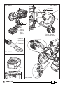
FIG. / BILD 1 FIG. / BILD 2
FIG. / BILD 3
FIG. / BILD 4
FIG. / BILD 5
4
5
7
14
P
Connector
Connecteur
Kabelschuh
Conector
Connettore
Battery
Batterie
Akku
Batería
Batteria
Die set - Matrices -
Presseinsätze - Matrici
12
13
11
~ 15 ÷ 20 mm
(0.6 - 0.8
in.)
15

3
1 + 3
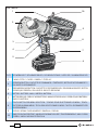
LED WORKLIGHT / ECLAIRAGE PAR LED / LED-BELEUCHTUNG / LUCES LED / ILLUMINAZIONE LED
2
C-HEAD / TETE C / C-KOPF / CABEZA C / TESTA A C
4
OPERATING BUTTON / GACHETTE DE COMMANDE / STARTKNOPF / BOTÓN DE ACCIONAMIENTO /
PULSANTE DI AZIONAMENTO
5
PRESSURE RELEASE BUTTON / GACHETTE DE DECOMPRESSION / DRUCKABLASSKNOPF / BOTÓN
DESBLOQUEO PRESIÓN / PULSANTE DI SBLOCCO PRESSIONE
6
BATTERY / BATTERIE / AKKU / BATERÍA / BATTERIA
7
BATTERY RELEASE /
DEBLOCAGE BATTERIE / AKKU ENTRIEGELUNG / DESBLOQUEO BATERÍA /
SBLOCCO BATTERIA
8
TOUCH BUTTON FOR MENU SELECTION / TOUCHE POUR SELECTIONNER LE MENU / TOUCH-
TASTE FÜR AUSWAHLMENÜ / TECLA PARA SELECCIONAR EL MENÚ / TASTO A SFIORAMENTO PER
SELEZIONE MENU
9
DISPLAY / ECRAN / DISPLAYANZEIGE / PANTALLA / DISPLAY
10
RING FOR SHOULDER STRAP / ANNEAU POUR BANDOULIERE / TRAGERIEMENRING / ANILLO PARA
CORREA / ANELLO AGGANCIO TRACOLLA
FIG. / BILD 6
3
10
4
5
6
7
8
9
2
1
Page is loading ...

5
(1)
Directive 2006/42/EC, annexe 1, point 1.7.4.2 letter u
L
pA
= weighted continuous acoustic pressure level equivalent.
L
pCPeak
= maximum value of the weighted acoustic displacement pressure at the work place.
L
WA
= acoustic power level emitted by the machine.
(2)
Directive 2006/42/EC, annexe 1, point 2.2.1.1
Weighted root mean square in frequency of the acceleration the upper limbs are exposed to for each biodynamic
reference axis. Tests carried out in compliance with the indications contained in EN ISO 5349-1/2 Standard, and under
operating conditions much more severe than those normally found.
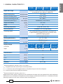
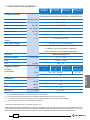
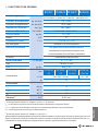
1. GENERAL CHARACTERISTICS
ENGLISH
B1350-C B1350-CE B1350-CT B1350-CA
Application range suitable for installing electrical compression connectors
on conductors up to 400 mm
2
(800 MCM)
Rated crimping force
kN (US sh. ton)
132 (14.84)
Minimum crimping force
kN (US sh. ton)
125,2 (14.07)
Minimum operating pressure
bar (psi) 692 (10037)
Dimensions (ref. to Fig. 7) mm (inches) 338x344x83 (13.3x13.5x3.3)
Weight with battery kg (lbs) 6,5 (14.3)
Motor V DC 18
Operating temperature °C (°F) -15 to +50 (+5 to +122)
Recommended oil ENI ARNICA ISO 32 or equivalents
Operating speed twin speed operation and automatic switching from
a rapid advancing speed of the ram to a slower, more
powerful crimping speed
Safety maximum pressure valve
Rechargeable battery V / Ah / Wh 18 / 5.2 / 93.6
Type CB1852L (Li-Ion)
Weight kg (lbs) 0,66 (1.45)
Battery charger
ASC30-36
Input
type
ASC30-36-
EU
ASC30-36-
UK
ASC30-36-
AUS/NZ
ASC30-36-
USA/CAN
V / Hz 220 - 240 / 50 - 60 115 / 60
W 85
Acoustic noise
(1)
L
pA
dB (A)
73
L
pCPeak
dB (C) 94.5
L
WA
dB (A) 79
Vibration
(2)
m/s
2
0.575 max.

6
ENGLISH
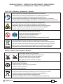
WARNING
Do not use the tool for purposes other than those intended by Cembre.
The operator should concentrate on the work being performed and be careful to maintain
a balanced working position.
Before starting work on electrical equipment, please ensure that either there are no live
parts in the immediate working area or that precautions are taken for working near live
parts in accordance with EN50110-1.
Do not use this tool on or near energised conductors without proper personal protective
equipment. Failure to observe this warning could result in severe injury or death.
The tool is unsuitable for continuous use and should be allowed to cool down following
uninterrupted, successive crimping operations; for instance, having exhausted a fully charged
battery in one session, delay battery replacement for a few minutes.
Protect the tool from rain and moisture. Water will damage the tool and battery. Electro-
hydraulic tools should not be operated in pouring rain.
2. INSTRUCTIONS FOR USE
IMPORTANT: Never pressurise the tool without inserting the dies, this could cause damage
to the head and the ram.
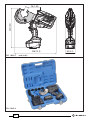
The part reference includes the following (Ref. to Fig. 8 page 45):
Hydraulic crimping tool.
Li-Ion rechargeable battery (2 pcs).
Battery charger (model depends on the tool version).
Shoulder strap.
Plastic carrying case.
USB cable (Ref. to § 5).
2.1) Preparation
The tool can be easily carried using either the handle or the shoulder strap attached to ring (10)
(Ref. to Fig. 6).
Before starting any work, check the battery charge (Ref. to § 2.8) and recharge if necessary,
following the instructions in the battery charger user manual.

7
ENGLISH
1
2
1
2
2
1
terminal
connector
conductor
conductor
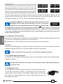
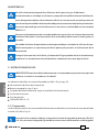
To replace the battery, remove it by pressing the release button (7) (Ref. to Fig. 1), then insert the
new battery, sliding it into the guides until it locks.
The display shows the operational parameters of the tool; to customise them proceed as described
in § 2.7.
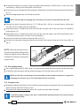
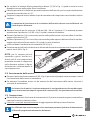
Select the appropriate die set for the connector.
When introducing or changing dies, the battery must rst be removed from the tool.
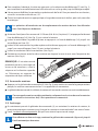
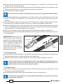
Operate the tool to advance the ram (11) 15-20 mm (0.6 - 0.8 in.) so to easily press release pin
(14) (Ref. to Fig. 2) then remove the battery.
Keep release pin (14) depressed and insert one die into the seat on the ram until it is locked by
retaining pin (15).
Keep release pin (12) depressed and insert one die into the upper seat of the tool head until it
is locked by retaining pin (13) then insert the battery.
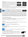
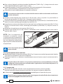
Insert the conductor into the connector (Ref. to Fig. 3).
Position the connector between the dies and ensure the correct location of the crimp (Ref. to
Fig. 4).
NOTE: when more compression is
required, proceed according to the
sequence and direction indicated
in the gure, uniformly spacing the
compressions.
2.2) Die advancement
Press operating button (4) (Ref. to Fig. 4) to activate the motor-pump and advance the lower die.
To halt the advancement, release operating button (4) and the motor will cut out.
Make sure the dies are exactly positioned on the desired crimp point otherwise re-open dies
following instructions as per § 2.4 and reposition the connector.
2.3) Compression
By keeping operating button (4) pressed, the motor continues to operate: the ram will gradually
move forward until the two dies touch.
The motor will stop automatically when the set pressure has been reached.
To perform proper compression, press and hold the operating button (4) until the motor
stops automatically.

8
ENGLISH
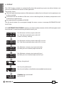
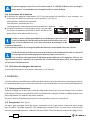
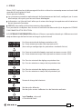
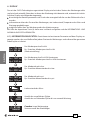
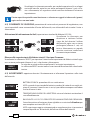
NOTE: To display the momentary force or pressure during
the work cycle, select the appropriate display from the
menu (Ref. to § 4). When the operating button is released
before the motor stops automatically, the display will show
the peak force (Fp) or the peak pressure (Pp) reached at
that instant.
To complete the work, press the operating button again until the motor stops automatically; the display
will show the maximum force or pressure reached followed by "OK" to conrm correct operation.
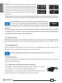
The display "ERROR", combined with a beep and the LEDs ashing, indi-
cates an incorrect crimping procedure caused by the work cycle being
interrupted before the control parameters (force/pressure) of the tool are
reached.
This error appears when the pressure release button has been operated and the tool has already
reached a pressure >100 bar. In this case, repeat the compression by pressing and holding the op-
erating button until the motor stops automatically.
2.4) Release of dies
By operating the pressure release button (5) (Ref. to Fig. 4), the ram will retract and open the dies.
To take the dies o their guide, sliding them pushing the release pins (12 and 14) (Ref. to Fig. 2).
2.5) LED Worklights
Whilst the tool is in operation, the compression area is illuminated by two high luminosity LED
Worklights that switch o automatically at the end of the cycle.
The LED Worklights can be disabled by following the procedure described in § 4.2.
2.6) Head rotation
For ease of operation, the tool head can rotate through 180°, allowing the operator to work in the
most comfortable position.
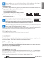
2.7) Capacitive touch button for menu selection
This button is located under the display and allows selection of various
screens (Ref. to § 4); it only works when the display is on.
Wearing gloves or using other objects may inhibit the operation of the
button, therefore use a bare nger to apply only a light touch.
B1350
13AB485
RESET
SW:S1J41413
LED
OFF
Fm = 125.2 kN
Fp = 94.5 kN
F
m = 14.07 ton
Fp = 10.61 ton
1000
-29000
BATTERY
3 SEC.
ERROR
001
30001
BATTERY
Fm = 125.2 kN
F
p = 102.3 kN
P
m = 692 bar
P
p = 565 bar
F
m = 125.2 kN
OK
P
m = 692 bar
OK
P
m = 10037 psi
Pp = 7575 psi
002
003
BATTERY
004
LED
ON
LED
OFF
3 SEC.
LED
ON
max.
BATTERY BATTERY
min.
Pm = 692 bar
Pp = 522.3 bar
B1350
13AB485
RESET
SW:S1J41413
LED
OFF
Fm = 125.2 kN
Fp = 94.5 kN
F
m = 14.07 ton
Fp = 10.61 ton
1000
-29000
BATTERY
3 SEC.
ERROR
001
30001
BATTERY
Fm = 125.2 kN
F
p = 102.3 kN
Pm = 692 bar
P
p = 565 bar
Fm = 125.2 kN
OK
Pm = 692 bar
OK
Pm = 10037 psi
Pp = 7575 psi
002
003
BATTERY
004
LED
ON
LED
OFF
3 SEC.
LED
ON
max.
BATTERY BATTERY
min.
Pm = 692 bar
Pp = 522.3 bar
B1350
13AB485
RESET
SW:S1J41413
LED
OFF
Fm = 125.2 kN
Fp = 94.5 kN
F
m = 14.07 ton
Fp = 10.61 ton
1000
-29000
BATTERY
3 SEC.
ERROR
001
30001
BATTERY
Fm = 125.2 kN
Fp = 102.3 kN
P
m = 692 bar
Pp = 565 bar
F
m = 125.2 kN
OK
P
m = 692 bar
OK
P
m = 10037 psi
Pp = 7575 psi
002
003
BATTERY
004
LED
ON
LED
OFF
3 SEC.
LED
ON
max.
BATTERY BATTERY
min.
Pm = 692 bar
Pp = 522.3 bar

9
ENGLISH
B1350
13AB485
RESET
SW:S1J41413
LED
OFF
Fm = 125.2 kN
Fp = 94.5 kN
F
m = 14.07 ton
Fp = 10.61 ton
1000
-29000
BATTERY
3 SEC.
ERROR
001
30001
BATTERY
Fm = 125.2 kN
F
p = 102.3 kN
P
m = 692 bar
P
p = 565 bar
F
m = 125.2 kN
OK
P
m = 692 bar
OK
P
m = 10037 psi
Pp = 7575 psi
002
003
BATTERY
004
LED
ON
LED
OFF
3 SEC.
LED
ON
max.
BATTERY BATTERY
min.
Pm = 692 bar
Pp = 522.3 bar
Do not apply pressure to or stab at the touch button, a light touch using a bare nger is
sucient. The command pulse is sent when the nger releases the button.
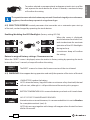
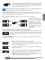
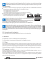
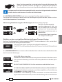
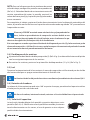
2.8) Battery status
The battery is equipped with LED indicators that indicate the remaining battery life at any time
by pressing the adjacent button (P) (Ref. to Fig. 5):
4 LEDs illuminated: fully charged
2 LEDs illuminated: 50 % capacity
1 LED flashing: minimum charge, replace the battery.
With the battery inserted into the tool, the remaining
battery life can also be checked on the display, via touch
button selection (Ref. to § 4).
The screen shown alongside indicates that the battery voltage has
dropped below a minimum safety threshold; under these conditions
the tool will not start,and it is necessary to recharge or replace the bat
tery. The approximate time to fully recharge a battery is about 100 miutes.
After each working cycle, and after the extraction of the battery from the tool, an integrated
battery cut-o device will operate after 70 s approx.
Then the LED nearest to button (P) will ash 5 times each 14 s approx. The battery will be
reactivated when it is reintroduced into the tool and the operating button is pressed.
2.9) Using the battery charger
Carefully follow the instructions in the battery charger user manual.
3. MAINTENANCE
The tool is robust, completely sealed, and requires very little daily maintenance. Compliance with
the following points, should help to maintain its optimum performance:
3.1) Thorough cleaning
Dust, sand and dirt are a danger for any hydraulic device.
Every day, after use, the tool must be wiped with a clean cloth taking care to remove any residue,
especially close to pivots and moveable parts.
Do not use hydrocarbons to clean the rubber parts.
3.2) Storage case (Ref. to Fig. 8)
When not in use, the tool should be stored and transported in the plastic case, to prevent damage.
The case, type VAL P39, is suitable for storing the tool, the accessories and up to 8 die sets and pre-
prepared compression connectors.
VAL P39: Size 520x432x126 mm (20.5x17.0x5.0 inches). Weight 2,6 kg (5.7 lbs).
B1350
13AB485
RESET
SW:S1J41413
LED
OFF
Fm = 125.2 kN
Fp = 94.5 kN
F
m = 14.07 ton
Fp = 10.61 ton
1000
-29000
BATTERY
3 SEC.
ERROR
001
30001
BATTERY
Fm = 125.2 kN
F
p = 102.3 kN
P
m = 692 bar
P
p = 565 bar
F
m = 125.2 kN
OK
P
m = 692 bar
OK
P
m = 10037 psi
Pp = 7575 psi
002
003
BATTERY
004
LED
ON
LED
OFF
3 SEC.
LED
ON
max.
BATTERY BATTERY
min.
Pm = 692 bar
Pp = 522.3 bar

10
ENGLISH
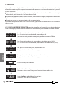
4. DISPLAY
The OLED display switches on automatically when the operating or pressure release buttons are
pressed, and o after 60 seconds of non-operation.
The display shows:
The main operational parameters of the tool processed by the circuit board, such as peak pressure
or force reached.
Information on the condition of the tool, such as the charge level, the battery temperature and
maintenance requirements.
Any operational or procedural ERRORS.
Use the touch button (8) to navigate through the menu screens to manage INFORMATION AND
SELECTION:
4.1) INFORMATION SCREENS: display a pre determined parameter which will then appear each
time the tool is started and during the entire work cycle.
B1350
13AB485
RESET
SW:S1J41413
LED
OFF
Fm = 125.2 kN
Fp = 94.5 kN
Fm = 14.07 ton
Fp = 10.61 ton
1000
-29000
BATTERY
3 SEC.
ERROR
001
30001
BATTERY
Fm = 125.2 kN
F
p = 102.3 kN
P
m = 692 bar
P
p = 565 bar
Fm = 125.2 kN
OK
P
m = 692 bar
OK
Pm = 10037 psi
Pp = 7575 psi
002
003
BATTERY
004
LED
ON
LED
OFF
3 SEC.
LED
ON
max.
BATTERY BATTERY
min.
Pm = 692 bar
Pp = 522.3 bar
Fm: Minimum set force, expressed in kN.
Fp: Peak force reached, expressed in kN.
(screen as factory setting)
Fm: Minimum set force, expressed in USA sh. tons.
Fp: Peak force reached, expressed in USA sh. tons.
Pm: Minimum set pressure, expressed in bar.
Pp: Peak pressure reached, expressed in bar.
Pm: Minimum set pressure, expressed in psi.
Pp: Peak pressure reached, expressed in in psi.
Battery charge level.
No. of cycles performed.
No. of cycles before scheduled recommended maintenance.
Cembre logo, tool model.
tool serial no.

11
ENGLISH
To make a selected screen operational and appear at each start-up of the
tool, operate the touch button for at least 3 seconds; a continuous beep
will conrm the setting.
The capacitive menu selection button may not work if touched using objects or when wear-
ing gloves, therefore always operate it using a bare nger.
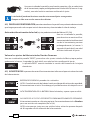
4.2) SELECTION SCREENS: control parameters that cannot be set as automatic upon start-up
of the tool, can be changed by operating the touch button:
Enabling/disabling the LED Worklights (factory setting LED ON)
When the screen is displayed,
touch the button for at least 3 sec-
onds to deactivate for reactivate
operation of the LED Worklights
during tool use;
a continuous beep will conrm
the setting.
Return to original factory settings / rmware version
When the "RESET" screen is displayed, return the tool to its factory setting by operating the touch
button for at least 3 seconds; a beep will conrm the setting.
The RESET screen also shows the rmware version of the circuit board.
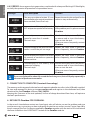
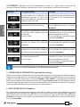
4.3) WARNINGS: these appear during operation and notify the operator of the status of the tool:
B1350
13AB485
RESET
SW:S1J41413
LED
OFF
Fm = 125.2 kN
Fp = 94.5 kN
F
m = 14.07 ton
Fp = 10.61 ton
1000
-29000
BATTERY
3 SEC.
ERROR
001
30001
BATTERY
Fm = 125.2 kN
F
p = 102.3 kN
P
m = 692 bar
P
p = 565 bar
F
m = 125.2 kN
OK
P
m = 692 bar
OK
P
m = 10037 psi
Pp = 7575 psi
002
003
BATTERY
004
LED
ON
LED
OFF
3 SEC.
LED
ON
max.
BATTERY BATTERY
min.
Pm = 692 bar
Pp = 522.3 bar
LOW BATTERY: replace the battery.
NOTE: when the battery Vage falls below a minimum safety threshold, the tool
will not start; although it is still possible to end the work cycle in progress.
BATTERY TEMPERATURE HIGH: remove the battery and wait until it cools down.
NO. OF CYCLES TO MAINTENANCE REACHED:
the tool continues to work however, it is recommended that it is sent to Cembre
for a complete overhaul (see § 6).
NOTE: this message, together with a beep, will reappear when the tool has been
idle for 30 seconds.
B1350
13AB485
RESET
SW:S1J41413
LED
OFF
Fm = 125.2 kN
Fp = 94.5 kN
F
m = 14.07 ton
Fp = 10.61 ton
1000
-29000
BATTERY
3 SEC.
ERROR
001
30001
BATTERY
Fm = 125.2 kN
F
p = 102.3 kN
P
m = 692 bar
P
p = 565 bar
F
m = 125.2 kN
OK
P
m = 692 bar
OK
P
m = 10037 psi
Pp = 7575 psi
002
003
BATTERY
004
LED
ON
LED
OFF
3 SEC.
LED
ON
max.
BATTERY BATTERY
min.
Pm = 692 bar
Pp = 522.3 bar

12
ENGLISH
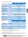
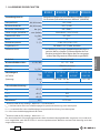
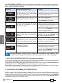
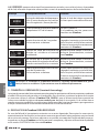
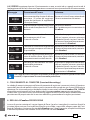
4.4) ERRORS: these appear during operation, combined with a beep and ashing LED Worklights,
to notify the operator of procedural or operational errors.
Message Error description Solution
B1300
NR 14AF035
RESET
SW:S1J41AH
LED
OFF
Fm = 125.2 kN
Fp = 94.5 kN
F
m = 14.07 ton
Fp = 10.61 ton
1000
-12000
BATTERY
3 SEC.
ERROR
001
13001
BATTERY
Fm = 125.2 kN
F
p = 102.3 kN
P
m = 692 bar
P
p = 565 bar
F
m = 125.2 kN
OK
P
m = 692 bar
OK
P
m = 10037 psi
Pp = 7575 psi
002
003
BATTERY
004
LED
ON
LED
OFF
3 SEC.
LED
ON
max.
BATTERY BATTERY
min.
Pm = 692 bar
Pp = 522.3 bar
The pressure release button (5) was
pressed before the control parameters
were reached (Force/Pressure).
Repeat the work cycle and wait for the
motor to stop automatically.
Interruption of the signal from the
NTC temperature probe of the battery.
Replace the battery.
If the problem persists, please contact
Cembre.
B1300
NR 14AF035
RESET
SW:S1J41AH
LED
OFF
Fm = 125.2 kN
Fp = 94.5 kN
F
m = 14.07 ton
Fp = 10.61 ton
1000
-12000
BATTERY
3 SEC.
ERROR
001
13001
BATTERY
Fm = 125.2 kN
F
p = 102.3 kN
P
m = 692 bar
P
p = 565 bar
F
m = 125.2 kN
OK
P
m = 692 bar
OK
P
m = 10037 psi
Pp = 7575 psi
002
003
BATTERY
004
LED
ON
LED
OFF
3 SEC.
LED
ON
max.
BATTERY BATTERY
min.
Pm = 692 bar
Pp = 522.3 bar
Abnormal power consumption of the
motor for more than 3 seconds.
The tool stops.
Wait for the display to turn o (60 sec.)
or remove and re-insert the battery,
then re-start the tool.
If the error occurs frequently, contact
Cembre.
B1300
NR 14AF035
RESET
SW:S1J41AH
LED
OFF
Fm = 125.2 kN
Fp = 94.5 kN
F
m = 14.07 ton
Fp = 10.61 ton
1000
-12000
BATTERY
3 SEC.
ERROR
001
13001
BATTERY
Fm = 125.2 kN
F
p = 102.3 kN
P
m = 692 bar
P
p = 565 bar
F
m = 125.2 kN
OK
P
m = 692 bar
OK
P
m = 10037 psi
Pp = 7575 psi
002
003
BATTERY
004
LED
ON
LED
OFF
3 SEC.
LED
ON
max.
BATTERY BATTERY
min.
Pm = 692 bar
Pp = 522.3 bar
Output voltage of the pressure trans-
mitter is out of the pre-set range.
Repeat the work cycle; if the error
occurs frequently, contact Cembre.
B1300
NR 14AF035
RESET
SW:S1J41AH
LED
OFF
Fm = 125.2 kN
Fp = 94.5 kN
F
m = 14.07 ton
Fp = 10.61 ton
1000
-12000
BATTERY
3 SEC.
ERROR
001
13001
BATTERY
Fm = 125.2 kN
F
p = 102.3 kN
P
m = 692 bar
P
p = 565 bar
F
m = 125.2 kN
OK
P
m = 692 bar
OK
P
m = 10037 psi
Pp = 7575 psi
002
003
BATTERY
004
LED
ON
LED
OFF
3 SEC.
LED
ON
max.
BATTERY BATTERY
min.
Pm = 692 bar
Pp = 522.3 bar
Failure to reach the set pressure within
30 seconds of continuous operation
of the machine.
Repeat the work cycle; if the error
occurs frequently, contact Cembre.
B1300
NR 14AF035
RESET
SW:S1J41AH
LED
OFF
Fm = 125.2 kN
Fp = 94.5 kN
F
m = 14.07 ton
Fp = 10.61 ton
1000
-12000
BATTERY
3 SEC.
ERROR
001
13001
BATTERY
Fm = 125.2 kN
F
p = 102.3 kN
P
m = 692 bar
P
p = 565 bar
F
m = 125.2 kN
OK
P
m = 692 bar
OK
P
m = 10037 psi
Pp = 7575 psi
002
003
BATTERY
004
LED
ON
LED
OFF
3 SEC.
LED
ON
max.
BATTERY BATTERY
min.
Pm = 692 bar
Pp = 522.3 bar
Overcharging of the battery with
protection tripping.
The tool stops.
Wait for the display to turn o (60 sec.)
or remove and re-insert the battery,
then re-start the tool.
If the error occurs frequently, contact
Cembre.
Errors are displayed for about 30 seconds before being reset, but will display repeatedly in
the event of permanent anomalies.
5. CONNECTION TO COMPUTER (Smartool thecnology)
The memory card integrated in the tool records operating datafor transfer via the USB cable supplied.
To view and manage this data, go to www.cembre.com and register in the dedicated area, then
download the free Cembre software CEM_SWBT01.
Keeping the Firmware of the tool updated, via free of charge download from here, will optimise
the tool’s performance.
6. RETURN TO Cembre FOR OVERHAUL
In the case of a breakdown contact our Area Agent who will advise you on the problem and give
you the necessary instructions on how to dispatch the tool to our nearest service Centre; if possible,
attach a copy of the Test Certicate supplied by Cembre together with the tool or ll in and attach
the form available in the “ASSISTANCE” section of the Cembre website.
NTC
FAULT
Page is loading ...
Page is loading ...
Page is loading ...
Page is loading ...
Page is loading ...
Page is loading ...
Page is loading ...
Page is loading ...
Page is loading ...
Page is loading ...
Page is loading ...
Page is loading ...
Page is loading ...
Page is loading ...
Page is loading ...
Page is loading ...
Page is loading ...
Page is loading ...
Page is loading ...
Page is loading ...
Page is loading ...
Page is loading ...
Page is loading ...
Page is loading ...
Page is loading ...
Page is loading ...
Page is loading ...
Page is loading ...
Page is loading ...
Page is loading ...
Page is loading ...
Page is loading ...

45
338 (13.3)
83 (3.3)
344 (13.5)
FIG. / BILD 7 mm (inch)
FIG. / BILD 8
26 (1.02)

46
– Following information applies in member states of the European Union:
– Les informations suivantes sont destinées aux pays membres del'Union Européenne:
– Die folgenden Hinweise gelten für Mitglieder der Europäischen Union:
– Las siguientes informaciones conciernen a los estados miembros de la Unión Europea:
– Le seguenti informazioni riguardano gli stati membri dell'Unione Europea:
USER INFORMATION in accordance with Directives 2011/65/EU and 2012/19/EU.
The ‘Not in the bin’ symbol above when shown on equipment or packaging means that the equipment must,
at the end of its life, be disposed of separately from other waste.
The separate waste collection of such equipment is organised and managed by the manufacturer.
Users wishing to dispose of such equipment must contact the manufacturer and follow the prescribed guide-
lines for its separate collection. Appropriate waste separation, collection, environmentally compatible treat-
ment and disposal is intended to reduce harmful environmental eects and promote the reuse and recycling
of materials contained in the equipment. Unlawful disposal of such equipment will be subject to the applica-
tion of administrative sanctions provided by current legislation.
INFORMATION POUR LES UTILISATEURS aux termes des Directives 2011/65/EU et 2012/19/EU.
Le symbole “poubelle barrée” apposé sur l’appareil ou sur son emballage indique que le produit, à la n de sa
vie utile, doit être recueilli séparément des autres déchets.
La collecte sélective du présent appareil en n de vie est organisée et gérée par le producteur. L’utilisateur
qui voudra se défaire du présent appareil devra par conséquent contacter le producteur et suivre le système
que celui-ci a adopté pour consentir la collecte séparée de l’appareil en n de vie. La collecte sélective adé-
quate pour l’envoi successif de l’appareil destiné au recyclage, au traitement et à l’élimination compatible avec
l’environnement contribue à éviter les eets négatifs possibles sur l’environnement et sur la santé et favorise la
réutilisation ou le recyclage des matériaux dont l’appareil est composé. L’élimination abusive du produit par le
détenteur comporte l’application des sanctions administratives prévues par les lois en vigueur.
INFORMATION FÜR DEN BENUTZER gemäß der Richtlinien 2011/65/EU und 2012/19/EU.
Das durchkreuzte Zeichen des Mülleimers, das auf dem Gerät oder seiner Verpackung angebracht ist, zeigt an,
dass das Produkt am Ende seiner Lebenszeit von der allgemeinen Abfallentsorgung getrennt werden muss.
Die getrennte Sammlung des vorliegenden, zu entsorgenden Gerätes, wird vom Hersteller organisiert und
verwaltet. Der Eigentümer, der das Gerät zu entsorgen wünscht, muss sich daher mit dem Hersteller in Ver-
bindung setzen und die von ihm ausgewählte Methode, für die getrennte Sammlung des zu entsorgenden
Gerätes, befolgen.
Eine angemessene getrennte Sammlung zur Vorbereitung des Altgerätes für Recycling, Aufbereitung und für
eine umweltfreundliche Entsorgung, trägt dazu bei, mögliche negative Auswirkungen auf die Umwelt und
auf den Gesundheitszustand zu vermeiden, und begünstigt die Wiederverwertung und das Recycling der
Materialien des Gerätes. Bei widerrechtlicher Entsorgung des Produktes durch den Benutzer, werden die vom
Gesetz vorgesehene Verwaltungssanktionen angewandt.
INFORME PARA LOS USUARIOS en los términos de las Directivas 2011/65/EU y 2012/19/EU.
El símbolo del contenedor de basura cruzado por un aspa que aparece en el equipo o sobre su embalaje
indica que, al nal de su ciclo de vida útil, el producto debe ser eliminado independientemente de otros dese-
chos. La recogida selectiva del presente equipo, llegado al nal de su ciclo de vida, es organizada y manejada
por el fabricante. El usuario que desee deshacerse del presente equipo deberá, por lo tanto, contactar con el
fabricante y seguir el sistema adoptado por el mismo para permitir la recogida por separado del equipo que
ha concluido su ciclo de vida. La adecuada recogida selectiva, para el sucesivo envío del equipo dado de baja
al reciclaje, al tratamiento y al saneamiento ambiental compatible, contribuye a evitar posibles efectos nega-
tivos sobre el medio ambiente y sobre la salud favoreciendo el reempleo y el reciclaje de los materiales que
componen el equipo. La eliminación abusiva del equipo por parte del propietario implica la aplicación de las
sanciones administrativas prevista por la legislación vigente.
INFORMAZIONE AGLI UTENTI ai sensi delle Direttive Europee 2011/65/EU e 2012/19/EU.
Il simbolo del cassonetto barrato riportato sull’apparecchiatura o sulla sua confezione indica che il prodotto,
alla ne della sua vita utile, deve essere raccolto separatamente dagli altri riuti.
La raccolta dierenziata della presente apparecchiatura giunta a ne vita è organizzata e gestita dal produt-
tore. L’utente che vorrà disfarsi della presente apparecchiatura dovrà quindi contattare il produttore e seguire
il sistema che questo ha adottato per consentire la raccolta separata dell’apparecchiatura giunta a ne vita.
L’adeguata raccolta dierenziata per l’avvio successivo dell’apparecchiatura dismessa al riciclaggio, al trat-
tamento ed allo smaltimento ambientalmente compatibile contribuisce ad evitare possibili eetti negativi
sull’ambiente e sulla salute e favorisce il reimpiego e/o il riciclo dei materiali di cui è composta l’apparec-
chiatura. Lo smaltimento abusivo del prodotto da parte del detentore comporta l’applicazione delle sanzioni
amministrative previste.
Page is loading ...

48
cod. 6261356
This manual is the property of Cembre: any reproduction is forbidden without written permission.
Ce manuel est la proprieté de Cembre: toute reproduction est interdite sauf autorisation écrite.
Diese Bedienungsanleitung ist Eigentum der Firma Cembre.
Ohne vorherige schriftliche Genehmigung darf die Bedienungsanleitung weder vollständig noch teilweise vervielfältigt werden.
Este manual es propiedad de Cembre. Toda reproducción está prohibida sin autorización escrita.
Questo manuale è di proprietà della Cembre: ogni riproduzione é vietata se non autorizzata per scritto.
www.cembre.com
Cembre Ltd.
Dunton Park
Kingsbury Road, Curdworth - Sutton Coldfield
West Midlands B76 9EB (UK)
Tel.: +44 01675 470440 - Fax: +44 01675 470220
E-mail: [email protected]
www.cembre.co.uk
Cembre S.a.r.l.
22 Avenue Ferdinand de Lesseps
91420 Morangis (France)
Tél.: +33 01 60 49 11 90 - Fax: +33 01 60 49 29 10
CS 92014 - 91423 Morangis Cédex
E-mail: [email protected]
www.cembre.fr
Cembre España S.L.U.
Calle Verano 6 y 8
28850 Torrejón de Ardoz - Madrid (España)
Teléfono: +34 91 4852580
Telefax: +34 91 4852581
E-mail: [email protected]
www.cembre.es
Cembre GmbH
Heidemannstraße 166
80939 München (Deutschland)
Telefon: +49 89 3580676
E-mail: [email protected]
www.cembre.de
Cembre Inc.
Raritan Center Business Park
181 Fieldcrest Avenue
Edison, New Jersey 08837 (USA)
Tel.: +1 732 225-7415 - Fax: +1 732 225-7414
E-mail: [email protected]
www.cembreinc.com
Cembre S.p.A.
Via Serenissima, 9
25135 Brescia (Italia)
Telefono: +39 030 36921
Telefax: +39 030 3365766
E-mail: [email protected]
www.cembre.com
IKUMA GmbH & Co. KG
Boschstraße 7
71384 Weinstadt (Deutschland)
Telefon: +49 7151 20536 - 60
Telefax: +49 7151 20536 - 80
E-mail: [email protected]
www.ikuma.de
-
 1
1
-
 2
2
-
 3
3
-
 4
4
-
 5
5
-
 6
6
-
 7
7
-
 8
8
-
 9
9
-
 10
10
-
 11
11
-
 12
12
-
 13
13
-
 14
14
-
 15
15
-
 16
16
-
 17
17
-
 18
18
-
 19
19
-
 20
20
-
 21
21
-
 22
22
-
 23
23
-
 24
24
-
 25
25
-
 26
26
-
 27
27
-
 28
28
-
 29
29
-
 30
30
-
 31
31
-
 32
32
-
 33
33
-
 34
34
-
 35
35
-
 36
36
-
 37
37
-
 38
38
-
 39
39
-
 40
40
-
 41
41
-
 42
42
-
 43
43
-
 44
44
-
 45
45
-
 46
46
-
 47
47
-
 48
48


Cembre B1350-CE User manual
- Type
- User manual
- This manual is also suitable for
Ask a question and I''ll find the answer in the document
Finding information in a document is now easier with AI
in other languages
- italiano: Cembre B1350-CE Manuale utente
- français: Cembre B1350-CE Manuel utilisateur
- español: Cembre B1350-CE Manual de usuario
- Deutsch: Cembre B1350-CE Benutzerhandbuch
Related papers
-
Cembre B1350-CE-KV User manual
-
-
-
Cembre B68M-P18E User manual
-
-
-
-
-
-
Other documents
-
Thomas & Betts BPLT15BSCR User manual
-
ABB Smart Tool + User manual
-
Roth UAP3LROTH User manual
-
Beta 1606 Operating instructions
-
Stanley DUBUIS BPL036 User manual
-
 ODU 080.000.062.000.000 User manual
-
-
 Kong ZAZA2 FERRULE TC13L User manual
-
Eclipse QuikCrimp 902-600 User manual
-
Greenlee GATOR EK425VXD22UPC User manual

