Page is loading ...

1
BATTERY OPERATED HYDRAULIC CRIMPING TOOL
PRESSE HYDRAULIQUE SUR BATTERIE
HYDRAULISCHES AKKU-PRESSWERKZEUG
HERRAMIENTA HIDRÁULICA DE CRIMPADO A BATERÍA
UTENSILE OLEODINAMICO DA COMPRESSIONE A BATTERIA
B1350-UC B1350-UCA B1350-UCE B1350-UCT
ENGLISH
FRANÇAIS
DEUTSCH
ESPAÑOL
ITALIANO
OPERATION AND MAINTENANCE MANUAL ....................................7
NOTICE D’UTILISATION ET ENTRETIEN ........................................... 17
BEDIENUNGSANLEITUNG ................................................................... 27
MANUAL DE USO Y MANTENIMIENTO ........................................... 37
MANUALE D’USO E MANUTENZIONE ............................................. 47
14 M 042

3
1
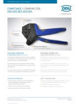
LED WORKLIGHT / ECLAIRAGE PAR LED / LED-BELEUCHTUNG / LUCES LED / ILLUMINAZIONE LED
2
ADAPTER / ADAPTATEUR / ADAPTER / ADAPTADOR / ADATTATORE AU130-C
3
U-HEAD / TETE U / U-KOPF / CABEZA U / TESTA A U
4
OPERATING BUTTON / GACHETTE DE COMMANDE / STARTKNOPF / BOTÓN DE ACCIONAMIENTO
/ PULSANTE DI AZIONAMENTO
5
PRESSURE RELEASE BUTTON / GACHETTE DE DECOMPRESSION / DRUCKABLASSKNOPF / BOTÓN
DESBLOQUEO PRESIÓN / PULSANTE DI SBLOCCO PRESSIONE
6
BATTERY / BATTERIE / AKKU / BATERÍA / BATTERIA
7
BATTERY RELEASE /
DEBLOCAGE BATTERIE / AKKU ENTRIEGELUNG / DESBLOQUEO BAT-
ERÍA /
SBLOCCO BATTERIA
8
TOUCH BUTTON FOR MENU SELECTION / TOUCHE POUR SELECTIONNER LE MENU / TOUCH-
TASTE FÜR AUSWAHLMENÜ / TECLA PARA SELECCIONAR EL MENÚ / TASTO A SFIORAMENTO
PER SELEZIONE MENU
9
DISPLAY / ECRAN / DISPLAYANZEIGE / PANTALLA / DISPLAY
10
RING FOR SHOULDER STRAP / ANNEAU POUR BANDOULIERE / TRAGERIEMENRING / ANILLO PARA
CORREA / ANELLO AGGANCIO TRACOLLA
FIG. / BILD 1
1
10
4
5
6
7
8
9
2
1
3

5
04
88
AU130-C
08
07
10
06
02
14
89
FIG. / BILD 4
ACCESSORIES
ACCESSOIRES
ZUBEHÖR
ACCESORIOS
ACCESSORI
~ 15 - 20 mm (0.6 - 0.8 in.)
FIG. / BILD 5
Hexagonal
dies
Sechskant
Presseinsätze
Matrices
hexagonales
Matrici
esagonali
Circular
dies
Rundpress-
einsätze
Matrices
semicircu-
lares
Matrici
semicircolari
Nest
and
Indent
dies
Matrize
und
Stempel
Matriz
y
punzón
Matrice
e
punzone
Adapter
AU130-C
Adattatore
AU130-C
Adaptador
AU130-C
AU130-C
Adaptor
Adaptateur
AU130-C
Matrice
et
Poinçon
Matrices
circulaires
Matrices
hexagonales

6
UP 130-25
UP 130-35
UP 130-50
UP 130-70
UP 130-95
UP 130-120
UP 130-150
UP 130-185
UP 130-240
UP130-300
10 - 16
25
35
50
70
95
120
150
185
240
300
AC 130-P
AU 130-150
AU 130-240
PS 130-35/E
MV 35 MVM 35 MUA 35
CONNECTORS - CONNECTEURS - VERBINDER - CONECTORES - CONNETTORI
CAA..-M MTMA... MTA... AA...-M
MTA..-C
Conductor section
Section conducteur
Leiter Querschnitt
Sección cable
Sezione cavo
( mm
2
)
Upper adaptor
Adaptateur superieur
Oberen Adapter
Adaptador superior
Adattatore superiore
Lower adaptor
Adaptateur inferieur
Unteren Adapter
Adaptador inferior
Adattatore inferiore
Pre-rounding die
Matr. de mise au rond
Runddrückeinsätze
Preredondeador
Prearrotondatore
Indentor
Poinçon
Stempel
Punzón
Punzone
Long - Longue - Lang - Larga -Lunga
Universal - Universelles
Universal - Universale
Universale
Containing die - Matrice coquille - Haltematrize -
Matriz de sujeción - Matrice di contenimento
Short - Courte -
Kurz - Corta - Corta
PS 130-95/E
MV 95 MVM 95 MVC 95 MUA 95
PS 130-150/E
MV 150 MVM 150 MVC 150 MUA 150
MUA 300-34
Aluminium
Aluminio
Alluminio
MV 240 MVM 240 MVC 240 MUA 240
*
PS 130-240/E
Outside diameter of connector = 34mm
Diametre exterieur connecteur = 34mm
Verbinder Aussendurchmesser = 34mm
Diametro externo conector = 34mm
Diametro esterno connettore = 34mm
GUIDE TO THE SELECTION OF ACCESSORIES GUIDE POUR LA SELECTION DES ACCESSOIRES ZUBEHÖR FÜR DIE
TIEFNUTKERBUNG GUIA PARA LA ELECCIÓN DE ACCESORIOS GUIDA PER LA SCELTA DEGLI ACCESSORI
*

7
(1)
Directive 2006/42/EC, annexe 1, point 1.7.4.2 letter u
L
pA
= weighted continuous acoustic pressure level equivalent.
L
pCPeak
= maximum value of the weighted acoustic displacement pressure at the work place.
L
WA
= acoustic power level emitted by the machine.
(2)
Directive 2006/42/EC, annexe 1, point 2.2.1.1
Weighted root mean square in frequency of the acceleration the upper limbs are exposed to for each biodynamic
reference axis. Tests carried out in compliance with the indications contained in EN ISO 5349-1/2 Standard, and under
operating conditions much more severe than those normally found.
1. GENERAL CHARACTERISTICS
ENGLISH
B1350-UC B1350-UCE B1350-UCT B1350-UCA
Application range suitable for installing electrical compression connectors
for conductors up to 400 mm
2
(800 MCM) and Aluminium
conductors up to 300 mm
2
(600 MCM)
Rated crimping force
kN (US sh. ton)
132 (14.84)
Minimum crimping force
kN (US sh. ton)
125,2 (14.07)
Minimum operating pressure
bar (psi) 692 (10037)
Dimensions (ref. to Fig. 6) mm (inches) 351x369x83 (13.8x14.5x3.3)
Weight with battery kg (lbs) 6,3 (13.8)
Motor V DC 18
Operating temperature °C (°F) -15 to +50 (+5 to +122)
Recommended oil ENI ARNICA ISO 32 or equivalents
Operating speed twin speed operation and automatic switching from
a rapid advancing speed of the ram to a slower, more
powerful crimping speed
Safety maximum pressure valve
Rechargeable battery V / Ah / Wh 18 / 5.2 / 93.6
Type CB1852L (Li-Ion)
Weight kg (lbs) 0,66 (1.45)
Battery charger
ASC30-36
Input
type
EU
27044000
UK
27045000
AUS/NZ
27047000
USA/CAN
27046000
V / Hz 220 - 240 / 50 - 60 115 / 60
W85
Acoustic noise
(1)
L
pA
dB (A)
73
L
pCPeak
dB (C) 94.5
L
WA
dB (A) 79
Vibration
(2)
m/s
2
0.575 max.

8
ENGLISH
WARNING
Do not use the tool for purposes other than those intended by Cembre.
The operator should concentrate on the work being performed and be careful to maintain
a balanced working position.
Before starting work on electrical equipment, please ensure that either there are no live
parts in the immediate working area or that precautions are taken for working near live
parts in accordance with EN50110-1.
Do not use this tool on or near energised conductors without proper personal protective
equipment. Failure to observe this warning could result in severe injury or death.
The tool is unsuitable for continuous use and should be allowed to cool down following
uninterrupted, successive crimping operations; for instance, having exhausted a fully
charged battery in one session, delay battery replacement for a few minutes.
Protect the tool from rain and moisture. Water will damage the tool and battery. Electro-
hydraulic tools should not be operated in pouring rain.
2. INSTRUCTIONS FOR USE
IMPORTANT: Never pressurise the tool without inserting the dies, this could cause damage
to the head and the ram.
The part reference includes the following (Ref. to Fig. 7 page 57):
Hydraulic crimping tool.
AU130-C upper adaptor.
Li-Ion rechargeable battery (2 pcs).
Battery charger (model depends on the tool version).
Shoulder strap.
Plastic carrying case.
USB cable (Ref. to § 8).
The tool is supplied with the AU130-C upper adaptor, which will accept semicircular slotted dies (com
mon to Cembre 130 kN tooling) suitable for:
Circular or hexagonal compression on Copper, Aldrey, Aluminium or ACSR conductors.
Indentation on Copper conductors.
With the upper adaptor AU130-150, AU130-240 and lower adaptor AC130-P, the tool can accept:
Pre-rounding dies UP130-... used for converting Aluminium sectoral conductor to a compact,
round section.
Containing dies MV, MVC, MVM, MUA series to crimp connectors on Aluminium cables using the
deep indent crimping system.

9
ENGLISH
2.1) Preparation
When introducing or changing dies, the battery
must rst be removed from the tool.
The tool can be easily carried using either the handle or the
shoulder strap attached to ring (10) (Ref. to Fig. 1).
Before starting any work, check the battery charge
(Ref. to § 2.8) and recharge if necessary, following the
instructions in the battery charger user manual.
To replace the battery, remove it by pressing the release
button (7), then insert the new battery, sliding it into the
guides until it locks.
The display shows the operational parameters of the tool;
to customise them proceed as described in § 2.7.
Depending on the compression to be performed, proceed as described in § 4 or 5.
2.2) Die advancement
Press operating button (4) to activate the motor-pump and advance the lower die.
To halt the advancement, release operating button (4) and the motor will cut out.
Make sure the dies are exactly positioned on the desired crimp point otherwise re-open dies
following instructions as per § 2.4 and reposition the connector.
2.3) Compression
By keeping operating button (4) pressed, the motor con-
tinues to operate: the ram will gradually move forward
until the two dies touch.
The motor will stop automatically when the set pressure
has been reached.
To perform proper compression, press and hold the
operating button (4) until the motor stops automati-
cally.
Battery
7
4

10
ENGLISH
NOTE: To display the momentary force or pressure during
the work cycle, select the appropriate display from the
menu (Ref. to § 7). When the operating button is released
before the motor stops automatically, the display will show
the peak force (Fp) or the peak pressure (Pp) reached at
that instant.
To complete the work, press the operating button again until the motor stops automatically; the dis-
play will show the maximum force or pressure reached followed by "OK" to con rm correct operation.
The display "ERROR", combined with a beep and the LEDs ashing, indi-
cates an incorrect crimping procedure caused by the work cycle being
interrupted before the control parameters (force/pressure) of the tool
are reached.
This error appears when the pressure release button has been operated and the tool has already
reached a pressure > 100 bar. In this case, repeat the compression by pressing and holding the
operating button until the motor stops automatically.
2.4) Release of dies
By operating the pressure release button (5), the ram will retract
and open the dies.
2.5) LED Worklights
Whilst the tool is in operation, the compression area is illuminated
by two high luminosity LED Worklights that switch o automatical-
ly at the end of the cycle.
The LED Worklights can be disabled by following the procedure described in § 7.2.
2.6) Head rotation
For ease of operation, the tool head can rotate through 180°, allowing the operator to work in the
most comfortable position.
Do not attempt to rotate the head when the hydraulic circuit is pressurised.
2.7) Capacitive touch button for menu selection
This button is located under the display and allows selection of various
screens (Ref. to § 7); it only works when the display is on.
Wearing gloves or using other objects may inhibit the operation of the
button, therefore use a bare nger to apply only a light touch.
Do not apply pressure to or stab at the touch button, a light touch using a bare nger is
su cient. The command pulse is sent when the nger releases the button.
ERROR
Ï
Ð
Fm = 125.2 kN
F
p = 102.3 kN
Pm = 692 bar
P
p = 565 bar
Fm = 125.2 kN
OK
Pm = 692 bar
OK
3 SEC.
5

11
ENGLISH
2.8) Battery status
The battery is equipped with LED indicators that indicate the
remaining battery life at any time by pressing the adjacent
button (P):
4 LEDs illuminated: fully charged
2 LEDs illuminated: 50 % capacity
1 LED flashing: minimum charge, replace the battery
With the battery inserted into the tool, the remaining bat-
tery life can also be checked on the display, via touch button
selection (Ref. to § 7).
The screen shown alongside indicates that the battery Voltage has
dropped below a minimum safety threshold; under these conditions the
tool will not start, and it is necessary to recharge or replace the battery.
The approximate time to fully recharge a battery is about 100 minutes.
After each working cycle, and after the extraction of the battery from the tool, an integrated
battery cut-o device will operate after 70 s approx.
Then the LED nearest to button (P) will ash 5 times each 14 s approx. The battery will be
reactivated when it is reintroduced into the tool and the operating button is pressed.
2.9) Using the battery charger
Carefully follow the instructions in the battery charger user manual.
3. MAINTENANCE
The tool is robust, completely sealed, and requires very little daily maintenance.
Compliance with the following points, should help to maintain its optimum performance:
3.1) Thorough cleaning
Dust, sand and dirt are a danger for any hydraulic device.
Every day, after use, the tool must be wiped with a clean cloth taking care to remove any residue,
especially close to pivots and moveable parts.
Do not use Hydrocarbons to clean the rubber parts.
3.2) Storage case (Ref. to Fig. 7)
When not in use, the tool should be stored and transported in the plastic case, to prevent damage.
The case, type VAL-P39, is suitable for storing the tool, the accessories and up to 8 die sets and pre-
prepared compression connectors.
The VAL-130 steel case: size 360x280x48 mm (14.17x11x1.89 in.), weight 3 kg (6.62 lbs), is available
for storage of the accessories for crimping aluminium connectors with deep indent crimping system.
BATTERY
Ï
Ð
max.
BATTERY BATTERY
Ï
Ð
min.
P

12
ENGLISH
4. CRIMPING OF CONNECTORS ON ALUMINIUM CABLES USING THE DEEP INDENT
CRIMPING SYSTEM (
Ref. to Figs. 2, 3)
4.1) Pre-rounding conductor (for sectoral cables) (Ref. to Fig. 3a)
From the table on page 6 select the proper AU130-150 or AU130-240 upper adaptor and UP...
pre-rounding die for the appropriate conductor size to be rounded.
Insert the upper adaptor into the head (see § 6.1).
Insert the lower adaptor AC130-P into the ram (see § 6.2).
Insert the lower part of the pre-rounding die (94) into the AC130-P adaptor by pulling the release
button (92).
Position the conductor into the upper part of the pre-rounding die (95) and locate the preround-
ing die in the adaptor AU130-150 or AU130-240.
Ensure that the pre-rounding die is correctly located in the adaptor with its upper slot in
line with the internal adaptor pins.
Operate the tool until the upper and lower part of the pre-rounding die are fully closed, then
release the hydraulic pressure (see § 2.4) and remove the compacted round conductor.
4.2) Connector crimping (Ref. to Fig. 3b)
From the table (Fig. 6, page 6) select AU130-... upper adapter, MV... containing die and PS.. inden-
tor recommended for the conductor size.
Insert the upper adaptor AU130-150 or AU130-240 into the head (see § 6.1).
Insert the indentor PS130.../E into the ram (14) (see § 6.2).
Insert conductor into the connector; locate the connector into the MV.. (96) containing die; locate
the containing die in the adaptor AU130-150 or AU130-240.
For every operation ensure the die is correctly located in the adaptor with its upper slots in
line with the internal adaptor pins.
Operate the tool (see § 2.2), commence indent crimping from the barrel end for both splices and
terminals, following the sequence shown below.
Each indenting operation is completed when indentor and die are fully closed, it is recommended
to continue pumping until the motor stops automatically (see § 2.3), then release the hydraulic
pressure by pressing the button (5).
Move the containing die and match another slot in line with the internal adaptor pins and then
proceed with another compression.
CRIMPING SEQUENCE
1 2
1 4 3 2
Indentor

13
ENGLISH
5. CRIMPING OF CONNECTORS USING THE CIRCULAR OR HEXAGONAL COMPRESSION
SYSTEM (
Ref. to Figs. 4, 5)
5.1) Connector crimping
Fit upper adaptor AU130-C into the head (see § 6.1).
Select the appropriate die set for the connector to be
crimped.
Insert die set into the head (see § 6.3).
Insert the conductor into the connector.
Position the connector between the dies and ensure the
correct location of the crimp.
To crimp connector continue as § 2.2.
NOTE: when more compression is
required, proceed according to the
sequence and direction indicated
in the gure, uniformly spacing the
compressions.
6. ACCESSORIES ASSEMBLY/REMOVING
6.1) Upper adaptors (Ref. to Figs. 3, 5)
Insert the adaptor in the guides on the U-fork (33) until securely located, with the grooves on the
adaptor corresponding to the locators (06) on the U-fork head (10).
Remove the adaptor by pushing it o the locators and sliding from the head.
6.2) Lower adaptor and Indentors (Ref. to Fig. 3)
To insert AC130-P lower adaptor or indentor PS.../E press release botton (04) and insert them
into the seat on the ram (14) until secured by the die retaining pin (02).
To ease this operation, operate the tool to advance the ram (14) 15-20 mm (0.6 - 0.8 in.).
To remove, press the release button (04).
6.3) Semicircular slotted dies (Ref. to Fig. 5)
Press release botton (08) and insert the upper die (88) into the AU130-C adaptor (09) until secured
by the die retaining pin (07).
To remove the upper die, press the release button (08).
Press release botton (04) and insert the lower die (89) into the seat on the ram (14) until secured
by the die retaining pin (02).
To ease this operation,.operate the tool to advance the ram (14) 15-20 mm (0.6 - 0.8 in.).
To remove the lower die, press the release button (04).
1
2
1
2
2
1
terminal
connector
conductor
conductor
Connector

14
ENGLISH
7. DISPLAY
The OLED display switches on automatically when the operating or pressure release buttons are
pressed, and o after 60 seconds of non-operation.
The display shows:
The main operational parameters of the tool processed by the circuit board, such as peak pres-
sure or force reached.
Information on the condition of the tool, such as the charge level, the battery temperature and
maintenance requirements.
Any operational or procedural ERRORS.
Use the touch button (8) to navigate through the menu screens to manage INFORMATION AND
SELECTION:
7.1) INFORMATION SCREENS: display a pre determined parameter which will then appear each
time the tool is started and during the entire work cycle.
B1350
13AB485
Fm = 125.2 kN
Fp = 94.5 kN
Fm = 14.07 ton
Fp = 10.61 ton
1000
-12000
3
BATTERY
Pm = 10037 psi
Pp = 7575 psi
Pm = 692 bar
Pp = 522.3 bar
Fm: Minimum set force, expressed in kN.
Fp: Peak force reached, expressed in kN,
(screen as factory setting).
Fm: Minimum set force, expressed in USA sh. tons.
Fp: Peak force reached, expressed in USA sh. tons.
Pm: Minimum set pressure, expressed in bar.
Pp: Peak pressure reached, expressed in bar.
Pm: Minimum set pressure, expressed in psi.
Pp: Peak pressure reached, expressed in in psi.
Battery charge level.
No. of cycles performed.
No. of cycles before scheduled recommended maintenance.
Cembre logo, tool model.
Tool serial no.

15
To make a selected screen operational and appear at each start-up of the
tool, operate the touch button for at least 3 seconds; a continuous beep
will con rm the setting.
The capacitive menu selection button may not work if touched using objects or when wear-
ing gloves, therefore always operate it using a bare nger.
7.2) SELECTION SCREENS: control parameters that cannot be set as automatic upon start-up
of the tool, can be changed by operating the touch button:
Enabling/disabling the LED Worklights (factory setting LED ON)
When the screen is displayed,
touch the button for at least
3 seconds to deactivate or
reactivate operation of the LED
Worklights during tool use; a
continuous beep will con rm
the setting.
Return to original factory settings / rmware version
When the "RESET" screen is displayed, return the tool to its factory setting by operating the touch
button for at least 3 seconds; a beep will con rm the setting.
The RESET screen also shows the rmware version of the circuit board.
7.3) WARNINGS: these appear during operation and notify the operator of the status of the tool:
LOW BATTERY: replace the battery.
NOTE: when the battery Vage falls below a minimum safety threshold, the tool
will not start; although it is still possible to end the work cycle in progress.
BATTERY TEMPERATURE HIGH: remove the battery and wait until it cools down.
NO. OF CYCLES TO MAINTENANCE REACHED:
the tool continues to work however, it is recommended that it is sent to
Cembre for a complete overhaul (see § 8).
NOTE: this message, together with a beep, will reappear when the tool has
been idle for 30 seconds.
LED
OFF
LED
ON
LED
OFF
3 SEC.
LED
ON
13001
3
BATTERY
Ï
Ð
Ï
Ð
BATTERY
Ï
Ð
RESET
SW:S1J41AH
3 SEC.
ENGLISH

16
ENGLISH
7.4) ERRORS: these appear during operation, combined with a beep and ashing LED Worklights,
to notify the operator of procedural or operational errors.
Message Error description Solution
ERROR
Ï
Ð
The pressure release button (5) was
pressed before the control parameters
were reached (Force/Pressure).
Repeat the work cycle and wait for the motor
to stop automatically.
Interruption of the signal from the NTC
temperature probe of the battery.
Replace the battery.
If the problem persists, please contact
Cembre.
001
Ï
Ð
Abnormal power consumption of the
motor for more than 3 seconds.
The tool stops.
Wait for the display to turn o (60 sec.) or
remove and re-insert the battery, then re-
start the tool.
If the error occurs frequently, contact Cem-
bre.
002
Ï
Ð
Output voltage of the pressure transmit-
ter is out of the pre-set range.
Repeat the work cycle; if the error occurs
frequently, contact Cembre.
003
Ï
Ð
Failure to reach the set pressure within
30 seconds of continuous operation of
the machine.
Repeat the work cycle; if the error occurs
frequently, contact Cembre.
004
Ï
Ð
Overcharging of the battery with protec-
tion tripping.
The tool stops.
Wait for the display to turn o (60 sec.) or
remove and re-insert the battery, then re-
start the tool.
If the error occurs frequently, contact Cem-
bre.
Errors are displayed for about 30 seconds before being reset, but will display repeatedly in
the event of permanent anomalies.
8. CONNECTION TO COMPUTER (Smartool thecnology)
The memory card integrated in the tool records operating data for transfer via the USB cable supplied.
To view and manage this data, go to www.cembre.com and register in the dedicated area, then
download the free Cembre software CEM_SWBT01.
Keeping the Firmware of the tool updated, via free of charge download from here, will optimise
the tool’s performance.
9. RETURN TO Cembre FOR OVERHAUL
In the case of a breakdown contact our Area Agent who will advise you on the problem and give
you the necessary instructions on how to dispatch the tool to our nearest service Centre; if possible,
attach a copy of the Test Certi cate supplied by Cembre together with the tool or ll in and attach
the form available in the “ASSISTANCE” section of the Cembre website.
NTC
FAULT

60
This manual is the property of Cembre: any reproduction is forbidden without written permission.
Ce manuel est la proprieté de Cembre: toute reproduction est interdite sauf autorisation écrite.
Diese Bedienungsanleitung ist Eigentum der Firma Cembre.
Ohne vorherige schriftliche Genehmigung darf die Bedienungsanleitung weder vollständig noch teilweise vervielfältigt werden.
Este manual es propiedad de Cembre. Toda reproducción está prohibida sin autorización escrita.
Questo manuale è di proprietà della Cembre: ogni riproduzione é vietata se non autorizzata per scritto.
cod. 6261380
60
www.cembre.com
Cembre Ltd.
Dunton Park
Kingsbury Road, Curdworth - Sutton Coldfield
West Midlands B76 9EB (UK)
Tel.: +44 01675 470440 - Fax: +44 01675 470220
E-mail: [email protected]
www.cembre.co.uk
Cembre S.a.r.l.
22 Avenue Ferdinand de Lesseps
91420 Morangis (France)
Tél.: +33 01 60 49 11 90 - Fax: +33 01 60 49 29 10
CS 92014 - 91423 Morangis Cédex
E-mail: [email protected]
www.cembre.fr
Cembre España S.L.U.
Calle Verano 6 y 8
28850 Torrejón de Ardoz - Madrid (España)
Teléfono: +34 91 4852580 -
Telefax: +34 91 4852581
E-mail: [email protected]
www.cembre.es
Cembre GmbH
Heidemannstraße 166
80939 München (Deutschland)
Telefon: +49 89 3580676
E-mail: [email protected]
www.cembre.de
Cembre Inc.
Raritan Center Business Park
181 Fieldcrest Avenue
Edison, New Jersey 08837 (USA)
Tel.: +1 732 225-7415 - Fax: +1 732 225-7414
E-mail: [email protected]
www.cembreinc.com
Cembre S.p.A.
Via Serenissima, 9
25135 Brescia (Italia)
Telefono: +39 030 36921
Telefax: +39 030 3365766
E-mail: [email protected]
www.cembre.com
IKUMA GmbH & Co. KG
Boschstraße 7
71384 Weinstadt (Deutschland)
Telefon: +49 7151 20536 - 60
Telefax: +49 7151 20536 - 80
E-mail: [email protected]
www.ikuma.de
/