
© Copyright 2012 ATEN
®
International Co., Ltd.
ATEN and the ATEN logo are trademarks of ATEN International Co., Ltd. All rights reserved.
All other trademarks are the property of their respective owners.
This product is RoHS compliant.
Part No. PAPE-1224-200G
Printing Date: 04/2012
PE1216/PE1324 Energy PDU User Guide
PE1216/PE1324 Unité d’alimentation Energy PDU Guide d’utilisation
PE1216/PE1324 Energy-PDU Benutzerhandbuch
PE1216/PE1324 PDU de administración de energía Manual del usuario
Requirements
EC1000 Energy Box to monitor energy consumption and environmental
conditions of your PE1216/PE1324.
Optional Accessories
1. EC1000 Energy Box
2. Cable Holder: Lock-U-Plug (0X12-0017-300G)
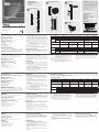
Hardware Review
A
Front View
1. Power Outlets
2. RJ-45 Port (Energy Sensor Port)
3. Circuit Breaker
4. Power Inlets (PE1216)
5. Power Cord (PE1324)
Hardware Installation
B
The PE1216/PE1324 can be installed in a 0U confi guration on the side of a
rack. To rack mount the device, use the rack mounting brackets that came
with your device. The brackets can be mounted either near the top and
bottom of the back panel, or the top and bottom ends of the device.
Voraussetzungen
Mit der EC1000 Energy-Box können Sie den Stromverbrauch und die
Umgebungsbedingungen Ihrer PE1216-/PE1324-Einheiten überwachen.
Optionales Zubehör
1. EC1000 Energy-Box
2. Kabelhalter: U-Klemmen (0X12-0017-300G)
Hardwareübersicht
A
Vorderseitige Ansicht
1. Strom-Abgänge
2. RJ-45-Port (Energiesensorports)
3. Leistungsschutzschalter
4. Strom-Zugänge (PE1216)
5. Netzkabel (PE1324)
Hardware installieren
B
Die PE1216/PE1324 kann in einer 0U-Konfi guration an einer Seite des
Racks montiert werden. Um das Gerät im Rack zu montieren, verwenden
Sie das mitgelieferte Rack-Montagekit. Die zugehörigen Schienen können
entweder oben oder unten an der Rückseite befestigt werden, oder oben
und unten am Gerätegehäuse.
Confi guration minimale
Vous aurez besoin d’une unité Energy Box EC1000 pour surveiller la
consommation d’énergie et les conditions environnementales de votre
PE1216/PE1324.
Accessoires en option
1. Unité Energy Box EC1000
2. Support de câble Lock-U-Plug (0X12-0017-300G)
Description du matériel
A
Vue avant
1. Prise de sortie
2. Port RJ-45 (Ports capteurs d’énergie)
3. Coupe-circuit
4. Prise d'entrée (PE1216)
5. Cordon d’alimentation (PE1324)
Requisitos
Un EC1000 Energy Box para monitorizar el consumo energético y las
condiciones ambientales de su PE1216/PE1324.
Accesorios opcionales
1. EC1000 Energy Box
2. Sujetadores de cables: Tipo U de insertar y fi jar (0X12-0017-300G)
Presentación del hardware
A
Vista frontal
1. Salidas de alimentación
2. Puerto RJ-45 (Puertos para sensores de energía)
3. Disyuntor
4. Entradas de alimentación (PE1216)
5. Cable de alimentacion (PE1324)
Requisiti
Energy Box EC1000 per monitorare i consumi energetici e le condizioni
ambientali della PE1216/PE1324.
Accessori opzionali
1. Energy Box EC1000
2. Portacavo: Chiusura di sicurezza a U (0X12-0017-300G)
Hardware
A
Vista anteriore
1. Prese per l’alimentazione
2. Porta RJ-45 (Porte sensori energetici)
3. Interruttore
4. Presa per l’alimentazione (PE1216)
5. Cavo di alimentazione (PE1324)
Installation
C
To set up an installation, refer to the installation diagrams (the numbers in
the diagram correspond to the numbered steps), and do the following:
1. For each device you want to connect, use its power cable to connect from
the device's AC socket to any available outlet on the PE1216/PE1324.
2. If using an EC1000 Energy Box (Optional), plug the cable that connects
the PE1216/PE1324 to the Energy Box into the PE1216/PE1324's RJ-45
port(s).
3. Connect the PE1216/PE1324's power cord to an AC power source.
Note: We strongly advise that you do not plug the PE1216/PE1324 into
a multi socket extension cord, since it may not receive enough
amperage to operate correctly.
Once you have fi nished these installation steps, you can turn on the Energy
PDU and the connected devices.
Note: We strongly recommend using cable ties and cable bars to safely and
securely route the cables attached to the back of the unit.
Securing the Cables
D
For added safety, use ATEN Lock-U-Plug cable holders to secure the cables
from your attached devices in place on the Energy PDU unit. Secure the
cable holders using the specially designed holes around the individual
power outlets
Installation
C
Zur Installation, siehe die Installationsdiagramme (die Nummern im
Diagramm entsprechen der Reihenfolge), und gehen Sie wie folgt vor:
1. Verbinden Sie jedes anzuschließende Gerät mit einer freien Steckdose
am PE1216/PE1324. Verwenden Sie dazu das jeweilige Netzkabel des
betreffenden Gerätes.
2. Wenn Sie eine EC1000 Energy-Box (optional) verwenden möchten,
verbinden Sie die PE1216/PE1324 und die Energy-Box mit einem
entsprechenden Kabel (die PE1216/PE1324 besitzt hierzu Ports mit RJ-
45-Buchsen).
3. Verbinden Sie das Netzkabel der PE1216/PE1324 mit dem
Wechselstromnetz.
Hinweis: Verbinden Sie die PE1216/PE1324 keinesfalls mit einer
Mehrfachsteckdose, da die verfügbare Stromstärke bei hoher
Last zu niedrig sein könnte.
Nachdem Sie die Installation beendet haben, können Sie die Energy-PDU
und die angeschlossenen Geräte einschalten.
Hinweis: Wir empfehlen, Kabelbinder und Kabelkanäle zu verwenden, um
die Sicherheit zu erhöhen, sowie die Kabel zusammengebunden
hinter dem Gerät entlangzuführen.
Installation du matériel
B
L’unité PE1216/PE1324 peut être installée dans un emplacement 0U sur
le côté du bâti. Pour installer l’unité sur un bâti, utilisez les supports de
montage sur bâti fournis avec l’appareil. Les supports peuvent être montés
soit à proximité du haut ou du bas du panneau arrière, soit sur le haut ou le
bas de l’appareil.
Installation
C
Pour effectuer l’installation, reportez-vous aux schémas d’installation (les
numéros des schémas correspondent aux étapes numérotées ci-dessous)
et procédez comme suit :
1. Pour chaque appareil que vous souhaitez connecter, utilisez son câble
d’alimentation pour relier la prise CA de l’appareil à n’importe quelle sortie
disponible de l’unité PE1216/PE1324.
2. Si vous utilisez une unité Energy Box EC1000 (en option), branchez le
câble destiné à connecter l'unité PE1216/PE1324 à l‘Energy Box dans
le(s) port(s) RJ-45 de l’unité PE1216/PE1324.
3. Connectez le cordon d’alimentation de l’unité PE1216/PE1324 à une
source d’alimentation électrique CA.
Instalar el hardware
B
La PE1216/PE1324 se puede instalar en una confi guración 0U en el lateral
de un rack. Para instalar el dispositivo en el rack, utilice las escuadras para
montaje en rack suministradas. Las escuadras pueden instalarse o bien
cerca de la parte superior o inferior en el panel posterior, o en los extremos
superior e inferior del dispositivo.
Instalación
C
Para instalar, véanse los diagramas de instalación (los números del
diagrama corresponden a los diferentes pasos a seguir) y proceda como se
indica a continuación:
1. Para cada dispositivo que desee conectar, enchufe su cable de
alimentación a una toma eléctrica de salida de la unidad PE1216/
PE1324.
2. Si va a emplear un EC1000 Energy Box (opcional), enchufe el cable de
interconexión de la PE1216/PE1324 al Energy Box en los puertos RJ-45
de la PE1216/PE1324.
3. Conecte el cable de alimentación de la PE1216/PE1324 a una toma
eléctrica.
Installazione dell'hardware
B
La PE1216/PE1324 può essere installata in una confi gurazione a 0U sul
lato del rack. Per montare sul rack il dispositivo, utilizzare le apposite staffe
in dotazione. Tali staffe possono essere montate sia sui lati superiore
e inferiore del pannello posteriore, sia sui lati superiore e inferiore del
dispositivo.
Installazione
C
Fare riferimento allo schema d’installazione (i numeri nella fi gura si
riferiscono ai punti numerati) e procedere come segue:
1. Per ogni dispositivo da collegare, utilizzare il relativo cavo d’alimentazione
per connettere la presa CA del dispositivo con una qualsiasi presa
disponibile della PE1216/1324.
2. Se si utilizza un’Energy Box EC1000 (opzionale), inserire il cavo che
collega la PE1216/PE1324 all'Energy Box nelle porte RJ-45 PE1216/
PE1324.
3. Collegare il cavo d’alimentazione della PE1216/PE1324 a una presa
d’alimentazione CA.
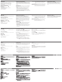
Specifi cations
Function PE1216A PE1216B PE1216G PE1324B PE1324G
Power
Outlets
Direct 16 x NEMA 5-15R 16 x IEC C13 16 x IEC C13 24 x IEC C13 24 x IEC C13
Connectors
Inlet 1 x IEC60320 C20 1 x IEC60320 C20 1 x IEC60320 C20 1 x NEMA L6-30P
1 x IEC 60309
32A
Energy Sensor
Port
1 x RJ-45 Female 2 x RJ-45 Female
Nominal Input Power
100-120V~, 50/60Hz,
20A(Max), 16A( UL de-rated)
100-240V~, 50/60Hz,
20A(Max), 16A( UL de-rated)
100-240V~,
50/60Hz,16A(Max)
100-240V~, 50/60Hz,
30A(Max), 24A( UL de-
rated)
100-240V~, 50/60Hz,
32A(Max)
Nominal Output Power
100-120V~, 50/60Hz
Per Outlet 15A (Max),
12A( UL de-rated)
Total : 20A(Max),
16A( UL de-rated)
100-240V~,50/60Hz
Per outlet 15A (Max),
12A( UL de-rated)
Total : 20A(Max),
16A( UL de-rated)
100-240V~,50/60Hz
Per Outlet 10A (Max)
Total : 16A(Max)
100-240V~,50/60Hz
Per bank 15A (Max),
12A ( UL de-rated )
Total : 30A(Max),
24A(UL de-rated)
100-240V~,50/60Hz
Per bank 16A (Max)
Total : 32A(Max)
Environment
Operating Temp. 0 – 50˚C
Storage Temp. -20 – 60˚C
Humidity 0 – 80% RH, Non-Condensing
Physical
Properties
Housing Metal
Weight 1.31 kg 1.31 kg 1.23 kg 3.47 kg 3.47 kg
Dimensions
( L x W x H )
73.00 x 4.40 x 4.40 cm 68.00 x 4.40 x 4.40 cm 134.00 x 4.40 x 4.40 cm
Kabel sicher verlegen
D
For added safety, use ATEN Lock-U-Plug cable holders to secure the cables from your attached devices in place on the Energy PDU unit. Secure the cable
holders using the specially designed holes around the individual power outlets
Technische Daten
Funktion PE1216A PE1216B PE1216G PE1324B PE1324G
Steckdosenausgänge Direkt 16 x NEMA 5-15R 16 x IEC C13 16 x IEC C13 24 x IEC C13 24 x IEC C13
Anschlüsse
Eingänge 1 x IEC60320 C20 1 x IEC60320 C20 1 x IEC60320 C20 1 x NEMA L6-30P 1 x IEC 60309 32A
Energiesensorport 1 x RJ-45 Buchse 2 x RJ-45 Buchsen
Nenn-Eingangsleistung
100-120 V~, 50/60 Hz, 20 A
(max.), 16 A (kein UL-Nennwert)
100-240V~, 50/60 Hz, 20 A
(max.), 16 A (kein UL-Nennwert)
100-240V~, 50/60 Hz,
16 A (max.)
100-240V~, 50/60 Hz,
30 A (max.),
24 A (kein UL-Nennwert)
100 - 240V~, 50/60 Hz;
32 A (max.)
Nenn-Ausgangsleistung
100-120 V~, 50/60 Hz
pro Steckdose 15 A (max.),
12 A (kein UL-Nennwert)
Gesamt: 20 A (max.),
16 A (kein UL-Nennwert)
100-240 V~, 50/60 Hz
pro Steckdose 15 A (max.),
12 A (kein UL-Nennwert)
Gesamt: 20 A (max.),
16 A (kein UL-Nennwert)
100-240V~, 50/60 Hz
pro Steckdose 10 A (max.)
Gesamt: 16 A (max.)
100 - 240V~, 50/60 Hz
pro Steckdosenleiste
15 A (max.),
12 A (kein UL-Nennwert)
Gesamt: 30 A (max.),
24 A (kein UL-Nennwert)
100- 240V~, 50/60 Hz
pro Steckdosenleiste
16 A (max.)
Gesamt: 32 A (max.)
Umgebung
Betriebstemperatur 0 – 50˚C
Lagertemperatur -20 – 60˚C
Feuchtigkeit 0 - 80% rel. Luftfeuchte, nicht kondensierend
Physische
Eigenschaften
Gehäuse Metall
Gewicht 1,31 kg 1,31 kg 1,23 kg 3,47 kg 3,47 kg
Abmessungen
(L x B x H)
73,00 x 4,40 x 4,40 cm
68,00 x 4,40 x 4,40
cm
134,00 x 4,40 x 4,40 cm
Remarque : Nous vous déconseillons fortement de brancher l’unité
PE1216/PE1324 sur une rallonge multiprise car elle ne
recevra peut-être pas un ampérage suffi sant pour pouvoir
fonctionner correctement.
Une fois les étapes d’installation terminées, vous pouvez allumer l’unité
d’alimentation Energy PDU et les périphériques connectés.
Remarque : Il est fortement recommandé d’utiliser des attaches de câble
et des barres guide-câble pour acheminer en toute sécurité les
câbles raccordés à l’arrière de l’unité.
Nota: Le advertimos que no debe conectar la PE1216/PE1324 a una
toma múltiple de un cable de extensión, dado que posiblemente no
reciba la corriente sufi ciente para funcionar sin problemas.
Cuando haya completado todos los pasos de la instalación, podrá encender
la PDU de administración de energía y los dispositivos conectados.
Nota: Le recomendamos que emplee bridas y canaletas para instalar los
cables de forma segura en la parte posterior de la unidad.
Nota: Non collegare il dispositivo PE1216/PE1324 ad una prolunga
con prese multiple, in quanto potrebbe ricevere un amperaggio
insuffi ciente per funzionare correttamente.
Una volta terminata l’installazione, è possibile accendere la PDU energetica
e i dispositivi collegati.
Nota: Si consiglia di utilizzare gli appositi stringi cavi e barrette per
arrotolare in maniera sicura ed effi cace i cavi collegati al retro del
dispositivo.
Fixation des câbles
D
For added safety, use ATEN Lock-U-Plug cable holders to secure the cables
from your attached devices in place on the Energy PDU unit. Secure the
cable holders using the specially designed holes around the individual
power outlets
Instalar los cables de forma segura
D
Para una mayor seguridad, fi je los cables de los dispositivos conectados
en la unidad PDU de administración de energía con los sujetadores para
cables de tipo U especiales de ATEN. Fije los sujetadores de cables en los
agujeros especialmente distribuidos alrededor de las tomas eléctricas.
Messa in sicurezza dei cavi
D
Per una maggiore sicurezza, utilizzare i passacavi ATEN con chiusura
di sicurezza a U per mettere in sicurezza i dispositivi collegati con l'unità
energetica PDU. Fissare i portacavi tramite i fori appositamente progettati
attorno alle singole prese di alimentazione.
B C
D
Package Contents
1 PE1216 / PE1324 Energy PDU
1 Power Cord (PE1216)
1 Mounting Kit
1 User Instructions
Hardware Installation Installation
Installation
Energy PDU
User Guide
PE1216/PE1324
TM
PE1216/PE1324 PDU energetica Guida dell’utente
FCC Information
This equipment has been tested and found to comply with the limits
for a Class A digital device, pursuant to Part 15 of the FCC Rules.
These limits are designed to provide reasonable protection against
harmful interference in a residential installation. This equipment
generates, uses and can radiate radio frequency energy, and if
not installed and used in accordance with the instruction manual,
may cause interference to radio communications. However, there
is no guarantee that interference will not occur in a particular
installation. If this equipment does cause harmful interference to
radio or television reception, which can be determined by turning
the equipment off and on, the user is encouraged to try to correct
the interference by one or more of the following measures:
• Reorient or relocate the receiving antenna;
• Increase the separation between the equipment and receiver;
• Connect the equipment into an outlet on a circuit different from
that which the receiver is connected;
• Consult the dealer/an experienced radio/television technician for
help.
Online Registration
International:
http://support.aten.com
North America:
http://www.aten-usa.com/product_registration
Technical Phone Support
International:
886-2-86926959
North America:
1-888-999-ATEN Ext: 4988
United Kingdom:
44-8-4481-58923
The following contains information that relates to China:
All information, documentation, and specifi cations contained
in this media are subject to change without prior notifi cation
by the manufacturer. Please visit our website to fi nd the
most up to date version.
PE1216
PE1324
1
1
2
1
2
3
5
2
4
3
2
1
www.aten.com
www.aten.com
www.aten.com
www.aten.com
www.aten.com
A
Hardware Review
Page is loading ...
-
 1
1
-
 2
2


ATEN PE1324 Quick start guide
- Type
- Quick start guide
Ask a question and I''ll find the answer in the document
Finding information in a document is now easier with AI
in other languages
- italiano: ATEN PE1324 Guida Rapida
- français: ATEN PE1324 Guide de démarrage rapide
- español: ATEN PE1324 Guía de inicio rápido
- Deutsch: ATEN PE1324 Schnellstartanleitung
- русский: ATEN PE1324 Инструкция по началу работы
- português: ATEN PE1324 Guia rápido
- 日本語: ATEN PE1324 クイックスタートガイド
Related papers
Other documents
-
CableWholesale 10W1-17206 Datasheet
-
WEG CLT32 Installation guide
-
-
Magtek ExpressCard 1000 Operating instructions
-
 Hach EC1000 User manual
-
-
 Altusen eco PDU PE1208 User manual
-
-
ATEN Technology PE8324 User manual
-

