Page is loading ...

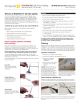
SAFETY INFORMATION
■
DANGER: Risk of eye damage. Do not stare directly at the LED chips
of this LED strip.
■
CAUTION: Do not power LED tape while coiled on reel.
■
IMPORTANT: Always observe polarity for 12-volt connections, positive
(+) to positive and negative (–) to negative.
■
IMPORTANT: Do not install Class 2 low voltage wiring in the same runs
as AC main power. If AC and low voltage wires cross, keep them at
90-degree angles. Use only insulated staples, plastic ties, or wire
support clips to secure cords and wires.
■
NOTICE: LED flexible tape lighting rating: 12VDC 2.5A.
■
Only use the 12-volt LED lighting power supply which has been
provided with this kit.
■
Do not bend, crush or pull the cable. Protect from sharp edges,
oil and heat.
■
For indoor/dry location use only.
■
Ensure the connectors are securely fastened before operating the tape.
■
Electrical waste should not be disposed of with household waste.
Please recycle where facilities exist.
Two-year limited warranty
WHAT IS COVERED
The manufacturer warrants this fixture to be free from defects in materials
and workmanship for a period of two (2) years from date of purchase.
This warranty applies only to the original consumer purchaser and only
to products used in normal use and service. If this product is found to be
defective, the manufacturer’s only obligation, and your exclusive remedy, is
the repair or replacement of the product at the manufacturer’s discretion,
provided that the product has not been damaged through misuse, abuse,
accident, modifications, alteration, neglect, or mishandling. This warranty
shall not apply to any product that is found to have been improperly
installed, set-up, or used in any way not in accordance with the instructions
supplied with the product. This warranty shall not apply to a failure of the
product as a result of an accident, misuse, abuse, negligence, alteration,
faulty installation, or any other failure not relating to faulty material or
workmanship. This warranty shall not apply to the finish on any portion of
the product, such as surface and/or weathering, as this is considered normal
wear and tear.
WHAT IS NOT COVERED
The manufacturer does not warrant and specifically disclaims any warranty,
whether expressed or implied, of fitness for a particular purpose, other than
the warranty contained herein. The manufacturer specifically disclaims any
liability and shall not be liable for any consequential or incidental loss or
damage, including but not limited to any labor/ expense costs involved in
the replacement or repair of said product.
Contact customer support at 410-354-6000, [email protected],
or visit armacostlighting.com/support.
Installation considerations
■
Where will you locate your power supply?
■
How will you run and conceal the wires to your LED tape lighting?
■
What is the best mounting position for the LED tape light to achieve
your desired effect?
■
See the section titled “Mounting options” for cabinet lighting
placement tips.
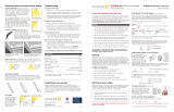
PACKAGE CONTENTS
Plug-in power supply
16 feet LED
tape light
(pre-assembled)
Wire Lead Connectors (optional use) Wire support clips
INSTALLATION
Cutting the tape light (optional)
■
To use the included connectors, cut the LED tape with scissors in the
center of a copper pad (position A) as shown, or attach the connector
to the copper pad found at the end of the tape.
■
The tape can also be cut at silver solder joints (position B), but this
cut point should be used for soldered connections only
Cut tape
at center of
copper pads
Okay to cut at silver
solder joints, but
do not use connector
■
Use a wire lead connector to make turns and go around corners. They
can also be spliced and extended for gaps of any size. 18-20 AWG
wire is recommended for custom lengths (not included).
+
–
Add wire to fit needs
■
IMPORTANT: Make sure to observe polarity when making connections,
positive to positive and negative to negative. Check to see that the
wire colors and the polarity markings printed on the tape line up.
Positive
Negative
■
NOTE: Be sure all 12-volt connections are secure and protected from
electrical shorting. Options include electrical tape, small wire nuts,
crimp connectors, etc.
1
AC Dimmable LED Tape Light Kit
Item 421502

2
How to use included connectors
■
The wire lead connectors are used to join two sections of LED tape.
■
Open the lid of the connector opposite the wire.
■
Peel about 1/4 inch of the paper from the LED strip adhesive backing
at the connection point.
■
Use a gentle side-to-side motion to slide the strip into the connector,
making sure the tape slides under the internal connector contact points.
■
Perform a power test to be sure the connection is secure. If the LEDs
fl icker or do not light, repeat the steps in this guide.
Insert tape into
channel under
contact tabs
Be sure tape
slides into
channel groove
Press down
lid until it
snaps closed
Soldering the LED tape (optional)
■
Soldering is another method for joining wires to the tape light and
joining sections of tape light directly together.
Wire Lead Connection Splice Connection
Preparing the assembly location
■
Power the LED tape lighting and temporarily hold or tape into
position with painter’s tape or masking tape – do not remove the
adhesive paper backing.
■
Adjust the lighting to various angles and positions to get the desired
level of illumination and lighting appearance. If the LEDs create
undesirable light spots on walls, or refl ections, reposition the tape light
strip farther away from surfaces or try a different mounting angle.
■
Once you have determined your fi nal mounting position, remove
any dirt and dust present where the tape will be applied. Mounting
surfaces should be clean, completely dry, and as dust-free as
possible. For best results, install when temperatures are above 60ºF
(15ºC). When installing on painted surfaces, paint should be fully
cured based on manufacturer’s cure time.
Installing the LED strip
■
Working from one end to the other, remove the paper backing
protecting the adhesive and fi rmly press the LED tape down with
your fi ngers or a clean cloth, taking care not to press on the
individual LEDs.
■
Support and secure the power cables leading to the tape light with
the included wire support clips.
■
NOTE: Although the LED tape can be installed in curved and irregular
spaces, avoid sharp bends or bending on the solder joints as you
could damage the LED tape light. If an LED is inadvertently damaged
and fails to light, the remaining LEDs will continue to operate.
Installing the power supply
■
IMPORTANT: Do not power the LED tape while on the reel, as the LEDs
will overheat.
■
Connect the AC power cord to a live outlet.
■
If connected to a switched outlet, be sure the power is switched ON
for proper remote operation.
Direct wiring the power supply
■
WARNING: Disconnect power by unplugging the power cord or turning
off the circuit breaker before removing the power supply end caps.
■
IMPORTANT: All wiring must be in accordance with national and local
electrical codes, low-voltage Class 2 circuit. If you are unclear as to
how to install and wire this product, consult a qualifi ed professional.
■
When the power supply
end caps are removed,
the input and output
cables can be removed by
loosening the screws on
the power supply cable
connector terminal block.
■
Removing the low-voltage
output cable from the
power supply will allow
cable runs through
cabinets and around any
obstacles as needed for a
more custom installation.
When reinstalling the cables to the power supply, be sure to follow
the polarity printed on the case (white wire to +, gray to –).
■
To direct wire, remove the AC input cable/plug and connect black live wire
from a branch circuit to the line side (L) of the built-in terminal block and
connect the white neutral wire to the neutral side of the terminal block
(N), as indicated on the case. This LED power supply uses Class II AC
inputs with a fully isolated case; ground wire should not be connected.
■
Before restoring power, make sure all connections are tight and the
endcaps are reinstalled securely.
■
The 12-volt power cable to the tape lighting can be shortened or
lengthened as needed. 18AWG is recommended when lengthening
this cable; keep wire runs as short as possible. Always use suitable
wire connectors to meet installation requirements.
■
Use the optional screw-tabs for mounting securely when needed,
for example, underneath a kitchen cabinet.
TYPICAL WIRING DIAGRAM WHEN USED WITH AN AC DIMMER
Green Wire
Ground
Black Wire
120-Volt AC
Live HOT
White Wire
120-Volt AC
Neutral
Dimming LED Driver
DC output
to LED lighting
IMPORTANT: Remove end caps
to access wiring block underneath.
FOLLOW POLARITY PRINTED
ON LED DRIVER CASE

Dimmer Compatibility
Armacost Dimming LED Drivers are compatible with both forward phase
(leading edge, triac, incandescent) and reverse phase (electronic low-
voltage, ELV, and trailing edge) AC dimmers, including higher end lighting
controls, such as Lutron GRAFIK Eye
®
systems. They are also compatible
with low-voltage PWM dimmers and RGB color controllers.
Although virtually all dimmers will work with Armacost Dimmable LED
Drivers, Armacost Lighting recommends dimmers that can be programmed
or have an adjustment dial to set the low end dimming range, such as
Lutron
®
C•L and Leviton IllumaTech
®
Universal Dimmers.
IMPORTANT: Armacost drivers do not need a minimum wattage load for
proper operation, but some AC dimmers may have this requirement. Check
the specifi cations of your dimmer to confi rm that your lighting exceeds
this value, or choose a dimmer with little or no load requirement.
MOUNTING OPTIONS
■
To surface mount the LED tape light under a set of cabinets in one
continuous run, you may need to drill a 1/2 in. hole through any
cabinet side lip that may be present. Install LED tape light through
the hole and surface mount as a continuous run.
■
For maximum light output and to focus light on the work surface,
mount the tape light 1-2 inches behind the front cabinet lip. This
mounting position works best with dull or matte fi nished countertops.
The LED tape has
a wide beam angle
Mount on inside of cabinet
lip to reduce refl ections
■
To eliminate bright spots from highly refl ective countertops, mount
the tape light on the inside back of the cabinet lip frame facing
towards your backsplash. Because of the wide beam angle of the tape
light, this mounting position will still provide ample lighting.
■
When mounting under a cabinet or a shelf with no lip to hide the LED
tape light strip, create a visual barrier using a piece of quarter round
molding or any angle trim to hide the LEDs.
Creating above cabinet uplighting
■
Most cabinet tops have uneven surfaces. To create indirect uplighting
over cabinets, simply mount the LED tape on any rigid strip (e.g.,
thin lattice or corner guard molding) and place on top of cabinets.
Angle the strip position to achieve the desired illumination.
■
For a seamless glow and to avoid bright light spots, move the LED
tape light strip further from adjacent walls.
Mount LEDs
farther from
the wall to avoid
bright spots
CEILING
CARE AND CLEANING
■
To clean the light, use a clean dry or slightly damp cloth.
■
Do not use cleaners with chemicals, solvents or harsh abrasives
as damage to the light strip may occur.
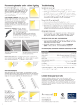
TROUBLESHOOTING
The LED strip will not light.
■
The power supply does not have power. Make sure the plug is fully inserted
into a live 120-volt outlet. Check connections and circuit breaker.
■
The power supply output cable is not properly secured. Make sure that the
DC output cable is wired securely to the output of the power supply.
■
The polarity is incorrect. Check that the orientation of the input and
output match the markings on the case.
Only part of the LED strip lights.
■
A connection point is faulty. Check for secure connections at the point
that is not lit. Confi rm that polarity is the same between the lit and
unlit segments.
The fuse blows or a circuit breaker trips when the light is turned on.
■
A wire is exposed. Discontinue use of the lamp. Unplug the unit from
the wall. Contact a qualifi ed electrician.
FCC STATEMENT
This device complies with part 15 of the FCC Rules. Operation is subject
to the following two conditions:
(1) This device may not cause harmful interference, and
(2) this device must accept any interference received, including
interference that may cause undesired operation.
CAUTION: Any changes or modifi cations not expressly approved by
the party responsible for compliance could void the user’s authority
to operate the equipment.
NOTE: This equipment has been tested and found to comply with the limits for a Class B
digital device, pursuant to part 15 of the FCC Rules. These limits are designed to provide
reasonable protection against harmful interference in a residential installation. This
equipment generates, uses and can radiate radio frequency energy and, if not installed
and used in accordance with the instructions, may cause harmful interference to radio
communications. However, there is no guarantee that interference will not occur in a
particular installation. If this equipment does cause harmful interference to radio or television
reception, which can be determined by turning the equipment off and on, the user is
encouraged to try to correct the interference by one or more of the following measures:
■
Reorient or relocate the receiving antenna.
■
Increase the separation between the equipment and receiver.
■
Connect the equipment into an outlet on a circuit different from that to which the
receiver is connected.
■
Consult the dealer or an experienced radio/TV technician for help.
CUSTOMER SUPPORT
Email: support@armacostlighting.com | Phone: 410-354-6000
Monday–Friday, 9 a.m.–5 p.m., EST
3
Baltimore, Maryland
armacostlighting.com
© 2019 Armacost Lighting. All rights reserved.
191101
/


