Armacost Lighting 611210 User guide

Type
User guide

This manual is also suitable for

30 RGB LEDs per meter (9 LEDs per foot)
Model # RF5050030-V2RGB
Ultra thin and flexible, RibbonFlex Pro Custom Color RGB LED
Tape Light is easy to install in straight, curved and irregular
spaces – offering virtually limitless design and installation
possibilities. With red, green and blue LED chipsets, RGB LED
lighting can produce a near endless array of colors, plus shades of
white, making it exceptionally versatile for creative accent lighting.
Please read completely before installing.
These guidelines will help you to understand how LED tape lighting can be
configured, cut to size, connected, and installed so you can successfully
design your own project-specific LED lighting layout.
Installing tape lighting is an easy DIY project, however, basic wiring skills
such as stripping, splicing, extending, and connecting wires are required.
This RGB LED tape lighting requires a 12V DC power supply and an RGB
color controller, available separately. An RGB LED Signal Repeater may be
required for longer length runs over 32 feet.
For help and advice with installations and to learn more about how to install
larger RGB application projects email [email protected].
IMPORTANT
When making any connections or cutting the RGB LED tape light,
make sure all power is disconnected. A short circuit will occur if any of
the energized White, Red, Green, or Blue wires come in contact with
each other which can permanently damage your RGB color controller.
Never connect tape light directly to 120-volt household power
Do not power LED tape while coiled on reel, as the LEDs will overheat.
The mounting surface will act as a heat sink to dissipate heat
Do not stare directly into the LED lights when illuminated
Never connect more than one power supply or color controller to a run
of LED lighting
Always use the +12V/G/R/B indicators printed on the tape light to
maintain polarity and correct color sequencing
Do not install this product in areas that are susceptible to direct
exposure to the elements
Use only insulated staples, plastic ties, or wire support clips to secure
cords and wires
Route and secure wires so they will not be pinched or damaged
Use properly certified CL2 or better cabling for wire runs inside walls
Do not install Class 2 low voltage wiring in the same runs as AC main
power. If AC and low voltage wires cross, keep them at 90-degree angles
All wiring must be in accordance with national and local electrical codes,
low voltage Class 2 circuit. If you are unclear as to how to install and wire
this product, contact a qualified professional.
Planning
RibbonFlex Pro RGB LED lighting is designed for indirect lighting
applications. The LEDs themselves are not intended to be seen directly
by the eye. Every installation is unique and the illumination effects are
personal preference. Installation location, wall colors, mounting angle, and
the light’s reflection off of walls, surfaces and objects will affect the final
lighting appearance. Subtle adjustments to the positioning and angle of
the LED tape can greatly impact the overall lighting effect.
Installation considerations
Where will you locate your power supply and RGB controller?
How will you switch your LED lighting on and off?
What is the best layout configuration for your installation?
What are the best ways to mount the tape lighting?
How will you cut, connect, and conceal the wires to your lighting?
RibbonFlex Pro
®
LED Accent Lighting
Custom Color RGB LED Tape Light
Choose an RGB color controller
A color controller is required for RibbonFlex Pro RGB LED lighting.
RGB color controllers blend the red, green, and blue light from the LED
chipsets allowing you to create custom colors and color-changing effects.
The color controller will also work as a dimmer and function as an on/off
switch. A wireless wall switch is also available. For current product
information on RGB color controllers, visit armacostlighting.com.
Choose a power supply
Power supplies come in various sizes with different wattages and are often
referred to as transformers, AC/DC adaptors, or LED drivers. RibbonFlex
Pro LED tape operates on low voltage and requires a power supply to
convert 120-volt household AC power to 12-volt DC power.
Never connect RibbonFlex LED Tape Lighting directly to 120-volt
household power
Only use RibbonFlex with Armacost Lighting approved LED drivers
and power supplies. Using other power supplies will void warranty
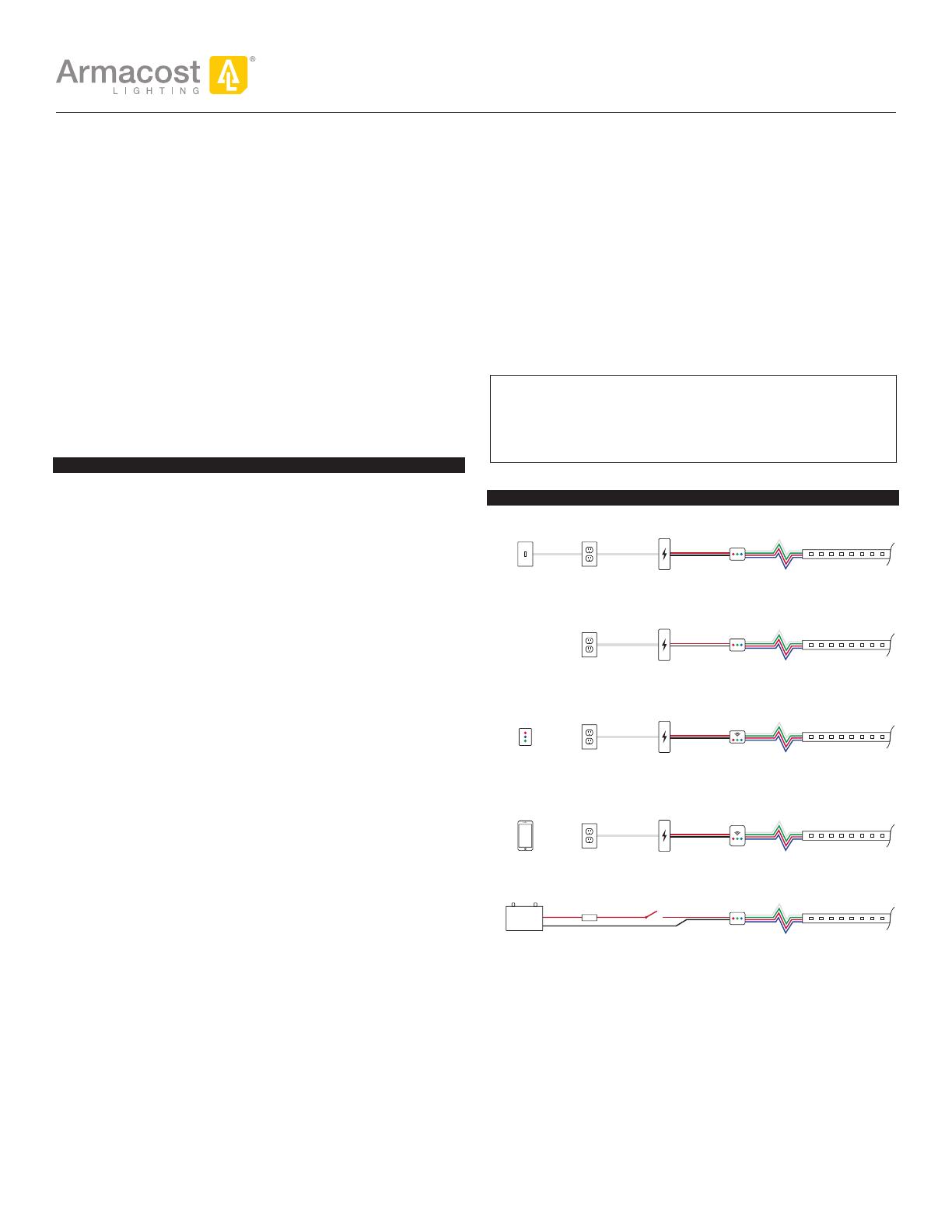
TYPICAL CONNECTION SCENARIOS
SWITCHED
AC OUTLET
12V DC
POWER SUPPLY
WALL
SWITCH
RGB
CONTROLLER
120V
AC OUTLET
12V DC
POWER SUPPLY
RGB
CONTROLLER
12V BATTERY
FUSE
PROTECTION
12V SWITCH
RGB
CONTROLLER
120V
AC OUTLET
12V DC
POWER SUPPLY
WIRELESS
TOUCHPAD FOR
RGB CONTROLLER
WIRELESS RGB
CONTROLLER
RECEIVER
120V
AC OUTLET
12V DC
POWER SUPPLY
SMARTPHONE
WITH WI-FI
MyLED APP
WI-FI LED
LIGHTING
CONTROLLER
Interior RV and boat applications can be powered directly by 12V battery
Power supply location and voltage drop
The shorter the wire is between the power supply, the RGB controller and
the tape lighting, the brighter and more consistent the color will be – do
not coil extra wire. If the RGB LEDs farthest from the power supply appear
dim or you see a color shift, it is due to voltage drop. Voltage drop only
becomes undesirable if you notice the brightness or color in one area of
your lighting is objectionably different than in another area. As a practical
approach, test your LED lighting prior to final installation. If voltage drop
appears to be an issue use heavier gauge wire, power tape light from both
ends, or use shorter length of lighting (see Typical Configurations).
To learn more, visit armacostlighting.com/installation for an easy-to-use
online voltage drop calculator.
1
Approximate watts used per meter at 100% bright white
RibbonFlex Pro Model RF5050030-V2RGB – 30 LEDs per meter
Meters 0.5 1 2 3 4 5 6 7 8 10
Feet 1.6 3.3 6.6 9.8 13 16.4 19.7 23 26.2 32.8
Watts used 4 8 15 21 25 29 32 35 38 40
Watts used is the power consumed by your LED lighting system,
not the watt rating of a power supply.
Always choose a power supply rated greater than your needs.
The watts used, as shown, are based on 100% full brightness white
light. Color changing or dimming of RGB LED lighting will use less
power and extend the life of LEDs.
Due to voltage drop, longer lengths of LED tape will use fewer watts
per meter than shorter lengths.
To accurately measure watts used by your LED lighting system, use a
multimeter. Watts is calculated by multiplying volts by amps used in
your LED system. To learn how to measure watts with a multimeter,
visit armacostlighting.com/multimeter.
Cutting, connecting and wiring
There are two methods for connecting power wires and splicing together two pieces
of LED tape lighting: soldering or using Armacost Lighting SureLock Connectors.
Soldering is a sure method for making strong, reliable electrical
connections. For tips on how to solder RibbonFlex Pro, visit
armacostlighting.com/installation.
Wire Lead Connection Splice Connection
Soldered connections are required for marine and RV applications due to
vehicle movement and vibrations.
Always connect RGB power wires to your tape lighting before removing the
3M tape backing and installing.
How to cut tape light
This RGB tape light model can be cut every 3 LEDs, or about every
4 in. Whether you are soldering wires or using connectors, cut the LED
tape with scissors directly in the center of the copper pad as shown in
position “A” below. You can also cut the tape at position “B,” however,
do not use connectors on soldered tape light joints, you can solder wires
at these joints.
Cut tape at center
of copper pads
B
Okay to cut at solder
joints, but do not
use connector
A
Always maintain same RGB
wire polarity when connecting.
Use the +12V/G/R/B
indicators printed on the
RGB tape light to maintain
the same polarity and
correct color sequencing.
+12V
G/R/B
Power supply size
Determining your wattage requirements
RGB LED tape lighting power requirements are stated in watts, and are based
on several factors, including your design confi guration. LED tape strips can be
installed in series (strips connected or wired end-to-end) or in parallel (multiple
legs of LED strips or series of strips wired directly to a single power supply).
TYPICAL CONFIGURATIONS
Straight Run
Only one end of the LED
strip is powered.
Multiple strips can be
connected in a series
for a continuous run. When set at 100% cool bright white, RGB LEDs
farther away from the color controller may color shift to a warmer white.
Center Feed / Loop Back
Either power two equal
legs of tape lighting
from the center or loop
back and power both
ends of the LED tape.
These confi gurations
will produce more
consistent brightness
and color over the
length of the strip.
A loop back is excellent for room perimeter tray ceiling or cove lighting.
Array
An array uses two or
more legs of various
lengths wired to an
RGB controller in a
parallel connection.
You will need to
calculate total wattage used in an array to guard against overloading
the power supply.
Choosing a higher wattage power supply does not necessarily mean you
can run longer lengths of LED lighting, however, it will allow for more
lighting legs in overall design. Exceeding the lengths in the following
chart will cause LEDs farthest from the power supply to color shift when
at 100% full bright white. Using a higher wattage power supply will not
reduce the effect of voltage drop.
Maximum recommended tape length
Model RF5050030-V2RGB, 30 RGB LEDs per meter
Straight run confi guration 10 meters (32.8 ft) – will use approximately 40 watts
Center feed confi guration 20 meters (65.6 ft) – will use approximately 80 watts
Array confi guration Varies based on layout and max wattage of power supply
For larger installations, install an Armacost Lighting RGB Signal Amplifi er
with an additional power supply, or use several wireless or WiFi RGB
controllers with separate power supplies in the same area, all paired
to the same operating channel and controlled by a remote touchpad or
smartphone. To learn more, visit armacostlighting.com/RGB.
Calculate the total wattage in your LED lighting system design
1. Use the following chart to determine the watts used in each leg
of lighting. A straight run is considered one leg. A center feed is
two equal lengths of lighting. An array can have many legs. As a
best practice use the next longer length on the chart to determine
approximate wattage per leg. Be sure to include only the lengths of
LED tape in your calculation. Do not include the connecting wires.
2. Add together the watts used for each leg of lighting to get total watts
used in your lighting layout. Note that watts shown in the chart
represent the approximate watts used when your color RGB LEDs are
set at full bright white. White light uses more energy than colors.
CONTROLLER
RGB
POWER
SUPPLY
POWER
SUPPLY
LEG 1 LEG 2
CONTROLLER
RGB
CONTROLLER
RGB
CONTROLLER
RGB
POWER
SUPPLY
POWER
SUPPLY
POWER
SUPPLY
LEG 3
LEG 1
LEG 2
CONTROLLER
RGB
2
Using SureLock
Connectors
SureLock Wire Lead Connectors
are used for going around
corners or, when cut in half,
to create two power leads or
jumper cables to bridge gaps
in order to get tape lighting to
other areas.
To increase the wire length
between two LED strips, simply
cut the connector wire in two, and splice in the length of wire needed.
18 gauge or heavier wire is generally recommended. Do not coil excess
wire; shorter lengths and thicker wire will mean less voltage drop and
higher brightness.
(
+12V
)
(G/R/B)
(
+12V
)
(G/R/B)
length to
t needs
Be sure all wire splice connections are secure and sealed. Options include
soldering, electrical tape, crimp connectors, terminal blocks, wire nuts, etc.
SureLock Splice Connectors
SureLock Splice Connectors are used to join two tape light strips, creating
a continuous run of lighting.
If the +12V/G/R/B marks do not line up,
ip the tape strip and use the opposite
end for proper +12V/G/R/B alignment.
(
+12V
) (
+12V
)
(G/R/B) (G/R/B)
Installing SureLock Connectors
SureLock Connectors – both the wire lead and splice models – connect to the
copper pads on cut sections of LED tape light. Connect to clean copper pads.
Do not use connectors on soldered joints.
Carefully peel back a small section of the 3M
®
adhesive tape paper
backing – remove only the paper, not the adhesive underneath.
With the connector in an upright position (logo facing up), carefully
insert the LED tape into the channel grooves, as shown below.
Use a gentle, side-to-side motion while inserting to make sure the
tape light is seated fully inside the connector.
Once the lighting is seated, push to close and securely lock the
pressure pad door. If needed, put the tape and connector upside
down on a hard surface and use a fl at head screwdriver to close and
lock the door in place.
Be sure
pressure pad
door snaps
securely into
connector
grooves
Once tape is fully inside
connector, close and lock
pressure pad door.
Use a fl at head screwdriver
to securely lock door if necessary.
Follow the same basic instructions when using SureLock Splice Connectors.
To view an online video tutorial, visit armacostlighting.com/surelock.
Connectors
Surface preparation and installation
Before removing the 3M paper backing, test the LED strip in the space you
intend to light. Once the paper backing is removed and the lighting is fully
installed, you cannot reposition or move the LED tape light to another location.
The tape may not stick securely.
Do not power LED tape while coiled on reel, as the LEDs will overheat.
It is normal for the tape to feel warm to the touch when holding it. Once
installed, the mounting surface will act as a heat sink to dissipate heat.
Power the LED tape light and temporarily hold or tape into position with
painter’s tape – do not remove the 3M paper backing. Do not stare directly
into the LEDs.
Try various angles and positions to get the desired level of illumination and
lighting appearance. If the LEDs create undesirable bright spots on walls
or refl ections, reposition the tape light strip farther away from surfaces or
try a different mounting angle.
See placement options for under cabinet lighting on page 4.
Going around corners
Although LED tape lighting is thin and fl exible, it is not designed to make
sideways or lateral bends and turns, which can damage the lighting. Use a
SureLock Connector to go around corners or create soft bends with a loop
that will make the tape lighting change direction sideways.
Using a SureLock Wire Lead
Connector to make a corner turn
Use loop bend technique for coves
and above cabinet installations
Mounting surfaces should be smooth, clean, completely dry, dust
free and above 60ºF (15 ºC) before installing/sticking the LED tape
strip in place. Thoroughly clean all mounting surfaces with isopropyl
alcohol. Do not use common rubbing alcohol and household cleaners,
which may leave behind residues.
For best adhesion, lightly sand the surface where you will mount
the tape lighting with fi ne grit sandpaper (150-300 grit). Sand in a
circular motion rather than straight-line motion.
When installing on painted surfaces, paint should be fully cured
based on manufacturer’s cure time.
Be careful not to peel off the 3M adhesive from LED strip; just remove
the tan paper backing.
3M sticky back tape requires pressure to activate the adhesive.
Working from one end to the other, fi rmly press the tape down with
your fi ngers, taking care not to press on the individual LEDs.
Support power wire leads, especially when mounting under cabinets
and shelves.
Armacost
Lighting Wire
Support Clip
3
Placement options for under cabinet lighting
For maximum light output, mount the LED tape
towards the front of the cabinet with LEDs facing
down. To focus light on the work surface and also
light your backsplash, position the tape light an
inch or two back from the front of the cabinet.
This mounting position works best with dull or
matte fi nished surfaces.
If your countertop is refl ective, install the LED tape
lighting on the inside back of the cabinet lip frame
with the LEDs facing towards your backsplash.
This method helps eliminate unwanted light
refl ections and bright spots refl ecting off your
countertop. Because of the wide beam angle of the
tape light, this mounting position will still provide
ample lighting.
Continuous run mounting of LED tape lighting is
achieved by drilling a 1/2 in.
hole through cabinet side frame
lips. When mounting on the
back side of the front frame lip, use a multi-tool
oscillating saw to make small vertical cuts in the
dividers to create slots that allow the tape lighting
to pass from one cabinet to another.
Tape light installed through
a drilled hole.
Tape light installed through a slot
sawed into cabinet divider.
Create a visual barrier when mounting under a cabinet or shelf with no
lip to conceal the LED tape light strip. Use a piece of angle trim, quarter
round molding, or any type of trim desired to hide the LEDs.
Above Cabinet Uplighting
Most cabinet tops have uneven surfaces. To create beautiful, indirect
uplighting over cabinets, simply mount RibbonFlex Pro on any rigid strip
(e.g., thin lattice or corner guard molding) and place on top of cabinets.
Angle the strip position to achieve the desired illumination.
Cove Lighting
Try different mounting
positions to get your
desired lighting effect.
For a seamless glow
with no bright light
spots, keep LED tape
light strip at least 1 in.
away from walls.
Mount LEDs
1 in.or greater
from wall to avoid
bright spots
CEILING
Troubleshooting
RGB tape light strip does not light
Make sure your LED power supply is turned on and receiving power.
Confi rm you have maintained correct polarity when connecting your
12V power supply to your RGB controller, and ensure that you have
maintained polarity and consistent wire color sequencing (+12V/G/R/B)
from the RGB controller to your LED tape light.
Check all tape light and RGB controller connections from the power
supply to the RGB LED tape light. Consider testing with a multimeter
to ensure light strip is receiving 12V power.
Only part of the LED tape light strip is lit
Check connections to the part of the strip that is not lit.
Confi rm that you have maintained correct polarity and wire color
sequencing to the unlit section.
If only 1 LED series is out, cut out and remove the damaged 3-LED group
and splice together LED tape strips or replace with new 3-LED section.
LED tape lights blink on, then go off
Your power supply is not adequate for the length of RGB LED tape light
you are powering. Install a higher wattage power supply or reduce watts
used by shortening the lengths of your LED tape lighting.
LEDs farthest from the power supply are noticeably dimmer or you see a color shift
This is the result of voltage drop. Decrease the length of the 12V power
feed wires or use thicker power feed wires between the 12V power
supply, the RGB controller, and the tape lighting.
Use shorter lengths of RGB LED tape lighting. Refer to Typical
confi gurations in these guidelines. Consider a different confi guration.
Visit armacostlighting.com/installation for additional installation tips and FAQs.
Limited three-year warranty
For terms and conditions, visit armacostlighting.com/warranty. Improper
installation, abuse, or failure to use this product for its intended purpose
will void warranty. This warranty only applies when all components,
including LED power supplies, have been provided by or approved for
use by Armacost Lighting. Substituting another manufacturer’s product
and/or components will void the warranty. The warranty does not cover
labor or any other costs or expense to remove or install any defective,
repaired or replaced products.
SPECIFICATIONS
Input Voltage ............................................................................ 12V DC
LED Count .......................................................................... 30 LEDs/m
LED Module ......................................................SMD 5050 tri-chip RGB
Beam Angle ..........................................................................120° wide
Tape Height/Width .................................................................2 x 10mm
Cuttable...................................................... Every 4 in. approx (100mm)
Listings ........................................................................ CE, RoHS, CSA
Country of Origin ......................................................................... China
140 Baltic Avenue
Baltimore, MD 21225
armacostlighting.com
© 2011-16 Armacost Lighting. All rights reserved. 160908
4
  • Page 1 1
  • Page 2 2
  • Page 3 3
  • Page 4 4

Armacost Lighting 611210 User guide

Type
User guide
This manual is also suitable for

Ask a question and I''ll find the answer in the document

Finding information in a document is now easier with AI