Page is loading ...

G
TH11 4
User Guide
Non-programmable
Thermostat
Description
Aube's TH114
non-programmable
thermostat
can be
used to
control
the ambient
air temperature or floor temperature.
You
can select
among the
following
temperature control modes:
2.1 Temperature
Display
(S1)
The
S1 switch is
used to select between
"C
(default)
and
"F.
2.2 Temperature
Control
Mode
(S2)
This
switch is
used
to
select the temperature
control
mode.
F. To
select the
F mode
(default)
AF: To
select the A or AF mode
O
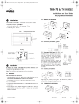
Installation
Upon
tests
ture.
Arrow
appears
when
the setpoint
is
displayed
A mode:
F mode:
AF
mode:
>
controls and displays
the ambient
air temperature
>
controls and
displays the floor
temperatur"
,ring
an external temperature
sensor
)
controls and
displays the ambient air temperature
>
maintains the floor
temperature within
desired
limits
using an external temperature
sensor
O
Refer to the installation instructions of the
power
base.
@ Insert
the tabs at the top of the control module in the
slots
at the
top of the
power
base.
O
Secure the control module using the
captive screw underneath
the base.
Control
module
Air vents
NOTE: Keep the thermosfaf's air
vents
clean and
unobstructed
at all
times.
-rL,
f-E
t-.-l
GFr[x-
I
1$t
I
Actual or setpoint
temperature
Unoccupied mode
indicator
Ground fault indicator
2
Temperature
adjustment
button
Backlight
button
On/Standby
switch
3 4
Heating
indicator
1
€=-
,:,
V
CiE
,0,
-.-l
!==
LL-
.LL-
I
The
thermostat displays the
percentage
use of heating required
to maintain the desired
temperature. For example,
1f
is displayed
when heating is
at
40
percent
Display
t
ft
lff
iltl
ftftl
% use of heating 1 Io 24% 25Io 49%
50 to 74% 75 to
99%
100%
'
GFI appears when
the
ground
fault
protection
has triggered.
3
Place
the thermostat in
Standby to cut
power
to the heater when it is
not in use
(e.g.
in
summer).
4
To reset
the
ground
fault
protection,
switch the thermostat to
Standby and back to On.
6| n^-i,^,tf
atiOn
9
r.rurrrrul
The
configuration
switches
are
located
at the
back of the control
module
(faceplate).
r\
!
AF
r
o
.;
Power-up
power-up,
the thermostat uncjergoes a series of
before disptaying the actuat
(measured)
temnera-
|
;f;
I
ll
$)
Error Messages
I L
l:l
I
rne
measured temperature
is
below the
thermostat's dis-
I
nrrt
I
play
range.
Heating is activated.
I Hl I
ffre measured temperature is above the thermostat's
dis-
| |
play
range.
Heating is
deactivated.
|
,!r
I
Verify
the thermostat
and
sensor connections.
rHr4
400- 1
'1
4-0 1 6-4 1t3t07

@
sacktisht
backlight
button
is
The display
illuminates for
5 seconds
when the
pressed.
When
either of
the
rv
buttons is
pressed,
the display
illuminates
for
10 seconds.
The
setpoint
temperature appears
for 5
seconds,
then
the actual
(measured)
temperature
is displayed.
Ternpeiafure Oisplai
CnO Setting
o
7.1Setpoint
Temperature
The
thermostat
normally displays
the
actual
(measured)temperature.
To view
the setpoint,
press
once on one clf the
rv
buttons.
The set-
point
is
displayed
for
5 seconds.
To change
the setpoint,
press
one of
the
rv
buttons until
the
desired
temperature
is
displayed.
To
scroll
faster,
press
and hold the button.
7.2
Floor Temperature Limits
(AF
mode only)
The
thermostat
generally
turns
heating
On or Off
to con-
trol the
ambient temperature.
However, if the floor tem-
perature
drops below the set minimum
floor temperature
limit or
rises
above
the
maximum limit,
the thermostat
will
turn
heating On or Off respectively, regardless of the
ambient
temperature, to
maintain the floor temperature
within the desired limits.
The
minimum
and
maximum floor temperature limits
are
factory-set at
10 "C
(50
'F)
and 28
"C (82
'F)
respectively
the
limits,
proceed
as
follows.
O Switch
the thermostat to
Standbv.
To modify
@ While
pressing
any button, switch the thermostat back to On to
access
the
floor
temperature limit settings.
O
Press the Backlight
button briefly
to
switch between
minimum
and
maximum floor
temperature
settings.
O Press the
rv
buttons to set the desired limit.
€) Press the Backlight button for
3 seconds
to
save
your
modifica-
tions.
After
the data are saved, the thermostat
displays the
actual ambient
temperature
or
"-
-".
Nofe. Your modifications
are also saved if no
button
is
pressed
for
60
seconds.
7.3
Unoccupied
Mode
Note: This feature is
available only if
the thermosfat
is
mounted
on a
power
base that has
the unoccupied
mode input
(ECONO).
The thermostat
can be connected
to any
other
remote
control
device
equipped
with
a dry contact. When
the contact closes, the
Unoccu-
pied
mode is activated
and the
Unoccupied mode icon
is displayed,
In
this
mode,
the thermostat lowers
its setpoint
by 3.5'C
(7'F)
and all
temperature adjustments are
blocked except for
temporary bypass.
Temporary Bypass
To temporarily bypass the
Unoccupied mode,
press
the
backlight but-
ton. During the bypass,
.the
Unoccupied mode
icon flashes.
The
bypass
is automatically
cancelled
after 2 hours
or
if the
backlight
but-
ton
is
pressed
again.
@
Power
Setpoi
V
Warranty
Technical
SpecilicationC
supply.
Refer to
the
power
base
installation
instructions.
nt range
-
F mode:
5
'C
to
40
'C
(40 "F
to 104 "F)
-
A/AF
mode:
5
"C
to
30
"C
(40
"F
to 86
"F)
Floor limit range
(AF
mode):
5
'C
to 40
'C
(40
'F
-
104
'F)
D
sp'av
ranse
:il;::J;9i13?;gJii;1l"Jii;lf
,
Resolution: t
0.5
"C
(1.0
"F)
Duty cycle: Refer to the
power
base installation
instructions.
Storage:
-20
'C
to 50'C
(-4'F
-
120
"F)
Aube warrants this
product,
excluding
battery, to
be free from
defects
in
the workmanship
or materials,
under normal
use and
service, for
a
period
of three
(3) years
from the
date of
purchase
by
the
consumer.
lf at
any
time during the warranty
period
the
product
is
determined
to be defective
or malfunctions, Aube
shall repair
or replace
it
(at
Aube's
option).
lf the
product
is
defective,
(i)
return it, with
a bill
of sale or other
dated
proof
of
purchase,
to
the
place
from which
you
purchased
it, or
(ii)
contact Aube. Aube
will make
the determination
whether
the
orod-
uct should be returned,
or whether
a
replacement
product
can
be
sent to
you.
This warranty
does not
cover removal
or reinstallation
costs. This
war-
ranty
shall not apply if it
is
shown by Aube
that the
defect
or malfunction
was caused by damage
which occurred
while
the
product
was in the
pos-
session of
a consumer.
Aube's
sole
responsibility
shall be to repair
or replace
the
product
within
the terms
stated above. AUBE
SHALL NOT BE
LIABLE FOR
ANY
LOSS
OR DAMAGE
OF ANY KIND,
INCLUDING
ANY INCIDENTAL
OR CON-
SEQUENTIAL
DAMAGES
RESULTING,
DIRECTLY
OR
INDIRECTLY,
FROM
ANY
BREACH
OF ANY WARRANTY,
EXPRESS
OR IMPLIED,
OR ANY
OTHER FAILURE
OF THIS
PRODUCT.
Some
provinces,
states
or regions
do not
allow the exclusion
or limitation
of incidental
or
conse-
quential
damages,
so
this
limitation
may
not
apply to
you.
THIS WARRANTY
IS
THE
ONLY
EXPRESS
WARRANTY
AUBE
MAKES
ON THIS PRODUCT
THE DURATION
OF ANY
IMPLIED
WAR-
RANTIES, INCLUDING
THE WARRANTIES
OF MERCHANTABILITY
AND FITNESS FOR
A PARTICULAR
PURPOSE,
IS HEREBY
LIMITED
TO
THE
THREE-YEAR
DURATION
OF THIS
WARRANTY.
Some
prov-
inces,
states
or regions
do not
allow
limitations
on
how long
an
impried
warranty
lasts, so the
above
limitation
may
not apply
to
you.
This warranty
gives
you
specific legal
rights,
and
you
may
have
other
rights which vary
from
province,
state
or region to
another.
f=! rt---r--
=A=
Gustomer
Assistance
For any
questions
regarding
product
installation
or
operation,
contact
us at:
705, Montrichard
Saint-Jean-su r-Richelieu,
Quebec
J2X 5K8
Canada
Tel.:
(450)
358-4600
Toll-free.'1
-800-831
-AUBE
Fax:
(450)
358-4650
E-mail :
aube. [email protected]
For more
information
on
our
products,
visit
us at:
www.aubetech.com
',-i,:i;
Tt1114
400-114-016-4
1t3t07
/