Page is loading ...

TH114 400-114-000-C 1/3/07 1/2
Aube's TH114 non-programmable thermostat can be used to control
the ambient air temperature or floor temperature. You can select
among the following temperature control modes:
1
The thermostat displays the percentage use of heating required to maintain the desired
temperature. For example, is displayed when heating is at 40 percent.
2
GFI appears when the ground fault protection has triggered.
3
Place the thermostat in Standby to cut power to the heater when it is not in use (e.g. in
summer).
4
To reset the ground fault protection, switch the thermostat to Standby and back to On.
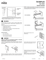
The configuration switches are located at the back of the control
module (faceplate).
2.1 Temperature Display (S1)
The S1 switch is used to select between °C (default) and °F.
2.2 Temperature Control Mode (S2)
This switch is used to select the temperature control mode.
n Refer to the installation instructions of the power base.
o Insert the tabs at the top of the control module in the slots at the
top of the power base.
p Secure the control module using the captive screw underneath
the base.
NOTE: Keep the thermostat's air vents clean and unobstructed at all
times.
Upon power-up, the thermostat undergoes a series of
tests before displaying the actual (measured) tempera-
ture.
The measured temperature is below the thermostat’s dis-
play range. Heating is activated.
The measured temperature is above the thermostat’s dis-
play range. Heating is deactivated.
Verify the thermostat and sensor connections.
n
Description
1.
A mode: controls and displays the ambient air temperature
F mode: controls and displays the floor temperature using
an external temperature sensor
AF mode: controls and displays the ambient air temperature
maintains the floor temperature within desired
limits using an external temperature sensor
Display
% use of heating 1 to 24% 25 to 49% 50 to 74% 75 to 99% 100%
o
Configuration
2.
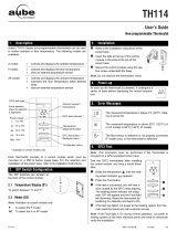
Backlight button
Temperature
adjustment button
On/Standby switch
3,
4
Heating
indicator
1
Actual or setpoint
temperature
Arrow appears
when the setpoint
is displayed
Ground fault indicator
2
Unoccupied mode
indicator
F: To select the F mode
AF: To select the A or AF mode (default)
p
Installation
3.
q
Power-up
4.
r
Error Messages
5.
Control module
Power base
Air vents
Air vents
TH114
User Guide
Non-programmable Thermostat
400-114-000-C (TH114 - mode A) ENG.fm Page 1 Thursday, March 1, 2007 11:53 AM

TH114 400-114-000-C 1/3/07 2/2
The display illuminates for 5 seconds when the backlight button is
pressed.
When either of the buttons is pressed, the display illuminates for
10 seconds. The setpoint temperature appears for 5 seconds, then
the actual (measured) temperature is displayed.
7.1 Setpoint Temperature
The thermostat normally displays the actual (measured) temperature.
To view the setpoint, press once on one of the buttons. The set-
point is displayed for 5 seconds.
To change the setpoint, press one of the buttons until the desired
temperature is displayed. To scroll faster, press and hold the button.
7.2 Floor Temperature Limits (AF mode only)
The thermostat generally turns heating On or Off to con-
trol the ambient temperature. However, if the floor tem-
perature drops below the set minimum floor temperature
limit or rises above the maximum limit, the thermostat will
turn heating On or Off respectively, regardless of the
ambient temperature, to maintain the floor temperature
within the desired limits.
The minimum and maximum floor temperature limits are
factory-set at 10 °C (50 °F) and 28 °C (82 °F) respectively. To modify
the limits, proceed as follows:
n Switch the thermostat to Standby.
o While pressing any button, switch the thermostat back to On to
access the floor temperature limit settings.
p Press the Backlight button briefly to switch between minimum
and maximum floor temperature settings.
q Press the buttons to set the desired limit.
r Press the Backlight button for 3 seconds to save your modifica-
tions. After the data are saved, the thermostat displays the
actual ambient temperature or “– –”.
Note: Your modifications are also saved if no button is pressed for 60
seconds.
7.3 Unoccupied Mode
Note: This feature is available only if the thermostat is mounted on a
power base that has the unoccupied mode input (ECONO).
The thermostat can be connected to any other remote control device
equipped with a dry contact. When the contact closes, the Unoccu-
pied mode is activated and the Unoccupied mode icon is displayed.
In this mode, the thermostat lowers its setpoint by 3.5°C (7°F) and all
temperature adjustments are blocked except for temporary bypass.
Temporary Bypass
To temporarily bypass the Unoccupied mode, press the backlight but-
ton. During the bypass, the Unoccupied mode icon flashes. The
bypass is automatically cancelled after 2 hours or if the backlight but-
ton is pressed again.
Power supply: Refer to the power base installation instructions.
Setpoint range - F mode: 5 °C to 40 °C (40 °F to 104 °F)
- A/AF mode: 5 °C to 30 °C (40 °F to 86 °F)
Floor limit range (AF mode): 5 °C to 40 °C (40 °F - 104 °F)
Display range - F mode: 0 °C to 60 °C (32 °F to 140 °F)
- AF mode: 0 °C to 50 °C (32 °F to 122 °F)
Resolution: ± 0.5 °C (1.0 °F)
Duty cycle: Refer to the power base installation instructions.
Storage: -20 °C to 50 °C (-4 °F - 120 °F)
Aube warrants this product, excluding battery, to be free from defects in
the workmanship or materials, under normal use and service, for a period
of three (3) years from the date of purchase by the consumer. If at any
time during the warranty period the product is determined to be defective
or malfunctions, Aube shall repair or replace it (at Aube's option).
If the product is defective,
(i) return it, with a bill of sale or other dated proof of purchase, to the
place from which you purchased it, or
(ii) contact Aube. Aube will make the determination whether the prod-
uct should be returned, or whether a replacement product can be
sent to you.
This warranty does not cover removal or reinstallation costs. This war-
ranty shall not apply if it is shown by Aube that the defect or malfunction
was caused by damage which occurred while the product was in the pos-
session of a consumer.
Aube's sole responsibility shall be to repair or replace the product within
the terms stated above. AUBE SHALL NOT BE LIABLE FOR ANY LOSS
OR DAMAGE OF ANY KIND, INCLUDING ANY INCIDENTAL OR CON-
SEQUENTIAL DAMAGES RESULTING, DIRECTLY OR INDIRECTLY,
FROM ANY BREACH OF ANY WARRANTY, EXPRESS OR IMPLIED,
OR ANY OTHER FAILURE OF THIS PRODUCT. Some provinces, states
or regions do not allow the exclusion or limitation of incidental or conse-
quential damages, so this limitation may not apply to you.
THIS WARRANTY IS THE ONLY EXPRESS WARRANTY AUBE
MAKES ON THIS PRODUCT. THE DURATION OF ANY IMPLIED WAR-
RANTIES, INCLUDING THE WARRANTIES OF MERCHANTABILITY
AND FITNESS FOR A PARTICULAR PURPOSE, IS HEREBY LIMITED
TO THE THREE-YEAR DURATION OF THIS WARRANTY. Some prov-
inces, states or regions do not allow limitations on how long an implied
warranty lasts, so the above limitation may not apply to you.
This warranty gives you specific legal rights, and you may have other
rights which vary from province, state or region to another.
For any questions regarding product installation or operation, contact
us at:
705, Montrichard
Saint-Jean-sur-Richelieu, Quebec
J2X 5K8
Canada
Tel.: (450) 358-4600
Toll-free: 1-800-831-AUBE
Fax: (450) 358-4650
E-mail: [email protected]m
For more information on our products, visit us at:
www.aubetech.com
s
Backlight
6.
t
Temperature Display and Setting
7.
u
Technical Specifications
8.
;
Warranty
9.
Customer Assistance
10.
400-114-000-C (TH114 - mode A) ENG.fm Page 2 Thursday, March 1, 2007 11:53 AM

PB112 400-112-006-C 26/2/07 1/1
n One (1) power base
o Two (2) screws
p Four (4) solderless connectors for copper wires
NOTE: Special CO/ALR solderless connectors must be used for connecting
aluminum conductors.
Option
q One (1) AC112-01 floor sensor (ordered separately; required for floor
heating applications only)
Turn off power to the heating system at the main electrical panel to
avoid electrical shock. The installation should be carried out by an elec-
trician.
NOTE: This power base must be used with thermostat operating on
15-minute cycles.
High voltage thermostats must be installed onto an electrical box.
The following guidelines are not necessary for floor heating applica-
tions:
For a new installation, choose a location about 1.5 m (5 ft) above the
floor and on an inside wall.
The thermostat must be installed on an inside wall facing the heating
system.
Avoid locations where there are air drafts (top of staircase, air outlet),
dead air spots (behind a door), direct sunlight or concealed chimneys or
stove pipes.
n Connect the power base wires to the power supply and load using sold-
erless connectors for copper wires (figure 1).
o For floor heating applications, insert the floor sensor wires through one
of the two holes below the terminals (figure 2) and connect the wires to
terminals 3 and 4 (no polarity).
NOTE: The wires must run alongside the terminals and not go over
them. The wire must not cross any heating wires nor be placed directly
on a heating wire or adjacent to it. For best performance, the sensor
probe should be centered between the wires in the mat.
WARNING: This power base does not have a built-in ground protection
device. Therefore, for floor heating applications, you must install a sepa-
rate ground protection device at the main electrical panel. Contact your
Aube authorized representative if you need a thermostat with built-in
ground protection device.
p If you wish to use a remote controller such as the CT240 or CT241,
insert the cable (use 18 to 22 gauge flexible wires) into one of the two
holes available below the terminal board and connect to terminals 1 and
2 of the base (figure 2).
q Push the excess length of the high-voltage wires back into the electrical
box.
r Secure the power base to the electrical box using the provided screws.
s If necessary, set the configuration switches on the control module (refer
to the control module user guide).
t Install the control module onto the base.
u Apply power to heating system.
Storage: -4°F to 120°F (-20°C to 50°C)
Remote controller input (ECONO): requires a dry contact
Size (H•W•D): 4.89 x 2.76 x 0.91 in. (124 x 70 x 23 mm)
Certifications:
n
Parts
1.
o
Guidelines
2.
p
Procedure
3.
q
Technical Specifications
4.
Model Supply Max. Load Power Wiring
120S 120 VAC, 50/60Hz 16.7 A 2000 W 4 wires / single pole
240S
240 VAC, 50/60Hz
208 VAC, 50/60Hz
16.7 A
4000 W
3475 W
4 wires / single pole
240D
240 VAC, 50/60Hz
208 VAC, 50/60Hz
15 A
3600 W
3120 W
4 wires / double pole
Power
Load
Figure 1
Figure 2
PB112
Installation Instructions
For models: 120S / 240S / 240D
400-112-006-C (PB112-120-240) ENG.fm Page 1 Monday, February 26, 2007 1:32 PM
/