Page is loading ...

3U Rackmount Server
ESC8000 G3
User Guide

ii
Copyright © 2016 ASUSTeK COMPUTER INC. All Rights Reserved.
No part of this manual, including the products and software described in it, may be reproduced, transmitted,
transcribed, stored in a retrieval system, or translated into any language in any form or by any means,
except documentation kept by the purchaser for backup purposes, without the express written permission
of ASUSTeK COMPUTER INC. (“ASUS”).
ASUS provides this manual “as is” without warranty of any kind, either express or implied, including but not
limited to the implied warranties or conditions of merchantability or tness for a particular purpose. In no
event shall ASUS, its directors, ofcers, employees, or agents be liable for any indirect, special, incidental,
or consequential damages (including damages for loss of prots, loss of business, loss of use or data,
interruption of business and the like), even if ASUS has been advised of the possibility of such damages
arising from any defect or error in this manual or product.
Specications and information contained in this manual are furnished for informational use only, and are
subject to change at any time without notice, and should not be construed as a commitment by ASUS.
ASUS assumes no responsibility or liability for any errors or inaccuracies that may appear in this manual,
including the products and software described in it.
Product warranty or service will not be extended if: (1) the product is repaired, modied or altered, unless
such repair, modication of alteration is authorized in writing by ASUS; or (2) the serial number of the
product is defaced or missing.
Products and corporate names appearing in this manual may or may not be registered trademarks or
copyrights of their respective companies, and are used only for identication or explanation and to the
owners’ benet, without intent to infringe.
E12284
Revised Edition V3
December 2016

iii
Contents
Notices ..................................................................................................................... viii
Canadian Department of Communications Statement .................................. viii
Australia statement notice ............................................................................. viii
Safety information ....................................................................................................... x
About this guide ......................................................................................................... xi
Chapter 1: Product Introduction
1.1 System package contents ......................................................................... 1-2
1.2 Serial number label .................................................................................... 1-3
1.3 System specifications ...............................................................................1-4
1.4 Front panel features ...................................................................................1-6
1.5 Rear panel features ....................................................................................1-6
1.6 Internal features .........................................................................................1-7
1.7 LED information .........................................................................................1-8
1.7.1 Front panel LEDs ........................................................................ 1-8
1.7.2 LAN (RJ-45) LEDs ...................................................................... 1-9
1.7.3 HDD status LEDs ...................................................................... 1-10
Chapter 2: Hardware Information
2.1 Chassis covers ...........................................................................................2-2
2.2 GPU fan air duct ......................................................................................... 2-3
2.3 Central Processing Unit (CPU) .................................................................2-5
2.3.1 Installing the CPU ....................................................................... 2-5
2.4 System memory .......................................................................................2-14
2.4.1 Overview ................................................................................... 2-14
2.4.2 Memory Congurations ............................................................. 2-15
2.5 Hard disk drives .......................................................................................2-18
2.5.1 Installing 2.5-inch SATA HDD/SAS HDD .................................. 2-18
2.5.2 Conguring an expansion card ................................................. 2-20
2.6 Cable connections ...................................................................................2-21
2.7 SATA/SAS backplane cabling .................................................................2-22
2.8 Installing M.2 card ....................................................................................2-23
2.9 Installing Accelerators .............................................................................2-24
2.10 Redundant power supply units ...............................................................2-29
2.11 Expansion cards ......................................................................................2-30

iv
Contents
Chapter 3: Installation options
3.1 Friction Rail Kit ...........................................................................................3-2
3.1.1 Attaching the rack rails ............................................................... 3-2
3.1.2 Mounting the server to the rack................................................... 3-4
Chapter 4: Motherboard Info
4.1 Z10PG-D24 Motherboard layout ...............................................................4-2
4.2 Jumpers ......................................................................................................4-4
4.3 Internal connectors ....................................................................................4-8
4.4 Onboard LEDs .......................................................................................... 4-18
Q-Code table .............................................................................................. 4-20
Chapter 5: BIOS setup
5.1 Managing and updating your BIOS ..........................................................5-2
5.1.1 ASUS CrashFree BIOS 3 utility................................................... 5-2
5.1.2 ASUS EZ Flash Utility ................................................................. 5-3
5.1.3 BUPDATER utility ....................................................................... 5-4
5.2 BIOS setup program ..................................................................................5-6
5.2.1 BIOS menu screen ...................................................................... 5-7
5.2.2 Menu bar ..................................................................................... 5-7
5.2.3 Menu items..................................................................................5-8
5.2.4 Submenu items ........................................................................... 5-8
5.2.5 Navigation keys ........................................................................... 5-8
5.2.6 General help................................................................................5-8
5.2.7 Conguration elds ..................................................................... 5-8
5.2.8 Pop-up window............................................................................5-8
5.2.9 Scroll bar ..................................................................................... 5-8
5.3 Main menu ..................................................................................................5-9
5.3.1 System Date [Day xx/xx/xxxx] ..................................................... 5-9
5.3.2 System Time [xx:xx:xx] ............................................................... 5-9

v
Contents
5.4 Advanced menu .......................................................................................5-10
5.4.1 ACPI Settings ............................................................................ 5-11
5.4.2 Smart Settings...........................................................................5-11
5.4.3 NCT6779D Super IO Conguration .......................................... 5-12
5.4.4 Onboard LAN I210 Conguration ............................................. 5-13
5.4.5 Serial Port Console Redirection ................................................ 5-14
5.4.6 APM .......................................................................................... 5-17
5.4.7 Advanced Power Management Conguration .......................... 5-18
5.4.8 PCI Subsystem Settings ........................................................... 5-19
5.4.9 Network Stack Conguration..................................................... 5-20
5.4.10 CSM Conguration .................................................................... 5-21
5.4.11 Trusted Computing.................................................................... 5-22
5.4.12 USB Conguration .................................................................... 5-23
5.4.13 iSCSI Conguration...................................................................5-24
5.5 IntelRCSetup menu .................................................................................. 5-25
5.5.1 Processor Conguration............................................................ 5-26
5.5.2 Advanced Power Management Conguration........................... 5-28
5.5.3 Common RefCode Conguration .............................................. 5-30
5.5.4 QPI Conguration......................................................................5-30
5.5.5 Memory Conguration ............................................................... 5-31
5.5.6 IIO Conguration ....................................................................... 5-34
5.5.7 PCH Conguration .................................................................... 5-35
5.5.8 Miscellaneous Conguration ..................................................... 5-37
5.5.9 Server ME Conguration ........................................................... 5-38
5.5.10 Runtime Error Logging Support ................................................ 5-38
5.6 Server Mgmt menu ...................................................................................5-39
5.7 Event Logs menu .....................................................................................5-43
5.8 Monitor menu ...........................................................................................5-44
5.9 Security menu ..........................................................................................5-45
5.10 Boot menu ................................................................................................5-48
5.11 Tool menu ................................................................................................. 5-49
5.12 Exit menu .................................................................................................. 5-50

vi
Contents
Chapter 6: RAID Configuration
6.1 Setting up RAID ..........................................................................................6-2
6.1.1 RAID denitions .......................................................................... 6-2
6.1.2 Installing hard disk drives ............................................................ 6-3
6.1.3 Setting the RAID item in BIOS .................................................... 6-3
6.1.4 RAID conguration utilities .......................................................... 6-3
6.2 LSI Software RAID Configuration Utility ................................................. 6-4
6.2.1 Creating a RAID set .................................................................... 6-5
6.2.2 Adding or viewing a RAID conguration.................................... 6-11
6.2.3 Initializing the virtual drives ....................................................... 6-12
6.2.4 Rebuilding failed drives ............................................................. 6-16
6.2.5 Checking the drives for data consistency.................................. 6-18
6.2.6 Deleting a RAID conguration ................................................... 6-21
6.2.7 Selecting the boot drive from a RAID set .................................. 6-22
6.2.8 Enabling WriteCache ................................................................ 6-23
6.3 Intel
®
Rapid Storage Technology enterprise
SCU/SATA Option ROM Utility ................................................................ 6-24
6.3.1 Creating a RAID set .................................................................. 6-26
6.3.2 Creating a Recovery set............................................................ 6-27
6.3.3 Deleting a RAID set...................................................................6-29
6.3.4 Resetting disks to Non-RAID .................................................... 6-30
6.3.5 Exiting the Intel
®
Rapid Storage Technology enterprise
SATA Option ROM utility........................................................... 6-31
6.3.6 Rebuilding the RAID..................................................................6-31
6.3.7 Setting the Boot array in the BIOS Setup Utility ........................ 6-33
6.4 Intel
®
Rapid Storage Technology enterprise (Windows) ......................6-34
6.4.1 Creating a RAID set .................................................................. 6-35
6.4.2 Changing a Volume Type..........................................................6-37
6.4.3 Deleting a volume ..................................................................... 6-38
6.4.4 Preferences ............................................................................... 6-39

vii
Contents
Chapter 7: Driver installation
7.1 RAID driver installation .............................................................................7-2
7.1.1 Creating a RAID driver disk......................................................... 7-2
7.1.2 Installing the RAID controller driver............................................. 7-3
7.2 Management applications and utilities installation ..............................7-13
7.3 Running the Support DVD ......................................................................7-13
7.4 Intel
®
chipset device software installation ............................................7-17
7.5 Installing the Intel
®
I210 Gigabit Adapters driver ..................................7-19
7.6 VGA driver installation ............................................................................7-22
7.7 Intel
®
Rapid Storage Technology enterprise 4.1 installation ............... 7-24
Appendix
ASUS contact information .......................................................................................... 2

viii
Notices
Federal Communications Commission Statement
This device complies with Part 15 of the FCC Rules. Operation is subject to the following two
conditions:
• This device may not cause harmful interference, and
• This device must accept any interference received including interference that may cause
undesired operation.
This equipment has been tested and found to comply with the limits for a Class A digital
device, pursuant to part 15 of the FCC Rules. These limits are designed to provide reasonable
protection against harmful interference when the equipment is operated in a commercial
environment. This equipment generates, uses, and can radiate radio frequency energy
and, if not installed and used in accordance with the instruction manual, may cause harmful
interference to radio communications. Operation of this equipment in a residential area is likely
to cause harmful interference in which case the user will be required to correct the interference
at his own expense.
Canadian Department of Communications Statement
This Class A digital apparatus complies with Canadian ICES-003.
Cet appareil numérique de la classe A est conforme à la norme NMB-003 du Canada.
The use of shielded cables for connection of the monitor to the graphics card is required
to assure compliance with FCC regulations. Changes or modications to this unit not
expressly approved by the party responsible for compliance could void the user’s authority
to operate this equipment.
Australia statement notice
From 1 January 2012 updated warranties apply to all ASUS products, consistent with the
Australian Consumer Law. For the latest product warranty details please visit https://www.
asus.com/support/. Our goods come with guarantees that cannot be excluded under the
Australian Consumer Law. You are entitled to a replacement or refund for a major failure and
compensation for any other reasonably foreseeable loss or damage. You are also entitled
to have the goods repaired or replaced if the goods fail to be of acceptable quality and the
failure does not amount to a major failure.
If you require assistance please call ASUS Customer Service 1300 2787 88 or visit us at
https://www.asus.com/support/
ix
REACH Information
Complying with the REACH (Registration, Evaluation, Authorization, and Restriction of
Chemicals) regulatory framework, we publish the chemical substances in our products at
ASUS REACH website at http://csr.asus.com/english/REACH.htm.
ASUS Recycling/Takeback Services
ASUS recycling and takeback programs come from our commitment to the highest standards
for protecting our environment. We believe in providing solutions for you to be able to
responsibly recycle our products, batteries, other components as well as the packaging
materials. Please go to http://csr.asus.com/english/Takeback.htm for detailed recycling
information in different regions.
DO NOT throw the motherboard in municipal waste. This product has been designed to enable
proper reuse of parts and recycling. This symbol of the crossed out wheeled bin indicates that the
product (electrical and electronic equipment) should not be placed in municipal waste. Check local
regulations for disposal of electronic products.
DO NOT throw the mercury-containing button cell battery in municipal waste. This symbol
of the crossed out wheeled bin indicates that the battery should not be placed in municipal
waste.
x
Safety information
Electrical Safety
• Before installing or removing signal cables, ensure that the power cables for the system
unit and all attached devices are unplugged.
• To prevent electrical shock hazard, disconnect the power cable from the electrical outlet
before relocating the system.
• When adding or removing any additional devices to or from the system, ensure that the
power cables for the devices are unplugged before the signal cables are connected. If
possible, disconnect all power cables from the existing system before you add a device.
• If the power supply is broken, do not try to x it by yourself. Contact a qualied service
technician or your dealer.
Operation Safety
• Any mechanical operation on this server must be conducted by certied or experienced
engineers.
• Before operating the server, carefully read all the manuals included with the server
package.
• Before using the server, ensure all cables are correctly connected and the power cables
are not damaged. If any damage is detected, contact your dealer as soon as possible.
• To avoid short circuits, keep paper clips, screws, and staples away from connectors,
slots, sockets and circuitry.
• Avoid dust, humidity, and temperature extremes. Place the server on a stable surface.
Lithium-Ion Battery Warning
CAUTION! Danger of explosion if battery is incorrectly replaced. Replace only with
the same or equivalent type recommended by the manufacturer. Dispose of used
batteries according to the manufacturer’s instructions.
CD-ROM Drive Safety Warning
CLASS 1 LASER PRODUCT
Heavy System
CAUTION! This server system is heavy. Ask for assistance when moving or carrying
the system.
This product is equipped with a three-wire power cable and plug for the user’s safety. Use
the power cable with a properly grounded electrical outlet to avoid electrical shock.

xi
About this guide
Audience
This user guide is intended for system integrators, and experienced users with at least basic
knowledge of conguring a server.
Contents
This guide contains the following parts:
1. Chapter 1: Product Introduction
This chapter describes the general features of the server, including sections on front
panel and rear panel specications.
2. Chapter 2: Hardware setup
This chapter lists the hardware setup procedures that you have to perform when
installing or removing system components.
3. Chapter 3: Installation options
This chapter describes how to install optional components into the barebone server.
4. Chapter 4: Motherboard information
This chapter gives information about the motherboard that comes with the server. This
chapter includes the motherboard layout, jumper settings, and connector locations.
5. Chapter 5: BIOS setup
This chapter tells how to change system settings through the BIOS Setup menus and
describes the BIOS parameters.
6. Chapter 6: RAID configuration
This chapter tells how to change system settings through the BIOS Setup menus.
Detailed descriptions of the BIOS parameters are also provided.
7 Chapter 7: Driver installation
This chapter provides instructions for installing the necessary drivers for different
system components.

xii
References
Refer to the following sources for additional information, and for product and software
updates.
1. ASUS Server Web-based Management (ASWM) user guide
This manual tells how to set up and use the proprietary ASUS server management
utility.
2. ASUS websites
The ASUS websites worldwide provide updated information for all ASUS hardware and
software products. Refer to the ASUS contact information.
Conventions
To ensure that you perform certain tasks properly, take note of the following symbols used
throughout this manual.
Typography
Bold text
Indicates a menu or an item to select.
Italics
Used to emphasize a word or a phrase.
<Key> Keys enclosed in the less-than and greater-than
sign means that you must press the enclosed key.
Example: <Enter> means that you must press
the Enter or Return key.
<Key1>+<Key2>+<Key3> If you must press two or more keys simultaneously,
the key names are linked with a plus sign (+).
Example: <Ctrl>+<Alt>+<Del>
Command
Means that you must type the command
exactly as shown, then supply the required
item or value enclosed in brackets.
Example: At the DOS prompt, type the
command line:
format A:/S
DANGER/WARNING: Information to prevent injury to yourself when
trying to complete a task.
CAUTION: Information to prevent damage to the components when
trying to complete a task.
NOTE: Tips and additional information to help you complete a task.
IMPORTANT: Instructions that you MUST follow to complete a task.

This chapter describes the general features of the chassis kit. It
includes sections on front panel and rear panel specications.
1
Product introduction
Chapter 1: Product Introduction
Chapter 1: Product Introduction
1-2
The system does not include a USB oppy drive. You may have to use a USB oppy drive
when creating a SATA RAID driver disk. Refer to Chapter 6 for details.
• ASUSSystemWeb-basedManagement
If any of the above items is damaged or missing, contact your retailer.
1.1 Systempackagecontents
Check your system package for the following items.
ESC8000G3
Chassis ASUS 3U Rackmount Chassis
Motherboard ASUS Z10PG-D24 Server Board
Accessory box
1 x MB Support DVD
1 x ASWM Enterprise DVD*
1 x ASMB8 SDVD
1 x Bag of Screws
3 x AC Power Cable
16 x GPU air ducts (8 for Intel Xeon PHi; 8 for Nvidia/AMD)
8 x Mylar for GPU air duct for AMD GPU
2 x CPU heatsink
1 x Rail Kit
16 x VGA power cables
8 x VGA power cables for Nvidia 300W and above GPU cards.
Optional Items
1 x PEM-FDR
1 x PEB-10G/57840-2S
1 x PEB-10G/57811-1S
1 x PIKE II 3108
1 x PIKE II 3008
ASUS ESC8000 G3
1-3
1
2
RESET
1.2 Serialnumberlabel
Before requesting support from the ASUS Technical Support team, you must take note of
the product’s serial number containing 12 characters such as xxS0xxxxxxxx. See the gure
below.
With the correct serial number of the product, ASUS Technical Support team members can
then offer a quicker and satisfying solution to your problems.
The serial number on ESC8000 G3 is printed on the Asset tag.
xxS0xxxxxxxx
ESC8000G3
Chapter 1: Product Introduction
1-4
1.3 Systemspecifications
The ASUS ESC8000 G3 servers features the ASUS Z10PG-D24 Series server board that
supports Intel
®
LGA 2011-3 Xeon
®
processor from the E5-2600 V3 product family.
(continued on the next page)
ModelName ESC8000G3
Processor/SystemBus
2 x Socket R3 (LGA 2011-3)
Intel
®
Xeon
®
processor E5-2600 v3 product family
QPI 6.4 / 8.0 / 9.6 GT/s
CoreLogic
Intel
®
C612 PCH
Memory
TotalSlots
24 (4-channel per CPU, 12 DIMMs per CPU)
Capacity
Maximum up to 1536 GB
MemoryType
DDR4 2133/1866/1600/1333* RDIMM/LR-DIMM/NVDIMM
MemorySize
4 GB, 8 GB, 16 GB, 32 GB (RDIMM)
32 GB, 64 GB (LRDIMM)
ExpansionSlots
TotalPCI/PCI-X/
PCI-ESlots
10
SlotType
Full-length/Full-height
8 x PCI-E 3.0 x16 (x16 Link) + 1 x PCI-E 3.0 x16 (x8 Link)
Half-lenth/Low-prole
1 x PCI-E 3.0 x8 (x8 Link)
Storage
SATAController
Intel
®
C612
- 6 x SATA 6Gb/s ports
- 1 x M.2 connector(support both PCI-E and SATA
interface.)
Intel
®
RSTe
supports software RAID 0, 1, 10, & 5 (for
Windows only)
LSI MegaRAID driver supports software RAID 0, 1, and 10
(Windows & Linux)
SASController
Optionalkits:*
ASUS PIKE II 3008 8-port SAS 12G RAID card
ASUS PIKE II 3108 8-port SAS 12G HW RAID card
*RequiresextraminiSASHDtominiSAScable
*Pleaserefertowww.asus.comforlatestmemoryAVLupdate
*3DPCsupportupto1600MT/sonly

ASUS ESC8000 G3
1-5
ModelName ESC8000G3
HDDBays
I=Internal
AorSwillbe
hot-swappable
6 x Hot-swap 2.5-inch HDD Bays
Networking
LAN
2 x Intel I210AT
1 x Management Port
Graphic
VGA
Aspeed AST2400 32 MB
FrontI/O
1 x External Serial Port
4 x Front USB ports (2 x USB 3.0, 2 x USB 2.0)
1 x VGA Port
RearI/O
3 x RJ-45 ports (One for ASMB8-iKVM)
OSSupport
Windows
®
Server 2012 R2
Windows
®
Server 2012
Windows
®
Server 2008 Enterprise R2 SP1
RedHat
®
Enterprise Linux
SuSE
®
Linux Enterprise Server
Ubuntu
CentOS
VMWare
Citrix XenServer
Management
Solution
OutofBand
Remote
Hardware
1 x ASMB8-iKVM for KVM-over-Internet (default)
Software
ASWM Enterprise
Dimension(HHxWWxDD)
759 mm x 447 mm x 130.6 mm (3U)
NetWeightKg(CPU,DRAM&
HDDnotincluded)
29.2 Kg
PowerSupply/PowerRating
100 - 127 / 200 - 240 Vac, 25.8 / 19A, 47-63 Hz Class I
Environment
Operating temperature: 10°C ~ 35°C
Non operating temperature: -40°C ~ 70°C
Non operating humidity: 20% ~ 90% (Non-condensing)
Systemspecifications
• Specications are subject to change without notice.
• Refer to www.asus.com for the latest OS AVL update.
Chapter 1: Product Introduction
1-6
1
2
RESET
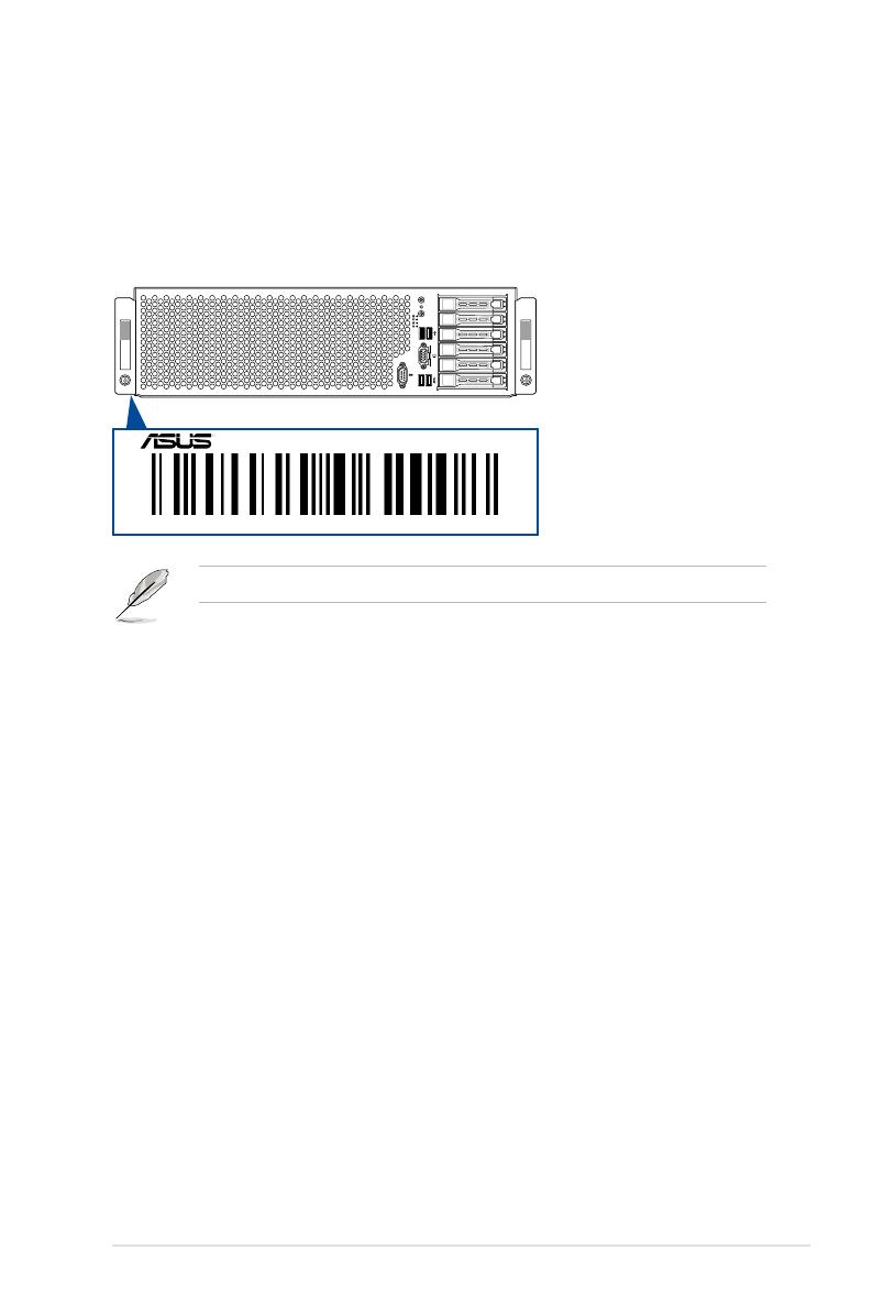
1.4 Frontpanelfeatures
The barebone server features a simple yet stylish front panel. The power and reset buttons,
LED indicators, and USB ports are located and easily accessible on the front panel.
USB2.0ports
Steelpullhandle
Steelpullhandle
Hot-swap2.5-inchHDDBays
Assettag(hidden)
MessageLED
LAN2LED
LAN1LED
HDDAccessLED
LocationbuttonwithLED
Resetbutton
PowerbuttonwithLED
USB3.0ports
VGAport
Serialport
The Dedicated Management LAN port is for the ASUS ASMB8-iKVM controller only.
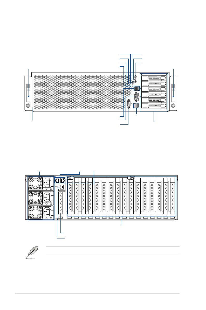
1.5 Rearpanelfeatures
The LAN ports and system power socket are located on the rear panel of the server.
Powercordconnectorand
Redundantpowersupply
LANports
LocateLED
DedicatedManagementLANport
Full-length/Full-heightexpansionslots
Half-length/Low-profileexpansionslot

ASUS ESC8000 G3
1-7
1.6 Internalfeatures
The barebone server includes the basic components as shown.
The barebone server does not include a oppy disk drive or an optical drive. Connect a
USB oppy disk drive to any of the USB ports on the front or rear panel if you need to use a
oppy disk.
WARNING
HAZARDOUS MOVING PARTS
KEEP FINGERS AND OTHER BODY PARTS AWAY
1. Redundant Power supply
(hidden)
2. ASUS Z10PG-D24 Server
Board
3. System fans
4. Hot-swap HDD tray (SAS
and SATA) (hidden)
5. Asset tag (hidden)
6. Half-length/Low-Prole
PCI-E Expansion slot
(hidden)
A protection lm is pre-attached to the front cover before shipping. Please remove the
protection lm before turning on the system for proper heat dissipation.

Chapter 1: Product Introduction
1-8
1.7 LEDinformation
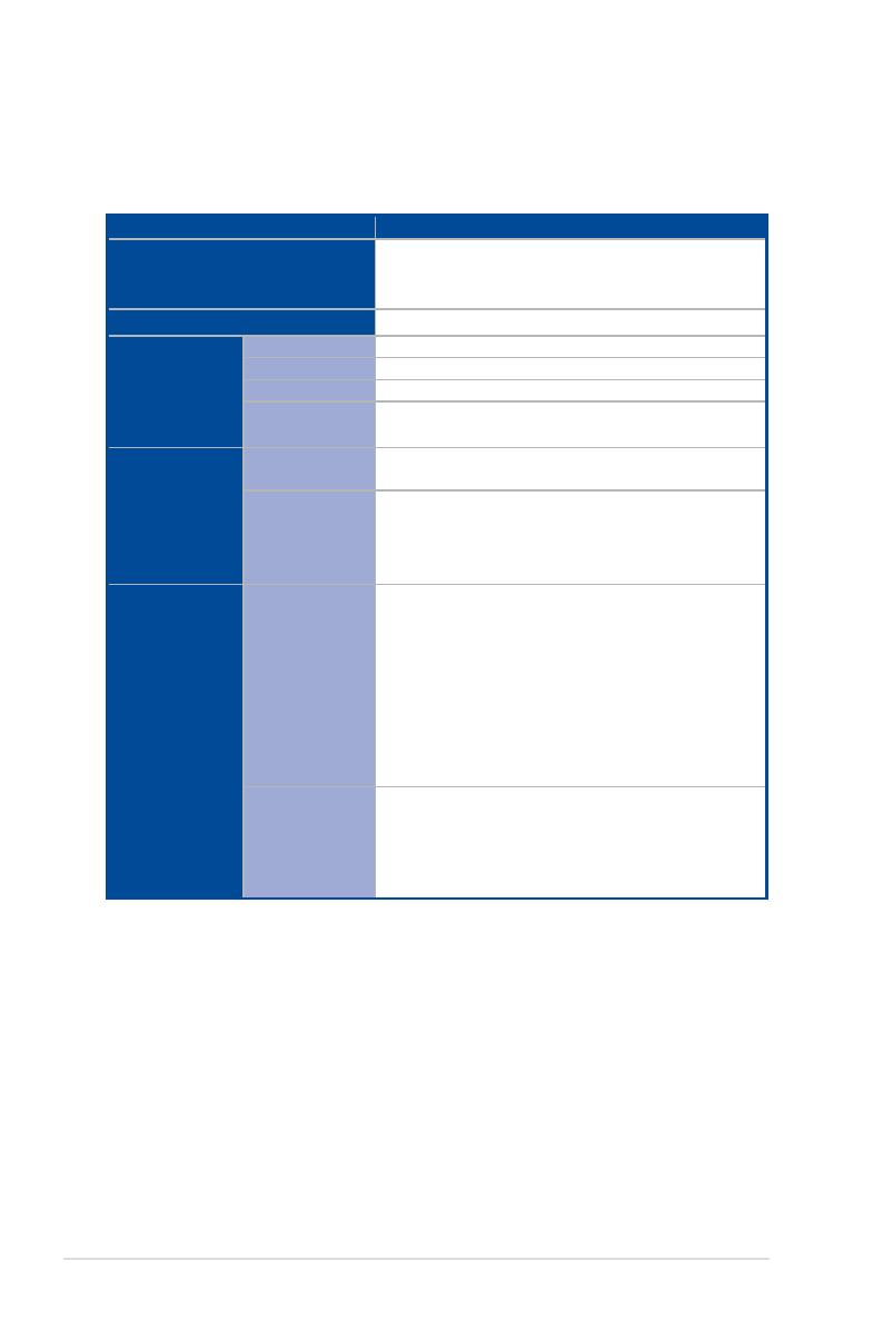
1.7.1 FrontpanelLEDs
LED Icon
Display
status
Description
Power button with LED
ON System power ON
HDD Access LED
OFF No activity
Blinking Read/write data into the HDD
Message LED
OFF System is normal; no incoming event
ON A hardware monitor event is indicated
Location button with
LED
OFF Normal status
ON
Location switch is pressed (Press the location switch
again to turn off)
LAN LEDs
OFF No LAN connection
Blinking LAN is transmitting or receiving data
ON LAN connection is present
1
2
RESET
ESC8000G3
RESET
MessageLED
LAN2LED
LAN1LED
HDDAccessLED
LocationbuttonwithLED
PowerbuttonwithLED
/