Page is loading ...

7/<3-+8+16/8-
%>+>/%><//>
"!9B
+<8/<
+B
AAA+7/<3-+8/+16/+---97
9./6(97:</==9<
9./6%'97:</==9<
9./6%97:</==9<
Manual Part No. 40984
Last Revision: 07/22/11
Subject to Change without Notification.
© 2011 American Eagle
Safety, Installation, Maintenance, and Operation
!) $F% '

6+==97:</==9<+8?+6$/@3=398=
+>/90$/@3=398
01/26/10
/=-<3:>39890$/@3=398
Updated SHD-60 Compressor Assembly to reflect
engineering changes.
%/->398$/@3=/.
Assembly
Drawings

i
&+,6/9098>/8>=
Introduction . . . . . . . . . . . . . . . . . . . . . . . . . . . . . . . . . . . . ii
%+0/>C
%:/-303-+>398=
General Specifications . . . . . . . . . . . . . . . . . . . . . . 2
Compressor System Description. . . . . . . . . . . . . . . 2
SHD-60 Drive System Description . . . . . . . . . . . . . . 2
!:/<+>398
General Operation Notes. . . . . . . . . . . . . . . . . . . . 3
SHD-60 Operation Notes . . . . . . . . . . . . . . . . . . . . . 3
+38>/8+8-/
8=>+66+>398
Compressor Installation. . . . . . . . . . . . . . . . . . . . . . 5
SHD-60 Installation . . . . . . . . . . . . . . . . . . . . . . . . . . 6
Pressure Setting Instructions . . . . . . . . . . . . . . . . . . 7
==/7,6C<+A381=
Crankcase Group (Tapered Shaft) . . . . . . . . . . . . 8
Crankcase Group (Straight Shaft) . . . . . . . . . . . . . 9
Cylinder Group. . . . . . . . . . . . . . . . . . . . . . . . . . . . 10
Head Group . . . . . . . . . . . . . . . . . . . . . . . . . . . . . . 11
Head Options . . . . . . . . . . . . . . . . . . . . . . . . . . . . . 12
Optional Head Unloader . . . . . . . . . . . . . . . . . . . 14
Flywheel Options . . . . . . . . . . . . . . . . . . . . . . . . . . 14
Clutch Options . . . . . . . . . . . . . . . . . . . . . . . . . . . . 15
SUH-60 Compressor Assembly . . . . . . . . . . . . . . . 16
SHD-60 Compressor Assembly . . . . . . . . . . . . . . . 17
C.<+?63-=6/-><3-+6
SHD-60 Control Kit . . . . . . . . . . . . . . . . . . . . . . . . . 18
Typical Hydraulic Circuit for Tandum (Two Part)
Pump with Multiple Components. . . . . . . . . . 19
Typical Hydraulic Circuit for Single Stage
Pump with Multiple Components. . . . . . . . . . 19
Typical Hydraulic Circuit for Compressor
with Auxiliary Cooler . . . . . . . . . . . . . . . . . . . . 20
$/:6+-/7/8>"+<>=
&<9?,6/=299>381
General Troubleshooting . . . . . . . . . . . . . . . . . . . 22
SHD-60 Troubleshooting. . . . . . . . . . . . . . . . . . . . . 23
Warranty Information . . . . . . . . . . . . . . . . . . . . . . . . . . . 26

ii Class 4 Compressor Owner’s Manual
American Eagle Compressors are designed
to provide safe and dependable service for
a variety of operations. With proper use and
maintenance, American Eagle Compressors
will operate at peak performance for many
years.
This manual contains information vital to the
safe use and efficient operation of this unit.
Following the information provided within this
manual can ensure the longevity of the
compressor. Carefully read and study the
operator’s manual before using the unit.
Failure to adhere to the instructions could
result in property damage or even serious
bodily injury to the operator or others close
to the compressor.
A copy of this manual is provided with every
compressor and shall remain with the
compressor at all times. Information
contained within this manual does not cover
all maintenance, operating, or repair
instructions pertinent to all possible situations.
This manual is not binding.
American Eagle reserves the right to
change, at any time, any or all of the items,
8><9.?->398
components, and parts deemed necessary
for product improvement or
commercial/production purposes. This right
is kept with no requirement or obligation for
immediate mandatory updating of this
manual.
This product manual is not intended as a
training manual for beginners or unskilled
operators. This manual offers guidelines for
correct and safe usage of the compressor,
maintenance, and troubleshooting. If more
information is required or technical
assistance is needed, please contact AE
Technical Support.
Some sections of this manual contain
information pertaining to all American Eagle
manufactured compressors and may or may
not apply to your specific model.
If this manual becomes damaged,
misplaced, or unreadable at any point, or if
you feel that any part of this manual is
unclear or incorrect, please contact AE
Technical Support at 800-321-3741 or email
&/-283-+6#?/=>398=+8.809<7+>398 [email protected]
!<./<"+<>= [email protected]
)+<<+8>C809<7+>398 [email protected]
9<&/-283-+6#?/=>398=809<7+>398"+<>=9<)+<<+8>C+66&966<//+>
Hours: Monday - Friday, 8:00 a.m. - 5:00 p.m. CST
Or email at the following addresses:

Safety 1
%+0/>C
This manual contains vital information for the safe use and efficient
operation of this unit. Carefully read the operators manual before starting
the unit. Failure to adhere to the instructions could result in serious bodily
injury or property damage.
Every American Eagle Compressor will
provide safe and dependable service if
operated according to instructions. Read
and understand the safety precautions
given in this manual and on the decals
attached to the shields. Failure to do so can
result in personal injury or equipment
damage.
Operators and maintenance personnel must
always comply with the safety precautions.
These precautions are given here for your
safety. Review them carefully before
operating the compressor and before
performing maintenance or repairs.
Supervising personnel should develop
additional precautions relating to the
specific work area and local safety
regulations.
"</-+?>398=
Always wear safety equipment such as
goggles, ear plugs and head protection at
all times when operating the compressor.
Do not inspect or clean the compressor
while the hydraulic power source is
connected. Accidental engagement of the
tool can cause serious injury.
Before performing any maintenance on the
compressor, place a warning tag on the
hydraulic power source or disconnect the
hoses from the compressor motor to prevent
accidental startup of the compressor.
Always connect hoses to the compressor
before energizing the hydraulic power
source. Be sure all hose connections are
tight, both air and hydraulic.
Establish a training program for all operators
to ensure safe operation.
Do not operate the compressor unless
thoroughly trained or under the supervision
of an instructor.
Do not operate the compressor if it is
damaged, improperly adjusted or not
completely or properly assembled.
Never operate the compressor with any of
the guards removed.
Do not attempt to adjust or disable the
compressors air pressure relief valve. This
valve limits the air pressure to 150 PSI.
The surface of the air compressor and the
plumbing between the compressor and the
cooler may reach temperatures above 150
degrees. Touching these surfaces during
operation can cause burns.
The air taken in by the air compressor must
be free of flammable fumes and vapors.
Compressor speed should not exceed 1300
RPM.
Use and operate this air compressor only in
full compliance with all pertinent O.S.H.A.
requirements and all Federal, State and
Local codes or requirements.

2 Class 4 Compressor Owner’s Manual
%:/-303-+>398=
D9./6 (
D)/312> 6,=%6,=
D/63@/<C "%
D+B37?7)9<5381"</==?</ "%
D37/8=398=% EBE)BE
D6/-><3-+6 (
D!36+:+-3>C #?+<>
DC638./<= 9?<C638./<%3816/%>+1/
D+B37?797:</==9<%://. $"
D"C.<+?63-%C=>/7 D"%%C=>/7"</==?</
D"%"</==?</$/63/0%/>>381 D(%96/893.98><96(+6@/
D66%>//6"6?7,381)3>>381= D%;8&'996/<
D(96>996/<+8 D6?738?7+83096.
D3</-><3@/9?:6381 D3<"</==?</98><96(+6@/
%<3@/%C=>/7/=-<3:>398
D+=><98<+85-+=/+=>381 D/+@C?->36/<98<+85=2+0>
D+=>6?738?7C638./</+. D3-<9298/.988/->381$9.=
D312&/7:/<+>?</"</-3=398"3=>98= D&+:/</.$966/</+<381=
D%>+386/==%>//6$//.(+6@/= D"</==?</?,<3-+>/.%C=>/7
D/+@C?>C9?<8+6?=2381= D!36"</==?</+?1/
D"?6=+>398+83096.
97:</==9<%C=>/7/=-<3:>398
/8/<+6%:/-303-+>398=

Operation 3
!:/<+>398
/8/<+6!:/<+>398 9>/=
/09</%>+<>':
Check the oil level in the compressor with the dipstick on the unit. If oil is needed, use
American Eagle synthetic compressor oil (P/N C0087) or an equivalent synthetic oil. 9>/
&2/</7+C,/9366/0>38>2/-<+85-+=/0<97>2/0+->9<C,/8-2>/=>!@/<03663817+C-+?=/
>2/-97:</==9<>9,+-5,69A9366A+C=-2/-5>2/9366/@/6+8.0366>9>2/./=318+>/.
7+<538198>2/.3:=>3-5,/09</:?>>381>2/?83>38>9=/<@3-/
Check the air intake filters on each head to make certain that they are clean and
unobstructed. Dirty air filters are a possible cause of reduced air output.
Each compressor is bench tested under load at the factory to ensure proper break-in and
operation. While it is not necessary to follow any break-in procedure, the following checks
should be made before putting the unit into service and periodically during use.
If adjustment is necessary for cable operated speed controls, loosen the jam nut on the
cable end, make the adjustment and retighten the jam nut.
For electronic operated speed controls, adjust speed adjustment screw as needed to set
RPM.
For setting engine RPM through the chassis ECM, contact local chassis dealer.
When the air pressure falls below 120 PSI, the 12 volt electric solenoid opens allowing
hydraulic oil to flow to the hydraulic drive motor then back to the manifold and through
the oil cooler assembly. Once the air pressure reaches 150 PSI the solenoid closes
shutting off the oil flow to the motor and diverts the oil to the oil cooler.
With the compressor engaged, the main cooling system, which consists of an oil cooler,
electric fan motor and fan continually runs drawing ambient air through the cooler fins
and across the fan assembly discharging heated air past the compressor and out the
cover assembly.
%!:/<+>398 9>/=
To use the compressor, start the engine and engage the hydraulic system with the
compressor toggle switch. Through the hydraulic valve manifold, the system will now
function automatically. Once engaged, adjust the engine speed control to ensure that the
compressor speed does not exceed 1300 RPM under load.

4 Class 4 Compressor Owner’s Manual
+38>/8+8-/
The following table is a list of routine maintenance items, including service intervals. Service
intervals are listed as hours, days, or weeks, whichever occurs first. American Eagle
recommends that these service intervals be followed.
Under normal operating conditions, oil changes are required every 3 months. When operating in a
dirty environment, change the oil more frequently as your particular operating condition dictates.
General preventative maintenance includes maintaining proper fluid level in both systems and the
general cleanliness of the equipment. Proper fluids according to the specifications are required.
'%%* &&!"$%%!$!"
!"$%%!$$ %"&*%#'$&
%/<@3-/8>/<@+6=
+38>/8+8-/9:/<+>398+36C)//56C98>26C9?<6C
Drain air tanks
Check crankcase oil level
Check fittings and airlines
Check hydraulic fluid level
Inspect and clean air intake filters
Clean and operate safety valves
Clean cooling fins on radiator
Inspect check valve
Inspect and clean compressor valves
Replace hydraulic filter
Replace air filters
Tighten all fittings and fasteners
Check all electrical connections
Check compressor reed valves
Inspect and clean air check valve
$ %!=//099>89>/,/69A

Installation 5
8=>+66+>398
97:</==9<8=>+66+>398
97:98/8>8=>+66+>398
This section pertains to the installation of the air compressor, PTO, pump and
other related items. The instructions are intended as a guide to assist you with
particular installation. These instructions will provide only general information.
Torque and Procedure Chart
Pulsation Chamber Assembly
Torque Value: 31 FT. LBS.
Procedure: See Head Assembly.
Head Assembly
Torque Value: 31 FT. LBS.
Procedure: Assemble both heads on the cylinders with head bolts started only, not tight. Set
pulsation chamber in place between heads, making sure the “O” ring is in place in each head.
Screw the (4) chamber mounting bolts down but not tight. Snug (6) head bolts in each head to
light torque. Tighten (4) chamber bolts to 31 Ft-lbs. torque. Tighten (6) head bolts in each head
to 31 Ft-lbs. torque, doing the (2) long center bolts first and the (4) short bolts last. After five
hours of use re-torque bolts to 31 Ft-lbs.
Cylinder Assembly
Torque Value: 20 FT. LBS.
Procedure: After assembling cylinder over pistons and setting into place, tighten (6) cap screws
finger tight. In a criss-cross pattern, tighten bolts evenly so all bolts are hand snug. Again in a
criss-cross pattern torque each bolt to 20 Ft-lbs., checking each bolt twice. After five hours of
use, re-torque bolts to 20 Ft-lbs.
Connecting Rod Assembly
Torque Value: 18 FT. LBS.
Procedure: Assemble rod onto the crankshaft taking care to align the machined surfaces
together and tighten cap screws finger tight. Tighten bolts until hand tight and torque to 18 Ft-lbs.
Check twice the torque reading before final assembly of the cylinders.

6 Class 4 Compressor Owner’s Manual
Return Line
Pressure
Line
FAN
GND
CPRSR
SPD CTRL
PRESSURE
SWITCH
LINE
MOTOR
HYDRAULIC
MANIFOLD
COMPRESSOR (12V INPUT)
GROUND
SPEED CONTROL
C
B
A
C
B
A
%8=>+66+>398
"?7:==/7,6C
The pump assembly may either be installed directly
on the PTO or as an optional method, may be
driven by a driveline from the PTO. Pump
manufacturers provide specific installation
information for their products and should be
consulted if questions arise.
"&!==/7,6C
Check with the PTO manufactures representative
for specific instructions regarding your particular
make, model, and year of vehicle. As some trucks
may require modification of the transmission cross
member and the exhaust system, the
manufacturer’s instructions should be followed to
insure proper installation of the PTO.
97:</==9<==/7,6C
Prepare the mounting location of the compressor
by locating and drilling four (4) holes, 7/16”
diameter as per the mounting pattern of the air
compressor base. Using four (4) 3/8” x 1.25 GR-5
cap screws, 3/8” flat washers, and 3/8” nyloc nuts,
secure the compressor in place. The compressor is
air cooled, and must have a clean supply of
cooling air to the fan with minimum restrictions.
Adequate space must be provided for proper
circulation of air.
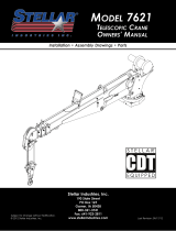
6/-><3-+6988/->398=
From the air pressure switch there are two (2) wires,
red and black, running to the outside of the
compressor housing. Connect the black wire to the
vehicle frame or other suitable ground. Mount a
single throw toggle switch in a convenient location
and connect the red wire from the compressor to
this switch. Connect the other switch terminal to a
fuse holder and then to a 12-volt power supply. A
third wire is required from the air compressor switch
when connecting the speed control into the
system. (See drawing below)
6/-><3-=://.-98><96
An optional electric or electronic speed control
must be used to maintain proper operating speed
of the air compressor. The engine speed control will
automatically increase from idle to preset speed
when engaged and decrease when disengaged.
The electric cable pull speed control Stellar P/N
25740 is used on most gasoline engines. The
electronic speed controls are used only on Ford 7.3
and 6.0L diesel engines. Proper installation
instructions are provided with each system.
C.<+?63-%C=>/7
The hydraulic system consists of the pump, oil
reservoir, filters and hoses. Installed on the
compressor is a valve block assembly that controls
the flow to the hydraulic motor. To this block, a 1/2”
high-pressure hose must be attached. This hose
comes from the hydraulic pumps pressure side. A
3/4” minimum low-pressure return line is connected
to the oil cooler outlet and is routed to the oil
reservoir. American Eagle recommends a sufficient
sized reservoir be provided which includes the
proper suction and return filters. The cooler on the
compressor is designed and sized to cool the air
compressor efficiently. An auxillary oil cooler is
required when additional hydraulically operated
equipment are added to the hydraulic system.
Pressure on the return line exceeding 200 PSI can
and will cause damage to the filter, cooler, and
components of the compressor hydraulic system.

Installation 7
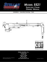
"</==?</%/>>3818=><?->398=
Pressure Setting Instructions:
1. 6A+C==/>>2/53-59?>:</==?</=/>>38103<=> 145 psi minimum/150 psi maximum.
2. After kick out pressure is set, adjust the kick on screw setting at 115 psi minimum/120
psi maximum.
3. Cycle compressor to verify correct settings.
4. For questions about this procedure, please contact Stellar Customer Service.
Kick On (Step 2)
Pressure Setting
Adjustment
Screw
(115-120 psi)
Kick Out (Step 1)
Pressure Setting
Adjustment
Screw
(145-150 psi)
9>/&?<8381+.4?=>7/8>=-</A=-69-5A3=/
38-</+=/=:=3=/>>381=&?<8381+.4?=>7/8>=-</A=
-9?8>/<-69-5A3=/./-</+=/.:=3=/>>381=
+
+
-
-

8 Class 4 Compressor Owner’s Manual
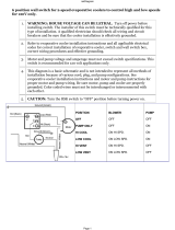
<+85-+=/<9?:&+:/</.%2+0>
==/7,6C<+A381=
CRANKCASE GROUP
.YTQNOITPIRCSEDTRAPMETI.YTQNOITPIRCSEDTRAPMETI
1 C1174 CRANK CASE V480/360 1 20 22209 ROLL PIN 0.19X.63 1
25822GASKET BEARING CARRIER-V480 (.015) 5 21 C0055 OIL INTAKE PLUG 1
35821BEARING CARRIER OIL PUMP V360/V480 1 22 C5416 TUBE OIL PICK UP 1
4C1164BEARING CUP (L44610) 1 23 C0058 OIL INTAKE FILTER SCREEN 1
5 5824 CRANKSHAFT V480 TAPER 1 24 C6273 SNAP RING PISTON PIN N5000-62 1
6C0856 BEARING CONE LM67048 1 25 C4841 PLUG 0.38 NPT SQ HD BLK 1
1S/O 084V REIRRAC GNIRAEB621ENOC GNIRAEB5580C7
8 5820 OIL PUMP DRIVE SLEEVE V480/V360/200 1 27 C6271 FRONT PL GASKET 3
105.X91.0 NIP LLOR71859285825 BEARING SEAL V480 1
C921PMUP LIO GNIRPS0600C01 1163 BEARING CUP (LM67010) 1
11 C0059 OIL PUMP TRANSFER BUSHING 1 30 5813 CAP SCR 0.31-18X0.75 SH 5
1084V KCEHC LIO KCITSPID ELDNAH68622131PMUP LIO0500C21
13 C6275 PORT PLATE 231TEKSAG22210DIPSTICK OIL CHECK V480 1
1211-GNIR'O1400C331 DENIHCAM ETALP TROP2500C41
15 C0054 PORT PLATE COVER GASKET (SMALL) 1 34 5819 GAUGE OIL PSI 1.5 1
1YDOB REHTAERB2600C531REVOC ETALP TROP6262261
17 0485 CAP SCR 0.31-18X1.25 HHGR5 4 36 C5929 COUPLER 0.50 BLK 1
18 6031 SCREW 0.31-18X1.75 SHC 1 37 22868 BREATHER CPRSR .50NPT NY8 1
19 6034 SCREW 0.31-18X1.00 SHC 4 38 C0057 O'RING 2-115 FOR OIL PICKUP TUBE 1
5826

Assembly Drawings 9
<+85-+=/<9?:%><+312>%2+0>
4
1 1
0 1
8
9
7
5
6
7 3
6 3
5 3
1 3
3 3
2 3
8 2
0 3
6 2
7 2
9 2
5 2
3 2
4 2
2 2
8 3
1 2
7 1
6 1
5 1
4 1
0 2
3 1
9 1
3
4 3
8 1
2 1
2
1
9 3
. Y T Q N O I T P I R C S E D T R A P M E T I
1 0 6 3 / 0 8 4 V E S A C K N A R C 4 7 1 1 C 1
5 ) 5 1 0 . ( 0 8 4 V - R E I R R A C G N I R A E B T E K S A G 2 2 8 5 2
1 0 8 4 V / 0 6 3 V P M U P L I O R E I R R A C G N I R A E B 1 2 8 5 3
1 ) 0 1 6 4 4 L ( P U C G N I R A E B 4 6 1 1 C 4
1 S 0 8 4 V T F A H S K N A R C 4 3 8 2 2 5
1 8 4 0 7 6 M L E N O C G N I R A E B 6 5 8 0 C 6
1 E N O C G N I R A E B 5 5 8 0 C 7
1 0 0 2 / 0 6 3 V / 0 8 4 V E V E E L S E V I R D P M U P L I O 0 2 8 5 8
1 0 5 . X 9 1 . 0 N I P L L O R 7 1 8 5 9
1 P M U P L I O G N I R P S 0 6 0 0 C 0 1
1 G N I H S U B R E F S N A R T P M U P L I O 9 5 0 0 C 1 1
1 P M U P L I O 0 5 0 0 C 2 1
1 T E K S A G E T A L P T R O P 5 7 2 6 C 3 1
. Y T Q N O I T P I R C S E D T R A P M E T I
1 D E N I H C A M E T A L P T R O P 2 5 0 0 C 4 1
1 ) L L A M S ( T E K S A G R E V O C E T A L P T R O P 4 5 0 0 C 5 1
1 R E V O C E T A L P T R O P 6 2 6 2 2 6 1
4 5 R G H H 5 2 . 1 X 8 1 - 1 3 . 0 R C S P A C 5 8 4 0 7 1
1 C H S 1.75X 8 1 - 1 3 . 0 W E R C S 1 3 0 6 8 1
4 C H S 0 0 . 1 X 8 1 - 1 3 . 0 W E R C S 4 3 0 6 9 1
1 3 6 . X 9 1 . 0 N I P L L O R 9 0 2 2 2 0 2
1 G U L P E K A T N I L I O 5 5 0 0 C 1 2
1 0 0 . 3 X 8 3 . E K A T N I L I O E B U T 6 1 4 5 C 2 2
1 N E E R C S R E T L I F E K A T N I L I O 8 5 0 0 C 3 2
1 2 6 - 0 0 0 5 N N I P N O T S I P G N I R P A N S 3 7 2 6 C 4 2
1 K L B D H Q S T P N 8 3 . 0 G U L P 1 4 8 4 C 5 2
1 S O / 0 6 3 / 0 8 4 T F 0 8 4 V R E I R R A C G N I R A E B 6 2
. Y T Q N O I T P I R C S E D T R A P M E T I
3 T E K S A G L P T N O R F 1 7 2 6 C 7 2
1 0 8 4 V L A E S G N I R A E B 5 2 8 5 8 2
1 ) 0 1 0 7 6 M L ( P U C G N I R A E B 3 6 1 1 C 9 2
5 H S 5 7 . 0 X 8 1 - 1 3 . 0 R C S P A C 3 1 8 5 0 3
1 0 8 4 V K C E H C L I O K C I T S P I D E L D N A H 6 8 6 2 2 1 3
1 0 8 4 V K C E H C L I O K C I T S P I D 0 1 2 2 2 2 3
1 2 1 1 - G N I R ' O 1 4 0 0 C 3 3
1 5 . 1 I S P L I O E G U A G 9 1 8 5 4 3
1 Y D O B R E H T A E R B 2 6 0 0 C 5 3
1 K L B 0 5 . 0 R E L P U O C 9 2 9 5 C 6 3
1 8 Y N T P N 0 5 . R S R P C R E H T A E R B 8 6 8 2 2 7 3
1 E B U T P U K C I P L I O R O F 5 1 1 - 2 G N I R ' O 7 5 0 0 C 8 3
1 4 / 1 L E E H W Y L F Y E K 7 4 0 3 2 9 3
CRANKCASE GROUP
5826

10 Class 4 Compressor Owner’s Manual
C638./<<9?:
6
5
4
2
3
5
12
9
8
7
10
11
1
12
.YTQNOITPIRCSEDTRAPMETI
2TEKSAG REDNILYC7400C1
2C6364 CONNECTING ROD 200/V480 O/S 2
2084V/002 NOTSIP76753
2084V/002 NIP NOTSIP7636C4
5C6273 SNAP RING PISTON PIN N5000-62 4
6C6360 CYLINDER V480 FINISHED O/S 1
6KCOL 13.0 REHSAW22507
8C0922 CAP SCR 0.31-18X1.00 HHGR5 6
95827 RING OIL V480/200 FLEX DIVIDER 2
10 32931 RING SCRAPER V480/200 H#48638 2
11 32930 RING CPRSN V480/200 BARREL H#38347 2
12 36368 RING OIL V480/200 RING RAIL 4
CYLINDER GROUP

Assembly Drawings 11
/+.<9?:
HEAD GROUP
.YTQNOITPIRCSEDTRAPMETI
1 5808HEAD A/C ALUM V480 O/S 1
2C1586CAP SCR 0.38-16X1.75 SH HEAD BOLT 4
3C0040WASHER HD BOLT STL 1
4 5828WASHER LONG HD BOLT (BRASS) 1
5C1582 BOLT 3.00 HEAD SACKED2
1NEERCS RETLIF7920C6
1MAOF RETLIF5170C7
1RENIATER RETLIF4920C8
1MAOF RETLIF6920C9
10 C0300SCREW #10-32X0.88 NF 3
11 D0887 GASKET VALVE PLATE 200/4801
12 24103 VALVE PLATE SUB ASM O/S 1
13 C0310 GASKET HEAD 143/230/360/4801
14 C0291O'RING-214 VITON 9009-751
Manifold Discharge
.YTQNOITPIRCSEDTRAPMETI
1D0846MANIFOLD V480 DISCHARGE O/S 1
25797 DRAIN COCK-V4801
36000PLUG 0.75 NPT SQ HD CS BLK 1
4C11660.44 X 1.00 PULSATION TANK BOLT 4

12 Class 4 Compressor Owner’s Manual
/+.!:>398=
#5808
Aluminum Air Cooled
Imbedded Filter & 3/4”
Threaded NPT Discharge
#C1632
Aluminum Water Cooled
3/4” Threaded Inlet & 3/4”
Threaded NPT Discharge
#22996
Cast Iron Air Cooled
Imbedded Filter & 3/4”
Threaded NPT Discharge
with Head Unloader Ports
#C1631
Aluminum Water Cooled
Imbedded Filter & 3/4”
Threaded NPT Discharge
#15195
Cast Iron Air Cooled
3/4” Threaded Intake Port
on Top of Head with
3/4” Discharge Port
#3897
Cast Iron Air Cooled
3/4” Threaded Inlet & 3/4”
Threaded NPT Discharge
#23039
Cast Iron Air Cooled
3/4” Threaded Inlet & 3/4“
Threaded NPT Discharge
with Head Unloader Ports

Assembly Drawings 13
!:>398+6/+.'869+./<
PN 23200
ITEM PART DESCRIPTION QTY. ITEM PART DESCRIPTION QTY.
1 22591 BODY HEAD UNLOADER CPRSR 1 6 0220 CAP SCR 0.25-20 X 1.50 HHGR5 5
222599GASKET UNLOADER 1 7 22596 CAP SCR 0.38-16X4.00 SH HEAD BOLT 1
3 22593 PISTON HEAD UNLOADER CPRSR 2 8 C0040 WASHER HD BOLT STL 1
4 22598 O'RING 2-116 HEAD UNLOADER CPRSR 4 9 22597 SPRING PLUNGER PIN UNLOADER CPRSR 2
5 22592 COVER HEAD UNLOADER CPRSR 1 10 22594 PIN PLUNGER HEAD UNLOADER CPRSR 2

14 Class 4 Compressor Owner’s Manual
6CA2//6!:>398=
22997
12” - B GROOVE
22838
14” - DUAL GROOVE

15Assembly Drawings 15
6?>-2!:>398=
C4705
7” DUAL V
C4704
6” DUAL V
C4723
6” - 8 GROOVE
SERPENTINE
8198
6” - 8 GROOVE
24V SERPENTINE
5793
6” - 8 GROOVE
12V SERPENTINE
C4775
7” SINGLE V
5774
6” - 6 GROOVE
12V SERPENTINE
C4762
STRAIGHT BORE

16 Class 4 Compressor Owner’s Manual
%'97:</==9<==/7,6C
.YTQNOITPIRCSEDTRAPMETI
1PN6IWC084V RSRPC8684C1
222686HANDLE DIPSTICK OIL CHECK V480 1
1)063V/032V( KCITSPID938223
1211-GNIR'O1400C4
5C2279 FTG HOSE BARB 0.50 HOSE X 0.50 MNPT 2
6C6235 FTG BRASS ELL 90 DEG A/C 2
100.21X36.0 ESOH691527
2SS 8# PMALC ESOH5664C8
1403 SS 00.4X57.0 ELPPIN878329
1SSARB WOBLE 57.0 GTF6621D01
11 D1264 FTG 0.75-CLOSE RED BRASS NIPPLE 1
12 5480 VALVE CHECK 0.75 STANDARD 1
13 D1267 FTG .75X90 DEG ST EL BRASS 44164 1
14 C4692 FTG 0.75 JIC-ML NPT 12CTX 90 DEG EL 1
15 C0863 SWITCH PRES COMPRESSOR 1
16 C5559 FTG ADAPT 1/8ML-1/4FM NPT 1404-2-4 1
1ELPPIN XEH 52.0 GTF6755C71
1SEE PAGE 15 FOR CLUTCH OPTIONS81
19 D0240 FTG ELL 0.13 CPRSN TUBE TO NPT 1
20 25448 TUBE COPPER 0.25X9.00 SUH-60 1
18
8
6
7
8
6
2
3
4
20
10
9
5
11
12
13
14
16
17
15
19
1
COMPRESSOR ASSEMBLY
/