Page is loading ...

ECEC32003200
4281842818
!$%%"!($$ '#&!$(#%$
)
Stellar Industries, Inc.
190 State Street
PO Box 169
Garner, IA 50438
800-321-3741
Fax: 641-923-2811
www.stellarindustries.com
Last Revision: 09/06/12
Subject to Change without Notification.
© 2012 Stellar Industries, Inc.

EC3200 Manual Revisions
Date of Revision Description of Revision
Section Revised

Table of Contents
Find a Dealer Near You:
http://www.stellarindustries.com/pages/dist/distsearch.htm
For Technical Questions, Information, Parts, or Warranty, Call Toll-Free at
800-321-3741
Hours: Monday - Friday, 8:00 a.m. - 5:00 p.m. CST
Or email at the following addresses:
Technical Questions, and Information [email protected]
Order Parts [email protected]
Warranty Information [email protected]
Table of Contents
Chapter 1 - Specifications . . . . . . . . . . . . . . . . . . . . . . . . . . 1
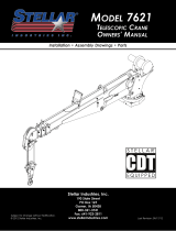
Capacity Chart - Decal PN 42817. . . . . . . . . . . . . . . . . . 2
Chapter 2 - Installation . . . . . . . . . . . . . . . . . . . . . . . . . . . . . 3
Installation Overview . . . . . . . . . . . . . . . . . . . . . . . . . . . . . 4
Flatbed Body Reinforcement . . . . . . . . . . . . . . . . . . . . . . 5
EC3200 Mounting Detail . . . . . . . . . . . . . . . . . . . . . . . . . . 5
EC3200 Installation Drawing . . . . . . . . . . . . . . . . . . . . . . . 6
Hydraulic Kit - PN 42799. . . . . . . . . . . . . . . . . . . . . . . . . . . 7
Control Kit - PN 42804 . . . . . . . . . . . . . . . . . . . . . . . . . . . . 8
EC3200 Wiring Diagram (Two Battery) . . . . . . . . . . . . . . 9
EC3200 Wiring Diagram (One Battery) . . . . . . . . . . . . . 10
Valve Bank Drawing . . . . . . . . . . . . . . . . . . . . . . . . . . . . . . . 11
Stability Procedure. . . . . . . . . . . . . . . . . . . . . . . . . . . . . . 12
Stability Capacity Chart . . . . . . . . . . . . . . . . . . . . . . . . . 13
Decal Kit Placement - PN 42816 . . . . . . . . . . . . . . . . . . 14
Chapter 3 - Assembly Drawings. . . . . . . . . . . . . . . . . . . . . 15
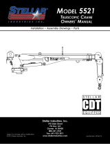
Base Assembly - PN 42525 . . . . . . . . . . . . . . . . . . . . . . . 15
Base Assembly (Narrow Version) - PN 44613. . . . . . . . . 16
Mast Assembly - PN 42787 . . . . . . . . . . . . . . . . . . . . . . . 17
Main Boom Assembly - PN 42512. . . . . . . . . . . . . . . . . . 18
Extension Boom Assembly - PN 42520 . . . . . . . . . . . . . . 19
Cable & Hook Assembly - PN 42781 . . . . . . . . . . . . . . . 20
Radio Transmitter Assembly . . . . . . . . . . . . . . . . . . . . . . 21
Chapter 4 - Replacement Parts . . . . . . . . . . . . . . . . . . . . . 23

EC3200 Owner’s Manual
This page intentionally left blank.

Specifications
Chapter 1 - Specifications
Model EC3200 Crane
SPECIFICATION SHEET
Crane Rating: 11,500 ft-lb (1.59 TM)
Standard Boom Length: 7’ (2.13 m) from CL of Crane
Boom Extension: 1st stage: Hydraulic 48" (121.9 cm)
2nd stage: Manual 48" (121.9 cm)
Maximum Horizontal Reach: 15’ (4.57 m) from CL of Crane
Maximum Vertical Lift: 16’ 2” (4.93 m)
(from crane base)
Boom Elevation: -5 to +80 degrees
Stowed Height: 24” (61.0 cm)
(crane only)
Mounting Space Required: 18” x 15” (45.7 x 38.1 cm)
Approximate Crane Weight: 730 lbs (331 kg)
Controls: Radio control standard for all functions.
Winch Specifications
Rope Length: 65 ft (19.8 m)
Rope Diameter: 7/32" (.56 cm)
Line pull speed: 15 ft/min (4.6 m/min)
Max. single part line: 1600 lbs (725 kg)
Max. double part line: 3200 lbs (1450 kg)
Rotation: 410 degree power
(worm gear)
Lifting Capacities: 1625 lbs @ 7’ (737 kg @ 2.1 m)
905 lbs @ 11’ (410 kg @ 3.35 m)
640 lbs @ 15’ (290 kg @ 4.6 m)
Power Supply Required: 12 volt power unit
(2.0 gpm @ 2600 psi)
(7.57 lpm @ 179 bar)
*Subject to change without notification

EC3200 Owner’s Manual
3’
.914 M
0’
6’
1.83 M
7’
2.13 M
11’
3.35 M
15’
4.57 M
0’
3’
.914 M
6’
1.83 M
9’
2.74 M
12’
3.66 M
15’
4.57 M
16’2”
4.92 M
Reach in Feet/Meters
Capacity in Pounds/Kilograms
Weight of load handling devices are
part of the load lifted and must be
deducted from the capacity.
EC3200
PN 42817
Maximum 1 - part line capacity is
1600lbs (725kg). For greater loads,
use 2 - part line.
15º
30º
45º
60º
75º
80º
410 kg
905 lbs
1490 lbs
3200 lbs
1710 lbs
775 kg
3200 lbs
1450 kg
1450 kg
2415 lbs
862 kg
1095 kg
1900 lbs
3200 lbs
1450 kg
675 kg
1372 kg
1450 kg
3200 lbs
1450 kg
3200 lbs
973 kg
2145 lbs
703 KG
*1550 lbs
*3200 lbs
1450 kg
*3025 lbs
890 lbs
290 kg
640 lbs
550 kg
353 kg
780 lbs
492 kg
1085 lbs
404 kg
1215 lbs
1090 lbs
495 kg
83.69
®
710 kg
1565 lbs
Capacity Chart - Decal PN 42817

Installation
Chapter 2 - Installation
General Installation
This chapter is designed to serve as a
general guide for the installation of a Stellar
EC3200 Crane on a Stellar Service Body.
Each installation is considered unique so
certain portions of this chapter may or may
not apply to your direct application. If a
question should arise during the installation
process, please contact Stellar Customer
Service at (800) 321 3741.
This crane is designed for use with a Stellar
Service Body installed on a vehicle that
meets the minimum chassis requirements of
the crane. It is the installer’s responsibility to
assure that the crane is mounted on a
platform that will support the maximum
crane rating of this crane.
Notice:
PTO and Pump installation instructions are
provided by the corresponding
manufacturers. For more information on
which PTO and Pump fit your application,
please contact your local Stellar Distributor
or Stellar Customer Service.
Installation Notice
According to Federal Law (49 cfr part 571),
each final-stage manufacturer shall
complete the vehicle in such a manner that
it conforms to the standards in effect on the
date of manufacture of the incomplete
vehicle, the date of final completion, or a
date between those two dates. This
requirement shall, however, be superseded
by any conflicting provisions of a standard
that applies by its terms to vehicles
manufactured in two or more stages.
Therefore, the installer of Stellar cranes and
bodies is considered one of the
manufacturers of the vehicle. As such a
manufacturer, the installer is responsible for
compliance with all applicable federal and
state regulations. They are required to
certify that the vehicle is in compliance with
the Federal Motor Vehicle Safety Standards
and other regulations issued under the
National Traffic and Motor Vehicle Safety
Act.
Please reference the Code of Federal
Regulations, title 49 - Transportation, Volume
5 (400-999), for further information, or visit
http://www.gpoaccess.gov/nara/index.html
for the full text of Code of Federal
Regulations.
Notice: Read this Page Before Installation of the Crane
Important: When installing welder units to the service
bodies, it is highly recommended that a surge
protector is installed on the chassis batteries to protect
the crane radio receiver, wiring and other electronic
devices from an unexpected electrical spike or surge.
Failure to do so could result in extensive damage to
the service body and crane electrical circuit.

EC3200 Owner’s Manual
Front of Truck
Installation Overview
1. Determine that the mounting location for the EC3200 crane is at least 18” x 15” (45.7 x 38.1 cm).
2. Use the detail on the following page to drill .938” diameter holes into the mounting plate. Run tap on the
threads of the base to be sure they are clean.
3. Use a crane or lifting device capable of lifting the weight of the Stellar crane. The Stellar EC3200 weighs
approximately 800 lbs (360 kg). Note: cranes are shipped with rotation positioned at 180 degrees from
normal stowed travel position. This will allow for easy installation of the crane and permanent connection
of all hydraulic and electrical components prior to repositioning into the crane saddle.
4. Connect straps or chain from the lifting device to the main boom of the Stellar EC3200.
5. Use four (4)
7
⁄8” x 1-
3
⁄4” #8 bolts and four (4) #8
7
⁄8” flat washers.
6. Install a washer on each bolt.
7. Apply Loctite Thread locker #277 to the bolts.
8. Using the lifting device, lower the Stellar EC3200 just above the crane compartment and start the bolts.
Have someone assist in leveling the crane.
9. Secure the crane using the mounting hardware provided. Note: longer or shorter cap screws may be
required – recommended thread engagement into crane base is 0.75” – use grade 8, zinc plated cap
screws only.
10. Torque the cap screws to 454 ft-lbs.
11. Remove supporting crane.
12. Hook-up hydraulics and electrical using the schematics provided at the end of this chapter.
Note: If questions should arise during any portion of this installation,
please contact Stellar Customer Service at (800) 321-3741.
WARNING!
The use of this crane on a
body not capable of handling
the loads imposed on it may
result in serious injury or
death.

Installation
HOLE MOUNTING DETAIL
FRONT
7.38
5.00
10.00
14.75
3.00
EC3200 Mounting Detail
TUBE 4X2X0.38
TRUCK FRAME
TUBE 4X2X0.38
3/8 PLATE
TUBE 2X2X0.38(TYP 4)
Flatbed Body Reinforcement
HOLE MOUNTING DETAIL
FRONT
7.38
14.75
5.00
10.00
Standard
Narrow
Base
If it has been determined that the destination
body won’t support the crane with a fully
rated load, the body must be reinforced.
Use 1/4” fillet welds and an ASWS qualified
welder to proceed as shown in this drawing:
Note: Tubing must be
at least 4” x 2” x 0.38”
(Except where noted)

EC3200 Owner’s Manual
IS PART OF THIS KIT
STABILITY DECAL P/N 16881
NOTE:
2
3
.YTQNOITPIRCSEDTRAPMETI
2 18041 WASHER 0.88 SAE FLAT YELLOW GR94
3 51377 CAP SCR 0.88-9X2.00 HHGR94
Stowed Position
EC3200 Installation Drawing
NOTICE!
Route hoses correctly to ensure
they do not become pinched or
crushed during installation.

Installation
BOOM UP
BOOM DOWN
MAIN UP
ROTATI ON CCW
ROTATI ON CW
MAIN DOWN
EXT IN
EXT OUT
ROTATION CW
ROTATION CCW
ROTATION
2
05 43847
ITEM
01
02
03
04
42980
42800
PART No.
42983
42981
06
07
09
08
10
42982
42984
C1111
PN 42799
FTG ADAPT MSTR/FSTR 10-6 F5OG5
HOSE KIT 3315 CRANE (incl:2-11)
DESCRIPTION
HOSE-HYD .25 X 20
HOSE-HYD .25 X 22
HOSE-HYD .25 X 23
HOSE-HYD .25 X 19
HOSE-HYD .25 X 42
HOSE-HYD .25X 43
QTY
1ref
1
1ref
1ref
1ref
1ref
1ref
13
11
12
14
15
49315
D1291
C4922
3861
16
MAIN
EXTENSION RETRACT
EXTENSION EXTEND
EXT
FTG ADAPT 4-F5OLO-S
FTG ADAPT 4-6 F5OLO-S
FTG ML FM O'RING 90 DEG
SWITCH PRES OVERLD CD-11C-2900R/WD
1
4
8
1
02 06 07
12 12
03
12 12
12 12
04
05
12
10
12
10
13
14
11
11
11
11
Hydraulic Kit - PN 42799

EC3200 Owner’s Manual
NOTE: P/N 47409 INCLUDES
HARNESS & WINCH CONTROLLER
7,8
9
POWER
GROUND
OPT1
OPT2
WINCH UP RELAY
1
WINCH DOWN
POWER 12 V
3
POWER UNIT SIGNAL
POWER 12 V
2
4,5,6
SWITCH
4,5,6
A2B
PRESSURE SWITCH
RADIO CNTRL ASM 5 FCTN ON/OFF
SWITCH PUSH BUTTON 9216-03
WIRE HARNESS 3315 MULTI FUNCTION VB
PART No.ITEM
42976
17771
42805
03
01
02
DESCRIPTION
COVER SWITCH EC3200
SWITCH MOM SPST 20A
CABLE SEAL 18-20 PACKARD 39000
CONNECT 2 PIN SHROUD PACKARD
CONTACT M TERM SHROUD 14-16 3103406 9756
8384
9752
05
04
47409
47410
08
07
WIRE HARNESS 3315 MULTI FUNCTION VB
FUSE HOLDER 46039
FUSE 250 AMP 4627611 36436
47092
3252310
09
12
QTY
1
1
1
4
4
2
1
1
1
1
1
MAIN
CONTACT
GROUND
PN 42804
7
6
8
5
A
109
4 3
11
2
12
1
87A
30
86
85
87
A
B
B
A
8
5
12
1
B
11
2
10
3
9
4
A
B
B
A
7
6
A
B
B
A
A
B
B
A
A
B
B
A
A
B
B
A
ROT
CW
ROT
CCW
INNER
DOWN
INNER
UP
EXT
IN
EXT
OUT
A
B
A
B
WINCH
DOWN
GROUND
WINCH
UP
REPLACEMENT CONTROLLER
STELLAR P/N 42821
B
A
B
A
B
A
C
Winch
Power
Unit
Control Kit - PN 42804

Installation
+
-
FUSE 250 AMP
(STELLAR SUPPLIED)
UNDERHOOD
TRUCK BATTERY
MASTER
250 AMP
AUX BATTERY
-
+
CRANE
COMPARTMENT
CAB OR CRANE
10 AMP
POWER
SWITCH
START MOTOR
SOLENOID
GROUND POST
CRANE HARNESS
GROUND
GROUND
LOCATE AUX BATTERY AS
CLOSE TO CRANE AS POSSIBLE
GROUND
POWER
OPT1
OPT2
SWITCH
(NOT SUPPLIED)
POWER SOURCE FOR
RADIO REMOTE
Torque Spec
Large Nuts: 35 in-lbs
Small Nuts: 15 in-lbs
FUSE 250 AMP
(STELLAR SUPPLIED)
Recommended Wire Sizes:
EC3200 - #2
EC4000 - #2
EC5000 - #2
EC6000 - 1/0
EC3200 Wiring Diagram (Two Battery)

EC3200 Owner’s Manual
+
-
FUSE 250 AMP
(STELLAR SUPPLIED)
UNDERHOOD
TRUCK BATTERY
CRANE
COMPARTMENT
CAB OR CRANE
10 AMP
POWER
SWITCH
START MOTOR
SOLENOID
GROUND POST
CRANE HARNESS
GROUND
GROUND
GROUND
POWER
OPT1
OPT2
POWER SOURCE FOR
RADIO REMOTE
Torque Spec
Large Nuts: 35 in-lbs
Small Nuts: 15 in-lbs
SAFETY BRAKE
87A
30
86
85
87
Note:
With a single battery configuration,
operating the crane when the truck
is not running will drain the truck battery.
Recommended Wire Sizes:
EC3200 - #2
EC4000 - #2
EC5000 - #2
EC6000 - 1/0
EC3200 Wiring Diagram (One Battery)

Installation
ROT
CCW
ROT
CW
INNER
UP
INNER
DOWN
EXT
OUT
EXT
IN
Valve Bank Drawing

EC3200 Owner’s Manual
Definition of Stability for the Stellar Telescopic Crane Products:
A truck is stable until the load cannot be lifted off the ground with the winch, without
tipping over the truck. Every Stellar crane installed must be tested for stability to
determine the actual load capacity of the final truck package. The actual test data
must be recorded and supplied with the truck at the time of in-service and should be kept
with the truck at all times. The following procedure will test the truck package for stability
and will provide a stability capacity chart. The load limit information shown on the
stability capacity chart is formulated on 85% tipping.
Set Up:
1. Locate the truck on a test course in position for loading and engage travel brakes.
2. Set stabilizers so that they make contact with firm, level footings.
3. Operate the crane under partial load to assure operator proficiency and proper
machine function.
Test Procedure
1. Rotate the crane into Zone 1 position.
2. With the crane fully retracted and the boom horizontal, winch the test weight off the
ground. Note: Keep weight within six inches of the ground at all times.
3. Extend the boom outward until full extension has been reached or until the truck
becomes unstable (Again, use the winch to keep the weight within six inches of the
ground.)
4. If the boom goes full extension without becoming unstable, the crane is termed stable
for this zone and 100% can be written in the Zone 1 data box.
5. If the truck becomes unstable prior to going full extension, retract the boom until the
truck becomes stable and measure the horizontal reach in this position (center of
rotation to boom tip). This is the stable horizontal reach for this zone. Stable horizontal
reach divided by Maximum horizontal reach multiplied by 100 equals the percentage
of rated capacity for this zone. Use the following formula to determine the percentage
of rated capacity:
6. Record this number in the data box for Zone 1. This is the revised capacity due to
stability for this zone.
7. Repeat this procedure for each zone until the worksheet is completed.
8. This is the revised capacity based on stability of this package.
EC3200 Stability Data
Max Horizontal Reach: 180” (From the center of rotation to boom tip)
Stability Test Weight: 755 lbs.
Stability Procedure

Installation
STABILITY CAPACITY CHART
Stability Capacity Chart

EC3200 Owner’s Manual
PART No.
DESCRIPTION
ITEM
QTYQTY
PART No.ITEM
DESCRIPTION
DECAL-ELECTROCUTION 2x2.75
DECAL-ELECTROCUTION 4.5x7.5
DECAL ASME/ANSI B30.22/B30.5
4190
*10
DECAL-DANGER
09
*08
*06
07
*05
*03
*04
02
01
C4540 DECAL-DANGER
DECAL CAPACITY
DECAL-ELECTROCUTION 5x13
DECAL IDENTIFICATION
15172
42818
42817
C4545
DECAL-DANGER
DECAL-ROTATE/GREASE
DECAL-DANGER
C4544
4186
9188
4189
15
14
*12
*13
*11
13819 DECAL-ANGLE INDICATOR SS
DECAL-DANGER O.R.
DECAL ANGLE INDICATOR CS
DECAL-DANGER MOVING O.R.C5918
C4795
13820
C1179
1
1
15171
25
DECAL GREASE WORM DRIVE BEARINGS
DECAL-STELLAR 4x9.5
DECAL HOISTING PERSONNEL
DECAL-CRANE STOWING
DECAL-TWO BLOCKING
DECAL-STELLAR 2x4.5
DECAL MANUAL EXT
DECAL-DIESEL
DECAL-SERVICE
1C0568
*20
2
*16
1
*17
4
*19
2
*18
12451
C5910
12452
C5911
1
*21
1
22
1
24
1
*23
4214
12300
C4541
2
1
1
3
1
1
1
1
DECAL VB CONTROL EC3200
*USE THESE DECALS WITH BODY PACKAGE
DECAL STELLAR MADE IN THE USA
DECAL SNATCH BLOCK CAP 3 TON
DECAL WARNING OVERLOAD DEVICE
DECAL WARNING MANUAL OVERRIDES
DECAL CAUTION STOW HOOK
35234
30
1
2
26
2
27
29
1
2
28
24712
25159
42819
28256
**31
**THESE DECALS NOT INCLUDED WITH THE DECAL KIT
42820
1
1
1
1
1
1
18472 DECAL MANUAL OPERATION 1
PN 42816
30
31
26
9
24
27
29
01
28
14,15
25
22
7
03
02
3030
2020
5050
6060
7070
4040
1010
00
D1196D1196
IndicatorIndicator
8080
AngleAngle
ECEC32003200
4281842818
Decal Kit Placement - PN 42816

Assembly Drawings
11
5
3
4
2
6
1
8
7
9
10
9
12
.YTQNOITPIRCSEDTRAPMETI
10023CE ESAB487241
241640BEARING SWING DRIVE 170-00058-1 1
13 MOTOR 80CC EC3200 YMPH-80-H2(R)-K-S-B62487
4 21151GASKET MOTOR 008-10056-1 1 ref
2HS 52.1X31-05.0 RCS PAC7031D5
6 30750 CAP SCR 0.50-13X3.50 HHGR813
10023CE GNIDILS POTS597247
318RG TALF 05.0 REHSAW0970D8
9D1345 FTG CPRSN 0.12NPT/0.25 TUBE2
10 D1810 TBE AIR SAEJ844 TYPE A .25 (RM)1
131.0 EPIP RELPUOC GTF6522C11
12 56589 ZERK 1/8 NPT STRAIGHT LONG THREAD 1
PN 42525
Base Assembly - PN 42525
Chapter 3 - Assembly Drawings

EC3200 Owner’s Manual
.YTQNOITPIRCSEDTRAPMETI
1
1
WORRAN 0023CE ESAB416441
3
241640BEARING SWING DRIVE 170-00058-1 1
4 21151GASKET MOTOR 008-10056-1 1 ref
5D1307 CAP SCR 0.50-13X1.25 SH2
6 30750 CAP SCR 0.50-13X3.50 HHGR813
10023CE GNIDILS POTS597247
318RG TALF 05.0 REHSAW0970D8
9D1345 FTG CPRSN 0.12NPT/0.25 TUBE2
10 D1810 TBE AIR SAEJ844 TYPE A .25 (RM)1
131.0 EPIP RELPUOC GTF6522C11
12 56589 ZERK 1/8 NPT STRAIGHT LONG THREAD 1
11
5
3
4
2
6
1
8
7
10
9
12
PN 44613
MOTOR 80CC EC3200 YMPH-80-H2(R)-K-S-B62487
Base Assembly (Narrow Version) - PN 44613
/