Page is loading ...

TABLE OF CONTENTS
Table of Contents ..........................................................................1
Safety Symbols .............................................................................2
Safety Instructions........................................................................3
GR2540 Specifications..................................................................5
GR2540LR Specifications.............................................................6
Compressor Description ..............................................................7
Compressor Parts Description.....................................................8
Set Up...........................................................................................10
Operation.....................................................................................12
Maintenance ................................................................................13
GR2540 Schematic...................................................................... 14
GR2540 Parts List - Pump .....................................................15-16
GR2540LR Schematic.................................................................17
GR2540LR Parts List - Pump.................................................18-19
Troubleshooting..........................................................................20
Storage.........................................................................................22
Warranty....................................................................................... 23
WARNING
This manual contains important safety and operating instructions that must be followed.
You must read and understand this manual before operating this compressor. Failure
to follow all instructions can result in serious injury to operator and bystanders, or
damage to compressor and attachments.
1

SAFETY SYMBOLS
The safety symbols used on the compressor’s safety labels and in this manual provide an
important visual reminder of basic safety rules, and the hazards that may arise if all safety and
operating instructions are not followed. Make sure you understand the meaning of each of
these symbols, and protect yourself and others by obeying all safety and operating instructions
on warning labels and in this manual.
SYMBOL DESCRIPTION
SAFETY ALERT SYMBOL
Calls attention to important safety information and provides an alert to
potential safety hazards.
HOT SURFACE HAZARD
Hot surfaces can cause serious burn injury if touched. Let unit cool before
handling.
MOVING PARTS/ENTANGLEMENT HAZARD
Contact with moving parts can cause serious injury. Keep guards and
protective covers in place.
INHALATION HAZARD
Compressed air can contain carbon monoxide or other harmful gases. Do
not use compressor to provide air for breathing.
BURST HAZARD
Over-pressurization caused by tampering with controls can cause serious
injury or death from explosion.
SHOCK HAZARD
Contact with live electrical components can cause shock, serious injury, or
death from electrocution. Use a properly grounded power source.
EXPLOSION HAZARD
Electrical sparks from unit can ignite flammable liquids and vapors. Use
compressor in a well ventilated area free from explosive vapors.
FIRE HAZARD
Keep compressor 20’ feet away from spray area when spraying flammable
materials. Operate unit away from obstructions that could block ventilation.
HIGH PRESSURE AIR HAZARD
Release of pressurized air can cause serious injury if directed against body.
Never use air pressure higher than recommended for tool or accessory.
2

SAFETY INSTRUCTIONS
WEAR ANSI Z87.1 APPROVED EYE PROTECTION - Always wear approved eye protection equipment that
provides both front and side eye protection when operating or servicing the compressor.
DO NOT EXCEED MAXIMUM RECOMMENDED OPERATING PRESSURE OF AIR-POWERED TOOLS OR
OTHER EQUIPMENT BEING USED - Spray guns and other low to medium pressure equipment can burst,
causing serious injury to user and bystanders. Read and follow all manufacturers' pressure recommendations
before connecting tools, sprayers, or other equipment to compressor. Use extreme care when using the
compressor with tires, inner tubes, and other inflatables, as excessive pressure or rapid inflation can cause these
items to burst.
CONNECT COMPRESSOR POWER CORD ONLY TO A PROPERLY GROUNDED POWER OUTLET USING
AN APPROVED 3-PRONG GROUNDED EXTENSION CORD - Using an improperly grounded outlet or extension
cord can result in shock or electrocution. Electrical wiring, outlets, extension cords, and current protection
devices such as fuses and circuit breakers must meet local electrical and safety codes, as well the requirements
of the National Electrical Code. A ground-fault circuit interrupter (GFCI) device may be required for compressor
use outdoors, in garages, and in damp locations.
USE AN EXTENSION CORD THAT IS PROPERLY SIZED - Using an undersize cord can result in overheating of
cord and short-circuiting, resulting in fire and damage to property. Use a UL-listed extension cord rated to safely
handle the power requirements of the compressor.
DO NOT OPERATE IF FLAMMABLE VAPORS ARE PRESENT - The electric motor and pressure switch may
produce sparks, which can ignite flammable vapors and cause fire or explosion. Flammable vapors from
gasoline, solvents, adhesives, and other chemicals may drift some distance from the source, or build up in low
areas. Operate the compressor only in well-ventilated areas that are free of flammable vapors.
DO NOT OPERATE IN THE RAIN OR IN WET AREAS - Operating an electric compressor in wet conditions can
result in severe shock or electrocution. Operate only in dry conditions, using a properly grounded power outlet
that conforms to local and national electrical code requirements. An outlet with ground-fault circuit interrupter
(GFCI) protection is recommended for use outdoors or in garages, and may be required by local electrical codes.
DO NOT TOUCH COMPRESSOR HEAD OR TUBING WHEN UNIT IS OPERATING - Normal compressor
operation will cause tubing and other components to become extremely hot. Contact with hot parts can cause
serious burns. Allow unit to cool before handling or performing service.
3

SAFETY INSTRUCTIONS
NEVER DIRECT COMPRESSED AIR AT ANY BODY PARTS - Compressed air can penetrate skin, or force dirt
and debris into eyes, causing serious injury. Never place hands or body parts over the air discharge opening of
a pressurized nozzle or fitting. Use care when connecting and disconnecting air hose to attachments, pneumatic
tools, and other air-powered devices.
KEEP FLAMMABLE SPRAYS AWAY FROM SPARKS AND OTHER SOURCES OF IGNITION - Spraying
flammable liquids such as oil-base paints, sealers, and finishes near sparks, open flame, and other sources of
ignition such as pilot lights, appliances, water heaters, furnaces, etc. can result in explosion and fire. Turn off all
pilot lights, and avoid using electrical appliances, heaters, torches, and other equipment that may produce sparks
or flame. Keep compressor as far away from spraying area as possible by using an air hose of sufficient length
to prevent spray mist from being ignited by electrical sparks from compressor operation.
DO NOT TAMPER WITH COMPRESSOR PRESSURE SWITCH SETTINGS - The pressure switch settings set at
the factory provide the maximum safe operating pressure recommended for this compressor. Altering these
settings can result in over-pressurization, risk of tank, hose, and pneumatic equipment failure, and serious injury
to operator and bystanders.
USE AIR HOSE RATED FOR 150 PSI OR GREATER - Air hose must be rated to safely handle maximum
compressor pressure. Air hose that does not meet minimum pressure requirements can rupture, releasing high
pressure air. Replace a cracked or leaking air hose immediately to prevent serious injury from contact with high
pressure air streams.
DISCONNECT POWER CORD AND RELIEVE TANK PRESSURE BEFORE SERVICING UNIT – Never perform
service or maintenance on any part of the compressor while the unit is pressurized or connected to power. The
compressor can start automatically, causing serious injury. Open tank drains slowly to allow air to escape, and
keep clear of air stream.
DO NOT MODIFY COMPRESSOR – Altering the compressor in any way may create a serious safety hazard, and
result in serious injury to operator and bystanders. If compressor does not work properly, stop using unit
immediately. Return unit to an authorized service center for repairs if problem cannot be remedied by following
troubleshooting instructions in this manual.
4

SPECIFICATIONS GR2540
DESCRIPTION SPECIFICATION
Motor
Horsepower 2.5 (Peak)
Voltage 115V
Amperage 14
Hz 60
Phase Single
RPM 3450
Capacity
Tanks 1
Air Storage Capacity 4 Gallons
Maximum Air Pressure 150 PSI
CFM 5.7 cfm @ 40 PSI
4.5 cfm @ 90 PSI
Pressure Switch Settings
Pressure Switch - ON 110 PSI
Pressure Switch - OFF 150 PSI
Compressor Pump
Cylinders 1
Compression Stage 1
Lubrication Splash
Oil Type Compressor Oil SAE 30W (ISO 100)*
Crankcase Aluminum
Bearings Ball
Cylinder Cast Iron
Valves Stainless Steel Reed
Head Aluminum
Filter Canister
Dimensions
Weight 88 Lbs.
Shipping Weight 92 Lbs.
Size ( L X W X H) 23.6" X 22" X 20"
*PROVIDED WITH UNIT
5

SPECIFICATIONS GR2540LR
DESCRIPTION SPECIFICATION
Motor
Horsepower 2.5 (Peak)
Voltage 115V
Amperage 12
Hz 60
Phase Single
RPM 1725
Capacity
Tanks 1
Air Storage Capacity 4 Gallons
Maximum Air Pressure 150 PSI
CFM 5.3 cfm @ 40 PSI
4.2 cfm @ 90 PSI
Pressure Switch Settings
Pressure Switch - ON 110 PSI
Pressure Switch - OFF 150 PSI
Compressor Pump
Cylinders 1
Compression Stage 1
Lubrication Splash
Oil Type Compressor Oil SAE 30W (ISO 100)*
Crankcase Aluminum
Bearings Ball
Cylinder Cast Iron
Valves Stainless Steel Reed
Head Aluminum
Filter Canister
Dimensions
Weight 88 Lbs.
Shipping Weight 92 Lbs.
Size ( L X W X H) 23.6" X 22" X 20"
*PROVIDED WITH UNIT
6

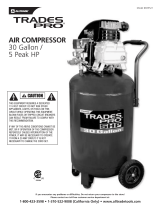
COMPRESSOR PARTS DESCRIPTION
KEY DESCRIPTION FUNCTION
1 Heavy Duty Power Cord Provides power to compressor motor
2 Frame Protects compressor components
3 Compressor Pump Compresses air
4 Reset Switch Protects motor from overloads
5 Dipstick (not on GR254LR) Used to check oil level in pump crankcase
6 Hex Head Wheel Bolt Secures wheels to compressor frame
7 Wheel Assembly Large pneumatic tires allow easy rolling
8 Safety Relief Valve Releases excessive air pressure from tank
9 Air Storage Tank Stores compressed air
10 Rubber Foot Provides stable footing, reduces vibration
11 Handle Latch Secures handle position for easy transport
12 Air Tank Drain Allows moisture to be drained from tank
13 Handle Extends for ease of transport
14 Air Outlet Fittings (2) Allows quick connection of air hoses
15 Regulator Control Knob Adjust discharge air pressure setting
16 Tank Air Pressure Gauge Indicates air pressure in storage tank
17 Air Outlet Pressure Gauge Indicates air pressure at air outlet fittings
18 Compressor Top Plate Protects compressor components
19 On-Off Switch Turns compressor on and off
20 Tank Warning Label Provides important safety information
21 Cooling System Cools compressor components
22 Motor Shroud Protects motor and compressor
23 3-Prong Grounding Plug Safely grounds equipment when properly
connected to a grounded power source.
24 Motor Label Provides important motor information
25 Air Filter Filters intake air to remove dust and debris
26 Power Cord Retainer Secures power cord for storage
8

SET UP
WARNING:
Before being used for the first time, your new compressor requires a simple set-up procedure
that will help your unit deliver years of trouble-free service. Failure to follow all initial set-up
instructions may result in serious damage to your compressor, property damage, or serious
injury to operator and bystanders. Do not start compressor until all set-up steps have been
performed.
1. Remove compressor and wheel assemblies
from carton.
2. Install wheels on wheel mounts at bottom of
frame using hex head wheel bolts. Tighten
bolts securely with 1-1/4” wrench.
3. Unscrew shipping plug from crankcase. Add
non-detergent oil to compressor and check oil
level in sight glass or with dipstick. Oil level
must be between “L” (Low) and “H” (High)
marks on flat area of dipstick. Crankcase
capacity is ll.8 oz. (350 ml). Use chart below
for correct viscosity:
Air Temperature Viscosity
14 – 40 F SAE 20 (ISO 68)
40 – 80 F SAE 30 (ISO 100)
9

4. Install dipstick in crankcase, and tighten
securely before starting compressor. Make
sure black seal is in place between dipstick and
crankcase to prevent loss of oil during
compressor operation or movement.
5. Check power outlet circuit for correct capacity.
Compressor requires 120V, Single Phase, 14
Amps, 60 Hz. Fuses or circuit breakers must
be rated accordingly.
6. Use an extension cord with 3-prong grounding
plug. Extension cord must be sized to prevent
power loss and overheating of the motor:
Cord Length Wire Gauge Size
Up to 25 ft. 12 ga.
Up to 100 ft. 10 ga.
Up to 150 ft. 8 ga.
Up to 250 ft. 6 ga.
7. Pull handle out until locking hole in handle is
aligned with locking pin on base of compressor.
Lock handle in extended position with locking
pin, and use handle to wheel compressor to
desired area of operation.
8. Position compressor on a secure, stable
surface, no more than 10 degrees off level.
9. Plug power cord in, and unscrew Air Tank Drain
at the bottom of the air tank. Start compressor
by moving On/Off lever up to the “ON” position.
Allow compressor to run for 10 minutes without
stopping. Watch for excessive vibration or
unusual noise while compressor motor is
running. If unit vibrates excessively or makes
unusual noise, shut compressor off by moving
On/Off lever to “OFF” position. Refer to
trouble-shooting chart for corrective action. If
no excessive vibration is noted, tighten the Air
Tank Drain, allow unit to fill the air tanks, and
proceed to step 10.
10. Check operation of Pressure Relief Valve by
pulling release ring out to exhaust air pressure
from tank. Release ring and allow pressure
relief valve to reseat. Contact your dealer if
Pressure Relief Valve does not operate
properly.
11. Compressor is now ready for regular operation.
10

OPERATION
Operating Compressor
1. Move On/Off lever to the "OFF" position.
C
D
D
B
A
2. Plug the power cord into the power
receptacle.
3. Move On/Off lever to the "ON" position.
4. Leave compressor in “ON” position while in
use.
5. To stop compressor, move On/Off lever to the
"OFF" position. DO NOT stop compressor
by unplugging power cord.
6. Adjust outlet air pressure to desired setting by
turning pressure regulator knob “C.” Turn
knob clockwise (+) to increase air pressure,
counterclockwise (-) to decrease air pressure.
Outlet air pressure is indicated by gauge (B).
Tank pressure is indicated by gauge (A)
7. Connect air hoses to quick-connect fittings (D)
using a male quick-connect fitting. To
connect air hose simply insert male hose
connector. To release air hose, push hose
fitting in, push back outer ring on compressor
fitting, and pull male hose connector out.
WARNING
High pressure air will escape when hose is
disconnected. Keep face away from fittings to
prevent dirt and debris from being blown into eyes.
Always wear safety glasses with side shields to
protect eyes when using compressor.
11

MAINTENANCE
Maintenance Schedule
DANGER
Never perform maintenance on the compressor when it is in the “ON” position. Always place
On/Off switch in “OFF” position, disconnect power cord from power source, drain air tanks, and
allow unit to cool first. Performing service procedures on a compressor with pressurized
tanks, or in the “ON” position, can result in serious injury.
MAINTENANCE CHART
Interval Maintenance Required
Check lubricant level and fill crankcase as needed
Drain moisture from tanks daily. Open drain slowly and let air pressure
bleed down gradually before opening drain valve completely. Use care
when tipping compressor to drain tanks.
Perform a visual inspection of compressor. Make sure motor cover is in
place, and all components are in good condition. Check compressor power
cord and plug for damage. Don't use compressor if cord or plug is damaged.
Daily
Check for unusual noise or vibration, and have problem corrected. Contact
your Grip-Rite dealer for service.
Open air filter cap and clean air filter. Replace filter if damaged or
excessively dirty.
Check Pressure Relief Valve for proper operation. With tank pressurized,
pull on Pressure Relief Valve ring. Air must exhaust when ring is pulled.
Release ring - air must stop exhausting when ring is released.
Weekly
Check for leaks, cracks, or corrosion on tank, fittings, and tubing.
Discontinue use of equipment if leaks or other major problems are found, and
repair unit before placing back into service.
Change compressor oil and air filter.
Clean/blow off compressor pump fins and motor.
Check for air leaks at connections, and tighten fittings if necessary.
Check tank for cracks, corrosion, leaks, or other damage. Never use a
compressor with a damaged tank.
3 Months/
300 Hours
Check warning labels for legibility, and replace if necessary. Contact your
Grip-Rite dealer for replacement labels.
12

GR2540 COMPRESSOR PARTS LIST - PUMP
REF NO. DESCRIPTION QTY. PART#
1 CYLINDER HEAD 1 PACP408
2 ALLEN BOLT 4 PACP396
3 SPRING WASHER 10 PACP3
4 AIR FILTER 1 PACP409
5 FILTER ELEMENT 1 PACP410
6 CYLINDER HEAD GASKET 1 PACP9
7 IN. & EX. VALVE ASSEMBLY 1 PACP82
8 VALVE SEAT GASKET 1 PACP411
9 CYLINDER 1 PACP412
10 HEXAGON NUT 2 PACP20
11 SPRING WASHER 2 PACP21
12 DOUBLE HEAD SCREW 2 PACP22
13 CYLINDER GASKET 1 PACP14
14 PISTON RING SET 1 PACP413
15 PISTON SET 1 PACP414
16 ROD 1 PACP415
17 CRANKSHAFT & BALANCER 1 PACP416
18 MOTOR SET 1 PACP417
19 FRONT COVER GASKET 1 PACP418
20 FRONT COVER 1 PACP419
21 BOLT 4 PACP27
22 BOLT 1 PACP420
23 O-RING 1 PACP421
24 DIPSTICK SET 1 PACP24
25 DIPSTICK GASKET 1 PACP25
26 COOLING FAN 1 PACP422
27 SHROUD 1 PACP423
28 HEXAGON BOLT SET 4 PACP424
29 PLATE WASHER 4 PACP124
30 HEXAGON BOLT SET 4 PACP425
31 STARTING CAPACITOR 1 PACP426
32 RUNNING CAPACITOR 1 PACP427
33 CIRCUIT BREAKER 1 PACP67
34 EXHAUST ELBOW 1 PACP428
14

GR2540 COMPRESSOR PARTS LIST - TANK/FRAME
REF NO. DESCRIPTION QTY. PART#
35 AIR TANK 1 PACP429
36 TANK WHEEL 2 PACP430
37 TANK WHEEL BOLT 2 PACP431
38 RUBBER PAD 2 PACP432
39 PLATE WASHER 2 PACP45
40 HEXAGON BOLT 2 PACP42
41 DRAIN VALVE 1 PACP35
42 GRIP SET 1 PACP433
43 CHECK VALVE 1 PACP434
44 TUBE 1 PACP435
45 UNLOADING ELBOW 1 PACP48
46 UNLOADING TUBE 1 PACP436
47 PRESSURE SWITCH 1 PACP437
48 PRESSURE RELIEF VALVE 1 PACP438
49 EXHAUST ELBOW 1 PACP439
50 TUBE 1 PACP440
51 REGULATOR 1 PACP388
52 PRESSURE GAUGE 2 PACP441
53 ELBOW 1 PACP190
54 PLUG 2 PACP56
55 CABLE 1 PACP442
56 POWER CABLE 1 PACP336
57 PANEL 1 PACP443
58 HANDLE BUSHING 2 PACP444
59 BOLT 16 PACP396
60 BODY SEAT 1 PACP445
61 HEXAGON BOLT SET 2 PACP446
62 AUTO RELIEF VALVE 1 PACP447
63 STRAIN RELIEF BUSHING 1 PACP383
64 STRAIN RELIEF BUSHING 1 PACP63
65 STRAIN RELIEF BUSHING 1 PACP337
66 QUICK COUPLER 2 PACP448
15

GR2540LR COMPRESSOR SCHEMATIC (Black Tank)
PUMP
TANK/FRAME
16

GR2540 COMPRESSOR PARTS LIST - PUMP
REF NO. DESCRIPTION QTY. PART #
1 CYLINDER HEAD 1 PACP1
2 ALLEN BOLT SET 4 PACP496
3 ELBOW GASKET 1 PACP4
4 EXHAUST ELBOW 1 PACP5
5 ALLEN BOLT SET 2 PACP6
6 AIR FILTER SET 1 PACP471
7 FILTER ELEMENT 1 PACP8
8 VALVE ASSEMBLY 1 PACP472
9 CYLINDER 1 PACP473
10 DOUBLE HEAD SCREW SET 2 PACP474
11 CYLINDER GASKET 1 PACP14
12 PISTON RING SET 1 PACP475
13 PISTON SET 1 PACP476
14 ROD 1 PACP17
15 CRANKSHAFT & BALANCER 1 PACP477
16 MOTOR SET 1 PACP478
17 FRONT BEARING SEAT GASKET 1 PACP479
18 FRONT COVER 1 PACP480
19 BOLT 4 PACP27
20 PLUG 1 PACP26
21 OIL SIGHT GAUGE SET 1 PACP481
22 BREATHER SET 1 PACP166
23 CENTRIFUGAL SWITCH SET 1 PACP482
24 COOLING FAN 1 PACP483
25 SHROUD 1 PACP32
26 HEXAGON BOLT 6 PACP424
27 THERMAL PROTECTOR 1 PACP67
28 STARTING CAPACITOR 1 PACP74
29 RUNNING CAPACITOR 1 PACP229
30 AIR TANK 1 PACP484
31 DRAIN VALVE 1 PACP485
32 TANK WHEEL 2 PACP486
33 TANK WHEEL BOLT 2 PACP487
17

GR2540 COMPRESSOR PARTS LIST – TANK AND FRAME
REF NO. DESCRIPTION QTY. PART #
34 RUBBER PAD SET 2 PACP488
35 GRIP 1 PACP489
36 RUBBER GRIP 1 PACP490
37 CHECK VALVE 1 PACP47
38 UNLOADING ELBOW 1 PACP48
39 UNLOADING TUBE 1 PACP491
40 TUBE 1 PACP339
41 PRESSURE SWITCH 1 PACP492
42 PRESSURE RELIEF VALVE 1 PACP438
43 STRAIN RELIEF BUSHING 1 PACP337
44 STRAIN RELIEF BUSHING 1 PACP63
45 POWER CABLE 1 PACP336
46 REGULATOR 1 PACP493
47 PRESSURE GAUGE 2 PACP441
48 EXHAUST ELBOW 1 PACP439
49 TUBE 1 PACP440
50 PLUG 4 PACP56
51 QUICK COUPLER 2 PACP448
52 BODY SEAT 1 PACP494
53 HEXAGON BOLT SET 2 PACP495
54 PANEL 1 PACP443
55 BOLT 16 PACP396
56 HANDLE BUSHING 2 PACP444
57 CABLE 1 PACP442
18

TROUBLESHOOTING
PROBLEM CAUSE REMEDY
Circuit breaker tripped Reset breaker
Fuse blown in power supply branch
circuit.
Replace fuse. Use Fusetron
type “T” fuse only.
Power turned off. Turn power on
Pressure release valve on
motor/pressure switch has not
unloaded pump head pressure.
Bleed line by moving switch to
“OFF” position. Pull switch to
“ON” position to restart unit.
Defective cord or plug Replace
Motor thermal overload tripped Turn compressor off, allow motor
to cool, and reset overload
button.
Compressor won't start
Motor, capacitor, pressure switch, or
check valve inoperable.
Contact authorized service
dealer.
Drain plug open Close drain plug
Safety relief valve stuck open Replace
Compressor runs continuously;
doesn't shut off
Air fitting on hose stuck open Repair or replace
Pressure switch misadjusted Have authorized service dealer
adjust pressure switch.
Safety relief valve pops open
Pressure switch inoperable Have switch serviced by
authorized service dealer.
Air leaks from safety relief valve Valve stuck or inoperable Pull on ring and release.
Replace valve if leak continues.
Tool, sprayer, or other accessory
doesn't work properly.
Air pressure too low or too high Adjust regulator to provide
pressure recommended by
product manufacturer.
Unit runs continuously Air usage greater than compressor
output capacity
Check CFM requirements of air
tool or accessory being used.
Oil level low Check for leaks, and add oil Noisy operation
Internal wear or damage Have unit serviced by authorized
service dealer.
Air leaks at motor/pressure switch
release valve while motor is running
Switch inoperable Have authorized service dealer
replace switch
Air leaks at motor/pressure switch
release valve after motor stops.
Switch inoperable Have authorized service dealer
replace switch
19

TROUBLESHOOTING
PROBLEM CAUSE REMEDY
Air leaks at fittings Fittings loose Tighten fittings
Air leaks at compressor head Head bolts loose Tighten bolts securely
Air blows out of inlet filter Damaged reed valve Have unit serviced by authorized
service dealer
Air intake filter dirty Clean or replace filter
Air leaks Check unit for leaks and correct
as needed.
Air hose too small or too long Use large diameter air hose and
larger capacity fittings.
Insufficient pressure at air tool or
accessory
Reed valve worn or damaged Have authorized service dealer
replace.
Air intake filter dirty Clean or replace filter
Compressor positioned on uneven
surface
Position compressor on level
surface
Oil leakage Have authorized service dealer
repair unit.
Oil consumption excessive
Worn cylinder or piston rings. Have authorized service dealer
repair unit.
Crankcase oil appears milky when
dipstick is checked
Water in oil from condensation Change crankcase oil.
Moisture in discharge air Excessive condensation in air tank Drain tank more frequently. Tip
unit when draining tank to drain
all water.
20

STORAGE
Open tank drain valve and allow all air pressure to escape.
Drain all moisture out of tanks, and close drain valves.
Disconnect air hose and wind hose carefully for storage
Inspect compressor for wear, damage, or missing parts, and have repairs made
promptly.
Store unit in a dry, cool place.
Storage in vehicles or trailers - secure the compressor to keep it from tipping or being
damaged by contact with other equipment. Make sure gauges, fittings, and knobs are
clear of objects that could cause damage.
Do not place heavy objects on top of compressor.
21

PRIMESOURC
E
®
BUILDING PRODUCTS, INC.
and
BUILDING PRODUCTS CANADA CORPORATION
Are Itochu Companies
PNEUMATIC TOOL/COMPRESSOR WARRANTY
Pneumatic nailers, staplers & compressors marketed under the GRIP RITE
TM
brand are warranted to be
free from defects in workmanship & materials (except rubber o-rings, bumpers, seals, driver blades,
dipsticks, & air filters) for a period of one year from the date of original purchase.
This warranty will not apply when:
• The original receipt (or copy of the original receipt), showing the original purchase date, is not provided
with tools/compressors sent in for warranty repair
• The tool/compressor has been misused, abused or improperly maintained
• Alterations have been made to the original tool/compressor
• Repairs have been attempted/made to the original tool/compressor by any entity other than a
proprietary GRIP-RITE® service/warranty center or authorized service/warranty center
• Non-GRIP-RITE TOOLS
TM
/ GRIP-RITE COMPRESSORS
TM /
parts have been used
• The tool has suffered any physical damage due to the use of non- GRIP-RITE ® approved fasteners*
• Repairs are required due to normal wear & tear
• The tool/compressor has been inadequately packaged leading to damage in-transit to the
service/warranty center
*Approved fasteners include the following brands
GRIP-RITE FAS’NERS
TM
, FAS’NERS UNLIMITED
TM
IN NO EVENT SHALL PRIMESOURCE
®
BE LIABLE FOR ANY INDIRECT, ACCIDENTAL OR CONSEQUENTAL
DAMAGE FROM THE SALE OR USE OF THESE PRODUCTS. THIS DISCLAIMER APPLIES BOTH DURING &
AFTER THE TERM OF WARRANTY. THIS IS OUR WARRANTY & IS EXPRESSLY IN LIEU OF ALL OTHER
WARRANTIES, EXPRESS OR IMPLIED, INCLUDING THE WARRANTIES OF MERCHANTABILTY AND FITNESS
FOR A PARTICULAR PURPOSE (EXCEPT AS MAY BE OTHERWISE PROVIDED BY LAW). THIS LIMITED
WARRANTY GIVES YOU SPECIFIC LEGAL RIGHTS, AND YOU MAY ALSO HAVE OTHER RIGHTS, WHICH VARY,
FROM STATE TO STATE.
PNEUMATIC TOOL/COMPRESSOR SERVICE INFORMATION
Should any mechanical problems develop during the life of your equipment the following options are
available for service and parts:
• Call (800) 676-7777 where you will be routed to the nearest GRIP-RITE ® distribution center and
directed to the nearest authorized service/warranty center
• Logging on to our website at www.grip-rite.com where you will find a list of our authorized service
centers
• Contact the GRIP-RITE ® Factory Warranty Center directly at Phone: (800) 207-9259 or
Fax: (800) 207-9614
• In Canada Call (866) 512-1418
STEPS TO TAKE WHEN SHIPPING TOOLS
• Adequately package the product to avoid damage in-transit (in the case of pneumatic tools, the original
blow mold plastic carrying case is considered adequate packaging)
• Provide the original/copy of receipt showing the original purchase date
• Insure your shipment with the shipping company. PRIMESOURCE® will not be responsible for any
tool/compressor that is lost or damaged by the shipper on route to the PRIMESOURCE®
service/warranty center
22
/