Page is loading ...

3215 W. North Ave. • Melrose Park, IL 60160 • (800) 729-0307 or (708) 865-8870 • Fax: (708) 865-2941 • www.peerlessmounts.com
ISSUED: 05-02-06 SHEET #: 202-9112-3 12-05-06
Models: PLA 60, PLA 60-S,
PLAV 60, PLAV 60-S
Installation and Assembly - Articulating Swivel Arm for
37" - 60" Plasma Screens
Maximum UL Load Capacity: 175 lb (79 kg)
This product is UL Listed. It must be
installed by a qualified professional
installer.
R

2 of 9
ISSUED: 05-02-06 SHEET #: 202-9112-2 06-21-06
Read instruction sheet before you start installation and assembly.
Installations:
To Wood Stud Walls ...................................................................................................... page 4
To Concrete Walls .......................................................................................................... page 5
IMPORTANT! Turn to the appropriate page for your wall installation.
• Do not begin to install your Peerless product until you have read and understood the instructions and warnings
contained in this Installation Sheet. If you have any questions regarding any of the instructions or warnings, please
call Peerless customer care at 1-800-729-0307.
• This product should only be installed by a qualified professional.
• Make sure that the supporting surface will safely support the combined load of the equipment and all attached hard-
ware and components.
• Never exceed the Maximum UL Load Capacity of 175 lb (79 kg).
• Do not attach directly to a metal stud wall. Use of a triple stud WSP wall plate is required for attachment to metal
studs (contact customer care). Metal stud installation is not UL evaluated.
• If mounting to wood wall studs, make sure that mounting screws are anchored into the center of the studs. Use of an
"edge to edge" stud finder is highly recommended.
• Always use an assistant or mechanical lifting equipment to safely lift and position equipment.
• Tighten screws and nuts firmly, but do not overtighten. Overtightening can damage the items, greatly reducing their
holding power.
WARNING
Tools Needed for Assembly
• stud finder ("edge to edge" stud finder is recommended)
• drill
• 7/32" drill bit for wood studs
• 5/16" masonry drill bit for concrete
• 7/16" socket wrench with extension (recommended)
• level
• phillips screwdriver
Accessories
• External Wall Plate (WSP716, WSP716-S, WSP724, WSP724-S)
(Metal Stud not evaluated by UL)
WALL CONSTRUCTION ADDITIONAL HARDWARE REQUIRED
Wood Stud, Wood Beam none
Concrete none
Metal stud WSP716, WSP716-S, WSP724, or WSP724-S
Other or unsure? Contact Customer Care
IMPORTANT! Certain types of walls require additional mounting hardware...

3 of 9 ISSUED: 05-02-06 SHEET #: 202-9112-3 12-05-06
P
D
Before you start make sure all parts
listed are included with your product.
Parts List
K
M
S
CA
E
F
H
B
J
N
R
L
Q
Some parts may appear slightly different than illustrated.
G
O
PLA 60 PLA 60-S PLAV 60 PLAV 60-S
DESCRIPTION QTY. PART # PART # PART # PART #
A wall plate 1 201-1040 201-4040 201-1040 201-4040
B tilt-roll assembly 1 201-1093 201-4093 201-1048 201-4048
C arm assembly 1 201-1072 201-4072 201-1049 201-4049
D wall support arm axle 1 201-1041 201-1041 201-1041 201-1041
E vinyl trim 3 600-1012 600-1012 600-1012 600-1012
F M10 x 1.5 x 15 mm screw bolt 8 520-9262 520-9262 520-9262 520-9262
G .505 x .75 x .062" nylon washer 1 540-1074 540-1074 540-1074 540-1074
H tilt adjustment knob 1 560-0108 560-0108 560-0108 560-0108
I carriage bolt 3/8"-16 x 3.25" 1 520-1315 520-1315 520-1315 520-1315
J 1.525 x 2 x .062" delrin washer 2 540-1070 540-1070 540-1070 540-1070
K #8-32 x .375" socket head cap screw 1 520-1210 520-1210 520-1210 520-1210
L plastic finishing cap 8 590-1123 590-1123 590-1123 590-1123
M holding pin 1 580-1166 580-1166 580-1166 580-1166
N retainer plug 1 590-1007 590-1007 590-1007 590-1007
O 5/16 x 3" wood screw 8 520-1243 520-1243 520-1243 520-1243
P .250 x 1 x .068" washer 8 540-1063 540-1063 540-1063 540-1063
Q 9/64" allen wrench 1 560-9728 560-9728 560-9728 560-9728
R cable management clips 4 590-1166 590-1166 590-1166 590-1166
S cable tie 4 590-1168 590-1168 590-1168 590-1168
T 36" polyester mesh sleeve 1 600-1015 600-1015 600-1015 600-1015
U 6 mm allen wrench 1 560-9716 560-9716 560-9716 560-9716
V 10 mm allen wrench 1 n/a n/a 560-9727 560-9727
W anchor 8 590-1025 590-1025 590-1025 590-1025
T
VU
I
W

4 of 9
ISSUED: 05-02-06 SHEET #: 202-9112-2 06-21-06
• Installer must verify that the supporting surface will safely support the combined load of the equipment and all attached
hardware and components.
• Tighten wood screws so that wall plate is firmly attached, but do not overtighten. Overtightening can damage the
screws, greatly reducing their holding power.
• Never tighten in excess of 80 in. • lb (9 N.M.).
• Do not attach directly to a metal stud wall. Use of a triple stud WSP wall plate is required for attachment to metal
studs (contact customer care). Metal stud installation is not UL evaluated.
• Make sure that mounting screws are anchored into the center of the stud. The use of an "edge to edge" stud finder is
highly recommended.
• Hardware provided is for attachment of mount through standard thickness drywall or plaster into wood studs. Installers
are responsible to provide hardware for other types of mounting situations.
• Never exceed the Maximum UL Load Capacity of 175 lb (79 kg).
1
WARNING
Installation to Wood Stud Wall
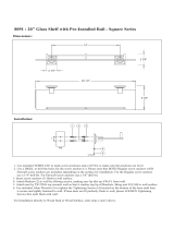
Wall plate (A) can be mounted to two studs that are 16" apart. Use a stud finder to locate the edges of the
studs. Use of an edge-to-edge stud finder is highly recommended. Based on their edges, draw a vertical line
down each stud’s center. Place wall plate on wall as a template. The top mounting slots should be located .36"
above the desired screen center for PLA 60 and PLA 60-S and .43" below the desired screen center for PLAV 60
and PLAV 60-S. Level plate, and mark the center of the eight mounting holes. Make sure that the mounting
holes are on the stud centerlines. Drill eight 7/32" dia. holes 3" deep. Make sure that the wall plate is level,
secure it using eight 5/16 x 3" wood screws (O) and washers (P).
Skip to step 2 on page 6.
A
O
P
• Never mount this product to metal studs without the
required accessory.
WARNING

5 of 9 ISSUED: 05-02-06 SHEET #: 202-9112-3 12-05-06
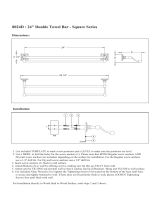
IMPORTANT! Concrete must be 2000 psi density
minimum.
Use wall plate (A), making sure that it is level, as a
template to mark holes. The top mounting slots should
be located .36" above the desired screen center for PLA
60 and PLA 60-S and .43" below the desired screen
center for PLAV 60 and PLAV 60-S. Use the masonry bit
to drill 5/16" (8 mm) dia. holes to a minimum depth of 3"
(76 mm). Insert anchors in holes flush with wall as shown
(right). Place wall plate (A) over anchors (W) and secure
with 5/16 x 3" wood screws (O) and washers (P).
• Concrete must be 2000 psi density minimum. Lighter density concrete may not hold concrete anchor.
• Make sure that the supporting surface will safely support the combined load of the equipment and all attached
hardware and components.
• Never exceed the Maximum UL Load Capacity of 175 lb (79 kg).
• Never mount this product to metal studs.
WARNING
• Always attach concrete expansion anchors directly to
load-bearing concrete.
• Never attach concrete expansion anchors to concrete
covered with plaster, drywall, or other finishing mate-
rial. If mounting to concrete surfaces covered with a
finishing surface is unavoidable, the finishing surface
must be counterbored as shown below. If plaster/
drywall is thicker than 5/8", custom fasteners must be
supplied by installer (Not evaluated by UL).
WARNING
• Tighten wood screws so that wall plate is firmly
attached, but do not overtighten. Overtightening can
damage screws, greatly reducing their holding power.
• Never tighten in excess of 80 in • lb (9 N.M.).
WARNING
1
Installation to Concrete Wall
A
O
P
W
concrete
surface
1
3
2
Drill hole(s) and insert anchor(s) (W)
mounting
plate
Place plate over anchor(s) (W) and secure with screw(s)(O)
Tighten all fasteners
W
W
CUTAWAY VIEW
INCORRECT
CORRECT
mounting
plate
plaster/
dry wall
concrete
mounting
plate
concrete
plaster/
dry wall

6 of 9
ISSUED: 05-02-06 SHEET #: 202-9112-2 06-21-06
Snap four cable management clips (R) into top or bottom of arm assembly (C) as shown. Cable ties (S) are used
with clips for cord management.
Slide one mesh sleeve (T) over each cable. Use cable ties (S) to tighten mesh sleeves to cables.
R
S
C
3
T
3-1
K
D
N
J
D
M
J
C
DETAIL 3
A
Note: There are five mounting positions. The
center position is shown (right). Slide washer (J)
over wall support arm axle (D). Next, insert plastic
cap (N) into axle. Then, insert holding pin (M) into
axle. See detail 1.
Note: Fit of axle (D) into wall plate (A) and arm
assembly (C) will be tight. Gently tap into place
with a hammer if necessary.
2
2-1
Insert socket cap screw (K) into hole at bottom of
wall support arm axle (D) as shown in detail 3.
Tighten screw using 9/64" allen wrench (Q).
Place arm assembly (C) with washer (J) into wall
plate (A). Insert axle assembly shown in detail 1
through wall plate (A), arm assembly (C), and
washer (J). Lock axle in place by aligning holding
pin (M) with notches shown in detail 2.
2-2
DETAIL 1
NOTCH
DETAIL 2
• If you are uncertain that product is properly installed, call customer care.
WARNING

7 of 9 ISSUED: 05-02-06 SHEET #: 202-9112-3 12-05-06
B
I
F
GENERIC
ADAPTER BRACKET
Insert and tape carriage bolt (I) into top hole of pitch-roll assembly (B). Attach tilt-roll assembly to adapter
bracket with four M10 socket screws (F). Tighten screws using 6 mm allen wrench (U).
Note: Adapter bracket (not UL evaluated, sold separately) will vary in size and style.
Note: Refer to adapter bracket instruction sheet for attachment of adapter bracket to plasma before proceeding
with step 5. If your adapter bracket has an aluminum race attached to it, remove before proceeding and discard race. It is
not used with this product.
• Do not overtighten screws! Overtightening may hinder
roll option.
CAUTION
4
5
Attach two pieces of vinyl trim (E) to wall plate (A). Next, attach one piece of vinyl trim to bottom of swivel box on arm
assembly (C).
4-1
Insert one finishing cap (L) into each unused hole of wall plate (A).
L
A
E
SWIVEL BOX
C

8 of 9
ISSUED: 05-02-06 SHEET #: 202-9112-2 06-21-06
Insert two M10 screws (F) into swivel box on arm assembly (C) as shown. Leave approx. 1/4" of exposed
thread.
.25"
F
• Use an assistant or mechanical lifting equipment to safely lift and position the plasma TV.
WARNING
• After tilt is adjusted, all fasteners must be tightened.
Failure to do so will result in damage to the mount.
CAUTION
6
6-1
6-2
fig 6.1 fig 6.2
SWIVEL BOX
Hook tilt-roll assembly (B) onto M10 screws (F).
Insert carriage bolt (I) into slot of swivel box as
shown in figure 6.1. Install nylon washer (G) and tilt
adjustment knob (H).
Install remaining two M10 screws (F) as shown in
figure 6.2. HAND TIGHTEN all four M10 screws to
allow for tilt adjustment. Remove tape from carriage
bolt (I). For tilt adjustment, push back on the top of
plasma to relieve pressure on knob. Adjust tilt to
desired position and tighten tilt adjustment knob (H),
then securely tighten all four M10 screws (F) using 6
mm allen wrench (U).
I
B
F
H
G
SWIVEL BOX
H
F
I
C

9 of 9 ISSUED: 05-02-06 SHEET #: 202-9112-3 12-05-06
FOR PLAV 60 ONLY:
7
7-1
ARTICULATING ARM
PLASMA
8
Depending on the specific size & weight of the plasma,
articulating swing arm may be angled at different
positions, causing plasma to appear to lean sideways
at different articulating positions. Tilt-roll assembly (B)
allows plasma to be manually adjusted, so plasma can
be horizontal at all positions. To adjust, gently rotate
plasma by hand to desired position.
SOCKET
SCREW
Position of screen may be adjusted vertically up to
.79" in each direction by doing the following:
• To lower screen, turn socket screw shown in figure
8.1 clockwise with 10 mm allen wrench (V).
• To raise screen, turn socket screw shown in figure
8.1 counterclockwise with 10 mm allen wrench (V).
fig 8.1
If it is too difficult to adjust roll of plasma, loosen
screws shown in figure 7.1 using a phillips screw-
driver.
IMPORTANT! Do not loosen or tighten screws
more than 1/8 turn.
ROLL
ADJUSTMENT
SCREWS
fig 7.1
©2006 Peerless Industries, Inc. All rights reserved.
Peerless is a registered trademark of Peerless Industries, Inc.
All other brand and product names are trademarks or registered trademarks of their respective owners.
/