
R
ECOMMENDED ADHESIVES: Armstrong
®
P
roConnect™ Professional Hardwood
Flooring Adhesive, Armstrong 57 Urethane Adhesive or Armstrong EverLAST™
Premium Urethane Adhesive
R
ECOMMENDED ADHESIVE REMOVER: Armstrong Adhesive Cleaner
RECOMMENDED CLEANER: Armstrong Hardwood & Laminate Floor Cleaner
RECOMMENDED UNDERLAYMENT (Floating installation system only):
P
olyFoam Underlayment, Armstrong Quiet Comfort™ or Armstrong Quiet
Comfort Premium Underlayment
RECOMMENDED WOOD GLUE (Floating installation and joint gluing): Armstrong
9
9™ Hardwood & Laminate Flooring Adhesive
ADHÉSIFS RECOMMANDÉS : Adhésif Professionnel pour revétement de plancher
d
e bois franc Armstrong
®
P
roConnect™, adhésif à l’uréthane Armstrong 57 ou
Adhésif à l’uréthane de qualité supérieure Armstrong EverLAST™
DISSOLVANT D’ADHÉSIF RECOMMANDÉ : dissolvant d’adhésif Armstrong
N
ETTOYANTS RECOMMANDÉS : nettoyant de parquets en bois franc et laminés
Armstrong
SOUS-COUCHE RECOMMANDÉE (système de pose flottante seulement) : Sous-
c
ouche PolyFoam, Sous-couche Armstrong Quiet Comfort™ ou Armstrong Quiet
Comfort de première qualité
COLLE À BOIS RECOMMANDÉE (pose flottante et jointures collées) : adhésif de
p
lancher de bois franc et laminé Armstrong 99™
ADHESIVOS RECOMENDADOS: Adhesivo profesional Armstrong
®
ProConnect™
para pisos de madera dura, adhesivo de uretano Armstrong 57, o Adhesivo de
uretano Armstrong EverLAST™ de primera calidad
QUITA-ADHESIVO RECOMENDADO: limpiador para adhesivo Armstrong
LIMPIADOR RECOMENDADO: Limpiador para pisos de madera dura y
laminados Armstrong
CONTRAPISO RECOMENDADO (Sistema de instalación flotante solamente):
PolyFoam Underlayment (contrapiso), Bases de piso de primera Armstrong
Quiet Comfort™ o Armstrong Quiet Comfort
PEGAMENTO PARA MADERA RECOMENDADO (Instalación flotante y encolado
de juntas): Adhesivo de pisos de madera dura y laminados Armstrong 99™
ATTENTION INSTALLERS
IMPORTANT HEALTH NOTICE FOR MINNESOTA RESIDENTS ONLY:
THESE BUILDING MATERIALS EMIT FORMALDEHYDE. EYE, NOSE, AND THROAT IRRITATION, HEADACHE, NAUSEA
AND A VARIETY OF ASTHMA-LIKE SYMPTOMS, INCLUDING SHORTNESS OF BREATH, HAVE BEEN REPORTED AS A
RESULT OF FORMALDEHYDE EXPOSURE. ELDERLY PERSONS AND YOUNG CHILDREN, AS WELL AS ANYONE WITH
A HISTORY OF ASTHMA, ALLERGIES,OR LUNG PROBLEMS, MAY BE AT GREATER RISK. RESEARCH IS CONTINUING
ON THE POSSIBLE LONG-TERM EFFECTS OF EXPOSURE TO FORMALDEHYDE.
REDUCED VENTILATION MAY ALLOW FORMALDEHYDE AND OTHER CONTAMINANTS TO ACCUMULATE IN THE
INDOOR AIR. HIGH INDOOR TEMPERATURES AND HUMIDITY RAISE FORMALDEHYDE LEVELS. WHEN A HOME IS
TO BE LOCATEDIN AREAS SUBJECT TO EXTREME SUMMER TEMPERATURES,AN AIR-CONDITIONING SYSTEM CAN
BE USED TO CONTROL INDOOR TEMPERATURE LEVELS. OTHER MEANS OF CONTROLLED MECHANICAL
VENTILATION CAN BE USED TO REDUCE LEVELS OF FORMALDEHYDE AND OTHER INDOOR AIR CONTAMINANTS.
IF YOU HAVE ANY QUESTIONS REGARDING THE HEALTH EFFECTS OF FORMALDEHYDE, CONSULT YOUR DOCTOR
OR LOCAL HEALTH DEPARTMENT.
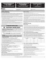
Sawing, sanding and machining wood products can produce wood dust. Airborne wood dust can cause
respiratory, eye and skin irritation. The International Agency for Research on Cancer (IARC) has
classified wood dust as a nasal carcinogen in humans.
Precautionary Measures: If power tools are used, they should be equipped with a dust collector. If high dust levels
are encountered, use an appropriate NIOSH-designated dust mask. Avoid dust contact with eye and skin.
First Aid Measures in Case of Irritation: In case of irritation, flush eyes or skin with water for at least 15 minutes.
If you have any technical or installation questions, or to request a Material Safety Data Sheet, please call
1 800 233 3823
or visit www.floorexpert.com, our technical website.
CAUTION: WOOD DUST
I. GENERAL INFORMATION
Owner/Installer Responsibility
Beautiful hardwood floors are a product of nature and therefore, not perfect. Our hardwood floors are manufactured in accordance
with accepted industry standards, which permit grading deficiencies not to exceed 5%. These grading deficiencies may be of a
manufacturing or natural type. When flooring is ordered, 5% must be added to the actual square footage needed for cutting and
grading allowance (10% for diagonal installations).
• The owner/installer assumes all responsibility for final inspection of product quality. Inspection of all flooring should be done prior
to installation. Carefully examine flooring for color, finish and quality before installing it. If material is not acceptable, do not install
it and contact the seller immediately.
• Prior to installation of any hardwood flooring product, the owner/installer must determine that the job-site environment and the
sub-surfaces involved meet or exceed all applicable standards. Recommendations of the construction and materials industries, as
well as local codes, must be followed. These instructions recommend that the construction and subfloor be clean, dry, stiff,
structurally sound and flat. The manufacturer declines any responsibility for job failure resulting from, or associated with, subfloor
and substrates or job-site environmental deficiencies.
• Prior to installation, the owner/installer has final inspection responsibility as to grade, manufacture and factory finish. The installer
must use reasonable selectivity and hold out or cut off pieces with deficiencies, whatever the cause. Should an individual piece be
doubtful as to grade, manufacture or factory finish, the installer should not use the piece.
• Use of stain, filler or putty stick for touch-up and appropriate products for correcting subfloor voids is accepted as part of normal
installation procedures.
INSTALLATION INSTRUCTIONS
1/4″, 5/16″, 3/8″ & 1/2″
(6 mm, 8 mm, 10 mm y 13 mm)
ENGINEERED PRODUCTS
FOR STAPLE-DOWN, MECHANICALLY FASTENED,
FLOATING AND GLUE-DOWN APPLICATIONS.
D
O NOT FLOAT 1/4
″ P
RODUCTS.
M
ODE D’INSTALLATION
D
E 6 mm, 8 mm,10 mm et 13 mm
(
1/4 po, 5/16 po, 3/8 po et 1/2 po)
P
RODUITS HAUTE PERFORMANCE
POUR POSES AVEC AGRAFES, ATTACHES MÉCANIQUE,
FLOTTANT ET À COLLER. NE PAS POSER DE PRODUITS
DE 1/4 PO SOUS FORME DE PLANCHER FLOTTANT.
INSTRUCCIONES DE INSTALACIÓN
1/4″, 5/16″, 3/8″ y 1/2″
(6 mm, 8 mm, 10 mm y 13 mm)
P
RODUCTOS DE INGENIERÍA
PARA USOS ENCLAVADOS, DE FIJACIÓN MECÁNICA,
F
LOTANTES Y ENCOLADOS. NO INSTALE PRODUCTOS
DE 1/4″ POR EL MÉTODO DE FLOTACIÓN.
For complete warranty information call 1 800 233 3823 or visit www.armstrong.com.
II. PREPARATION
Storage and Handling
Handle and unload with care. Store in a dry place, being sure to provide at least a four-inch air space under cartons which are stored
upon “on-grade” concrete floors. Flooring should not be delivered until the building has been enclosed with windows, doors are in place,
and cement work, plastering and all other “wet” work is completed and dry.
Although it is not necessary to acclimate engineered flooring, it is best to store it in the environment in which it is expected to perform
prior to installation. Check adhesive label for adhesive storage limitations.
Job-Site Conditions
• The building should be enclosed with all outside doors and windows in place. All concrete,
masonry, framing members, drywall, paint and other “wet” work should be thoroughly
dry. The wall coverings should be in place and the painting completed, except for the final
coat on the base molding. When possible, delay installation of base molding until flooring
installation is complete. Basements and crawl spaces must be dry and well ventilated.
• Exterior grading should be complete with surface drainage, offering a minimum drop of
3″ in 10′ (7.6 cm in 3.05 m) to direct flow of water away from the structure. All gutters
and downspouts should be in place.
• Engineered flooring may be installed below-, on- or above-grade level. Do not install in full
bathrooms.
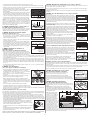
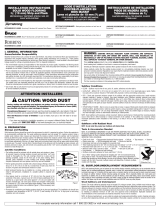
• Crawl spaces must be a minimum of 18″ (46 cm) from the ground to the underside of the
joists. A ground cover of 6–20 mil black polyethylene film is essential as a vapor barrier
with joints lapped 6″ (15 cm) and sealed with moisture-resistant tape. The crawl space
should have perimeter venting equal to a minimum of 1.5% of the crawl space square
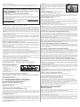
footage. These vents should be properly located to foster cross ventilation (Figure 1).
Figure 1
2nd Floor
(above ground level)
1st Floor
(ground level)
Basement
(below ground level)
Soil Line
RECOMMENDED ADHESIVES: Armstrong ProConnect Professional Hardwood
Flooring Adhesive, Bruce
®
Equalizer™ Urethane Adhesive or Armstrong EverLAST
P
remium Urethane Adhesive
RECOMMENDED ADHESIVE REMOVER: Bruce Adhesive Cleaner
RECOMMENDED CLEANER: Bruce Hardwood & Laminate Floor Cleaner,
A
rmstrong Hardwood & Laminate Floor Cleaner
RECOMMENDED UNDERLAYMENT (Floating installation system only): Bruce
ComfortGuard™, Armstrong Quiet Comfort or Armstrong Quiet Comfort
P
remium Underlayment
RECOMMENDED WOOD GLUE (Floating installation and joint gluing): Bruce
EverSeal™ Adhesive
ADHÉSIFS RECOMMANDÉS : Adhésif Professionnel pour revétement de plancher
de bois franc Armstrong ProConnect, adhésif à l’uréthane Bruce
®
Equalizer™ ou
A
dhésif à l’uréthane de qualité supérieure Armstrong EverLAST
DISSOLVANT D’ADHÉSIF RECOMMANDÉ : dissolvant d’adhésif Bruce
NETTOYANTS RECOMMANDÉS : nettoyant pour planchers en bois franc et
l
aminé Bruce
®
,
nettoyant pour planchers en bois franc et laminé Armstrong
SOUS-COUCHE RECOMMANDÉE (système de pose flottante seulement): Bruce
ComfortGuard™, Sous-couche Armstrong Quiet Comfort ou Armstrong Quiet
C
omfort de première qualité
COLLE À BOIS RECOMMANDÉE (pose flottante et jointures collées): adhésif
Bruce EverSeal™
ADHESIVOS RECOMENDADOS: Adhesivo profesional Armstrong ProConnect
para pisos de madera dura, adhesivo de uretano Bruce
®
Equalizer™ o Adhesivo
d
e uretano Armstrong EverLAST de primera calidad
Q
UITA-ADHESIVO RECOMENDADO: Limpiador para adhesivo Bruce
L
IMPIADOR RECOMENDADO: Limpiador para pisos de madera dura y
l
aminados Bruce, Limpiador para pisos de madera dura y laminados Armstrong
C
ONTRAPISO RECOMENDADO (Sistema de instalación flotante solamente): Bruce
C
omfortGuard™ , Bases de piso de primera Armstrong Quiet Comfort o
A
rmstrong Quiet Comfort
P
EGAMENTO PARA MADERA RECOMENDADO (Instalación flotante y encolado
d
e juntas): Bruce EverSeal™ Adhesive
R
ECOMMENDED ADHESIVES: Armstrong ProConnect Professional Hardwood
Flooring Adhesive, FusionLock™ Urethane Adhesive or Armstrong EverLAST
Premium Urethane Adhesive
R
ECOMMENDED ADHESIVE REMOVER: Robbins
®
A
dhesive Cleaner
RECOMMENDED CLEANER: Armstrong Hardwood & Laminate Floor Cleaner
RECOMMENDED UNDERLAYMENT (Floating installation system only): PolyCushion
Underlayment, Armstrong Quiet Comfort or Armstrong Quiet Comfort Premium
Underlayment
RECOMMENDED WOOD GLUE (Floating installation and joint gluing): Armstrong
99 Hardwood & Laminate Flooring Adhesive
A
DHÉSIFS RECOMMANDÉS : Adhésif Professionnel pour revétement de plancher
de bois franc Armstrong ProConnect, adhésif à l’uréthane FusionLock™ ou
Adhésif à l’uréthane de qualité supérieure Armstrong EverLAST
D
ISSOLVANT D’ADHÉSIF RECOMMANDÉ : dissolvant d’adhésif Robbins
®
NETTOYANTS RECOMMANDÉS : Nettoyant de parquets en bois franc et laminés
Armstrong
SOUS-COUCHE RECOMMANDÉE (système de pose flottante seulement): Sous-
couche PolyCushion, Sous-couche Armstrong Quiet Comfort ou Armstrong Quiet
Comfort de première qualité
COLLE À BOIS RECOMMANDÉE (pose flottante et jointures collées): Adhésif de
plancher de bois franc et laminé Armstrong 99
ADHESIVOS RECOMENDADOS: Adhesivo profesional Armstrong ProConnect
para pisos de madera dura, adhesivo de uretano FusionLock™, o Adhesivo de
uretano Armstrong EverLAST de primera calidad
QUITA-ADHESIVO RECOMENDADO: Limpiador para adhesivo Robbins
®
LIMPIADOR RECOMENDADO: Limpiador para pisos de madera dura y
laminados Armstrong
CONTRAPISO RECOMENDADO (Sistema de instalación flotante solamente):
PolyCushion Underlayment (contrapiso), Bases de piso de primera Armstrong Quiet
Comfort™ o Armstrong Quiet Comfort
PEGAMENTO PARA MADERA RECOMENDADO (Instalación flotante y encolado
de juntas): Adhesivo de pisos de madera dura y laminados Armstrong 99
Do not staple down products that exceed 5
″
″
in width or Pecan™ or Maple products.
Do not staple down 5/16
″
″
products.
Glue down or float only.
N
e pas agrafer des produits d’une largeur supérieure à 5 po ni les produits en
Pecan™ ou en Érable. Les produits de 5/16 po ne doivent pas être cloués;
il faut soit les coller soit adopter la méthode de la pose du plancher flottant.
No enclave productos con un ancho mayor que 5″ o Productos de
Pecan™ y Arce. No enclave productos 5/16
″. Encolado o flote
s
olamente.
D
o not staple down products that exceed 5
″ i
n width
or Pecan, Maple, WearMaster
®
, Newcastle™,
Northshore
®
, Hillden™ or Hickory products. Do not use
fl
oating system for Balance™ Strip or any
self-adhesive products.
N
e pas agrafer des produits d’une largeur supérieure à 5 po ni les
produits en hickory, érable, Pecan ou les WearMaster
®
, Newcastle™,
Northshore
®
et Hillden™. Ne pas utiliser de système flottant pour les
l
ames Balance™ Strip ni tout produit auto-adhésif.
No enclave productos con un ancho mayor que 5″ o productos de
P
ecan, Arce, WearMaster
®
,
Newcastle™, Northshore
®
,
Hillden™ o
Hickory. No use el sistema de flotación para la Balance™ Strip o para
ningún producto autoadhesivo.
Do not staple down products that exceed 5
″
″
in width or Pecan or Maple products.
Ne pas agrafer des produits d’une largeur supérieure à 5 po ni
l
es produits en Pecan ou en Érable.
No enclave productos con un ancho mayor que 5″ o productos
de Pecan y Arce.

•
Polyfilm Test: Apply 3′×3′ (1 m × 1 m) pieces of polyethylene film to the subfloor
and leave in place for 24 hours. Assure all edges are completely sealed with water-
resistant tape. Darkened concrete or condensation on film indicates presence of
m
oisture and requires additional measurements with the Tramex Meter, Calcium
Chloride or RH test.
NOTE: The following tests are required in commercial applications. Either or both tests
a
re acceptable.
• Calcium Chloride Test (ASTM F 1869): The maximum moisture transfer must not
e
xceed 3 lbs./1000 ft.
2
i
n 24 hrs. with this test.
• RH Levels in Concrete Using In-situ Probes (ASTM F 2170-02) should not exceed 75%.
“DRY” CONCRETE AS DEFINED BY THESE TESTS CAN BE WET AT OTHER TIMES OF THE YEAR. THESE TESTS DO NOT
GUARANTEE A DRY SLAB. ALL NEW CONSTRUCTION CONCRETE SLABS SHOULD HAVE A MINIMUM OF 10 MIL POLY FILM
M
OISTURE BARRIER BETWEEN THE GROUND AND THE CONCRETE.
Moisture Retardant Systems
If excessive moisture is present or anticipated, use Armstrong VapArrest S-135 Professional Moisture Retardant System or
inexpensive sheet vinyl to reduce vapor intrusion.
NOTE: DO NOT use Armstrong ProConnect™ Professional Hardwood Flooring Adhesive when using Armstrong VapArrest S-135
Professional Moisture Retardant System or sheet vinyl as a moisture retardant. Use only Bruce Equalizer™, Armstrong 57 , Robbins
®
F
usionLock™ or Armstrong EverLAST™ Premium Urethane Adhesive.
• Armstrong VapArrest S-135: Apply the materials after all subfloor preparation is complete. Follow the instructions on the VapArrest
S
-135 label. Allow 8 –24 hours curing time before application of the hardwood flooring.
• Sheet vinyl: An inexpensive sheet vinyl or “slip-sheet” (felt-backed with vinyl wear layer) may be installed. Use a premium grade,
a
lkali-resistant adhesive and a full-spread application system to properly bond the vinyl to the subfloor. Follow the sheet vinyl
manufacturer’s instructions for installation procedures. A bond test may be required as an adhesion test. Install several small areas
(3′ x 3′) (1 m x 1 m) and allow the vinyl to set for 72 hours. Remove the vinyl. If the backing remains attached to the concrete, the
subfloor should be acceptable for sheet vinyl installation. Install the sheet vinyl and allow the adhesive to cure for 24 hours prior
t
o beginning installation. Degloss as necessary to create an adequate adhesive bond. Always check for adequate adhesive bond.
Acoustic Concrete (Glue-Down or Floating Installations Only)
Acoustic concrete normally contains large quantities of gypsum that may inhibit the adhesive’s capability to properly bond. Acoustic
concrete must be primed with the concrete manufacturer’s recommended primer/surface hardener. Test the concrete by scraping the
s
urface with a nail or other sharp object. If the concrete powders or crumbles, it is not sound and suitable for direct application of
hardwood flooring and may require the use of a floating sub-floor system. Always check for adequate adhesive bond. The concrete
must have a minimum compressive strength of 2000 PSI.
C
eramic, Terrazzo, Slate & Marble (Glue-Down or Floating Only)
A
ll grout joints and broken corners that exceed 3/16″ (5 mm) must be filled with a cementitious leveling compound such as
Armstrong S-194 Patch, Underlayment & Embossing Leveler with S-195 Underlayment Additive. The surface should be cleaned and
abraded to create a good bonding surface for the adhesive. Loose tiles must be re-adhered to the subfloor or filled as above. Remove
a
ll sealers and surface treatments. Always check for adequate adhesive bond.
A
coustic Cork Underlayment (Glue-Down or Floating Only)
The flooring can be glued or floated directly over full-spread, permanently bonded acoustic cork. The cork should have a density of
no less than 11.4 lb./cubic foot. The cork, in general, should be pure cork combined with a polyurethane or resin binder. Install cork
i
n accordance with cork manufacturer’s recommendations. Always check for adequate adhesive bond. When floating floors over cork
DO NOT use foam underlayment.
Wood Subfloors and Underlayment (All Installation Methods)
G
eneral: The wood subflooring materials must not exceed 13% moisture content. Using a realiable wood moisture meter, measure
moisture content of both the subfloor and the hardwood flooring to determine proper moisture content. The difference between the
moisture content of the wood subfloor and the hardwood flooring must not exceed 4%. When installing parallel to the floor joists it
m
ay be necessary to stiffen the subfloor system by installing an additional minimum of 3/8″ (9.5 mm) approved underlayment.
Applicable standards and recommendations of the construction and materials industries must be met or exceeded.
NOTE: As flooring manufacturers, we are unable to evaluate each engineered system. Spacing and spans, as well as their engineering
methods, are the responsibility of the builder, engineer, architect or consumer, who is better able to evaluate the expected result based
on site-related conditions and performance. The general information provided below describes common, non-engineered
joist/subfloor systems. Engineered flooring systems may allow for wider joist spacing and thinner subflooring materials.
Wood Structural Panel Subfloors and Underlayment (All Installation Methods)
Structural panels/underlayment must be installed sealed side down. When used as a subfloor allow 1/8″ (3 mm) expansion space
between each panel. If spacing is inadequate, cut in with a circular saw. Do not cut in expansion space on tongue and groove panels.
• Plywood: Must be minimum CDX grade (exposure 1) and meet US Voluntary Product Standard PS1 performance standard or
Canadian performance standard CAN/CSA 0325-0-92. The preferred thickness is 3/4″ (19 mm) as a subfloor [minimum 5/8″
(16 mm)] or 3/8″ (9.5 mm) as underlayment.
• Oriented Strand Board (OSB): Conforming to US Voluntary Product Standard PS2 or Canadian performance standard CAN/CSA
0325-0-92 construction sheathing. Check underside of panel for codes. When used as a subfloor, the panels must be tongue and
groove and installed sealed side down. Minimum thickness to be 23/32″ (18 mm) thick when used as a subfloor or 3/8″ (9.5 mm)
as underlayment.
• Waferboard and Chipboard: Conforming to US Voluntary Product Standard PS2 or Canadian performance standard CAN/CSA
0325-0-92. Must be 3/4″ (19 mm) thick when used as a subfloor and 3/8″ (9.5 mm) thick when used as an underlayment.
• Particleboard: Must be a minimum 40-lb. density, stamped underlayment grade and 3/4″ (19 mm) thick.
Solid Wood Subfloors (All Installation Methods)
• Minimum 3/4″ (19 mm) thick with a maximum width of 6″ (15 cm) installed at a 45˚ angle to the floor joists.
• Group 1 dense softwood (Pine, Larch, Douglas Fir, etc.) No. 2 common, kiln dried with all board ends bearing on joists.
• For glue-down applications add 3/8″ (9.5 mm) approved underlayment.
Existing Wood Flooring (All Installation Methods)
• Existing engineered flooring must be well bonded/fastened. When gluing over existing wood flooring of any thickness, the
finishing materials must be abraded or removed to foster an adequate adhesive bond. When flooring is to be mechanically
fastened, the existing engineered wood flooring must be a minimum of 3/8″ (9.5 mm) thick installed over approved wood/wood
composite underlayment that has been properly fastened. When installing over engineered flooring that is glued to concrete, the
minimum thickness of that flooring must be 1/2″ (13 mm) to allow for the length of the fastener.
• Existing solid wood flooring that exceeds 6″ (15 mm) in width must be covered with 3/8″ (9.5 mm) approved underlayment and
fastened as required. Do not install over solid flooring attached directly to the concrete.
Vinyl, Resilient Tile, Cork Flooring and Linoleum
(All Installation Methods, see notes below)
(Glue-Down Installations)
DO NOT use Armstrong ProConnect Professional Hardwood Flooring Adhesive when installing over these surfaces. Use only Bruce
Equalizer, Armstrong 57, Robbins FusionLock or Armstrong EverLAST Premium Urethane Adhesive.
• Make sure the floor covering materials are well bonded to the subfloor/underlayment with full-spread adhesive and are no more
than two layers thick, not to exceed 3/16″ (5 mm).
• With approved wood/wood composite subfloors, if vinyl or tiles are loose, broken, or in poor condition, install a 3/8″ (9.5 mm)
approved underlayment directly over the flooring materials.
• Clean the flooring materials as necessary to create a good adhesive bond. If a maintenance material is present on the floor covering
or a gloss is present, de-gloss with a flooring pad and a commercially available stripper, then rinse completely. Allow ample drying
time. (NOTE: Do not sand any resilient products. They may contain asbestos fibers, which may be harmful.)
• Cork floors must have all sealers and surface treatments removed before installation begins. Always check for adequate adhesive bond.
2
Tools & Accessories Needed (All Installation Methods)
• Broom • Tape measure • Hammer • Chalk line & chalk • Hand saw or jamb saw
• Recommended hardwood flooring cleaner • Electric power saw • Eye protection • Recommended wood glue
• Moisture Meter (wood, concrete or both) • Transition and wall moldings • NIOSH-designated dust mask
(Add for Glue-Down Installations)
• Recommended adhesive and adhesive remover
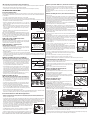
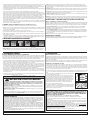
• 1/4″×1/2″×3/16″ (6 mm × 13 mm × 5 mm) V-Notch
trowel (Figure 2)
• 3M Scotch-Blue™ 2080 tape
• Recommended wood glue for floors exceeding 3-1/4″
(9.5 cm) in width
• Armstrong VapArrest™ S-135 Professional Moisture Retardant System on concrete (if needed).
Use with urethane adhesive only.
(Add for Mechanically Fastened/Staple-Down Installations)
• Stanley-Bostitch “FloorRunner”, Senco SLS20HF or equivalent • 1″ Staples/fasteners (minimum) • Compressor and hose
• Nylon/Plastic tapping block • In-line regulator • Recommended wood glue for floors exceeding 3-1/4″ (9.5 cm) in width
(Add for Floating Installations)
• Recommended underlayment • Pull bar • Tapping block • Recommended wood glue
III. SUBFLOOR/UNDERLAYMENT REQUIREMENTS
Recommended Subfloor/Underlayment Surfaces
(Glue Down and Floating Installations Only)
• Concrete • Ceramic Tile, Terrazzo, Slate & Marble • Acoustic cork
(All Installation Methods)
• Wood subfloors • Wood structural panels and underlayment • Fully adhered existing wood floors
• Fully adhered vinyl sheet, resilient tile, cork flooring and linoleum
Concrete (Glue-Down and Floating Installations Only)
The flooring can be glued directly to concrete with a minimum compressive strength of 3000 PSI. Do not install over a concrete
sealer or painted concrete. If present, remove by grinding or sanding. Do not install over slick, heavily troweled or burnished
concrete. Roughen the surface as necessary by sanding or grinding. Use an appropriate NIOSH-designated dust mask. Floating floors
can be installed over any structurally sound concrete.
Concrete Moisture Tests
All concrete subfloors should be tested, and results documented, for moisture content. Visual checks may not be reliable. Test several
areas, especially near exterior walls and walls containing plumbing. Acceptable test methods for subfloor moisture content include:
• A 3% Phenolphthalein in Anhydrous Alcohol Solution: Chip the concrete at least 1/4″ (6 mm) deep (do not apply directly to the
concrete surface) and apply several drops of the solution to the chipped area. If any color change occurs, further testing is required.
• Tramex Concrete Moisture Encounter Meter (Figure 3): Moisture readings should not exceed 4.5 on the upper scale. (Figure 3 shows
an unacceptable reading of over 4.5.)
Figure 2
F
igure 3
S
ubfloors with Radiant Heat
(
Not acceptable for 5/16
″ E
ngineered Installations)
NOTE: Always make certain the product selected is recommended for this type application. The following products are not
recommended to be installed over radiant heat subfloors: Armstrong
®
Global Exotics™, Bruce
®
Kempas Plank, Merbau™ Plank,
N
ewcastle™ Plank, Coastal Woodlands
®
.
• System must be operational and heated for at least 7 days prior to beginning the installation.
•
Use an incremental control strategy that brings the floor through temperature changes gradually, which may include an external thermostat.
• Turn off heat and let subfloor cool down to room temperature 3 –4 hours prior to starting the job.
•
BEFORE installation begins, ascertain that the heating system is designed and controlled for wood flooring and that the circuit does
not include other floor covering types. Failure to do so may cause excessive heat damage and shrinkage. NOTE: Refer to radiant
heat system manufacturer’s precautions for staple-down installation. Beware of stapling through radiant tubing or mesh.
•
After installation, turn the heating system back on immediately. The finished floor surface must not exceed 85°F (29°C) throughout
the life of the floor.
• Radiant heating systems normally create dry heat that can lower interior humidity levels. It may be necessary to add humidity with
humidifiers to maintain the recommended levels (35–55%) and prevent damage to the wood floor.
• The flooring should be end-glued over radiant heat to reduce longitudinal shrinkage. Apply a bead of the recommended wood glue
to the groove end, then insert the tongue. Wipe excess adhesive away immediately.
W
ARNING:
EXISTING IN-PLACE RESILIENT FLOOR COVERING AND ASPHALTIC ADHESIVES.
DO NOT SAND, DRY SWEEP, DRY SCRAPE, DRILL, SAW, BEADBLAST, OR MECHANICALLY CHIP OR
P
ULVERIZE EXISTING RESILIENT FLOORING, BACKING, LINING FELT, ASPHALTIC “CUTBACK”
ADHESIVE, OR OTHER ADHESIVE.
T
hese existing in-place products may contain asbestos fibers and/or crystalline silica.
Avoid creating dust. Inhalation of such dust is a cancer and respiratory tract hazard.
Smoking by individuals exposed to asbestos fibers greatly increases the risk of serious bodily harm.
Unless positively certain that the existing in-place product is a non-asbestos-containing material, you must presume it
contains asbestos. Regulations may require that the material be tested to determine asbestos content and may govern
removal and disposal of material.
See current edition of the Resilient Floor Covering Institute (RFCI) publication Recommended Work Practices for
Removal of Resilient Floor Coverings for instructions on removing all resilient floor covering structures or contact your
r
etailer or Armstrong World Industries, Inc. 1 800 233 3823.
The floor covering or adhesive in this package does NOT contain asbestos.
Subfloor Conditions
• CLEAN—Subfloor must be free of wax, paint, oil, sealers, adhesives and other debris.
• LEVEL/FLAT—Within 3/16″ in 10′ (5 mm in 3 m) and/or 1/8″ in 6′ (3 mm in 2 m). Sand high areas or joints. If the floor is to be
g
lued down, fill low areas with a latex additive cementitious leveling compound of 3,000-PSI minimum compressive strength such
as Armstrong S-194 Patch, Underlayment & Embossing Leveler with S-195 Underlayment Additive. Follow the instructions of the
leveling compound manufacturer but make certain that the leveling compounds are completely DRY before beginning installation.
W
hen mechanically fastening the floor down, flatten low spots with a maximum of 6 layers of 15# builders felt, plywood or shims
(not leveling compounds). Leveling materials must provide a structurally sound subfloor that does not affect the holding power of
the fastener.
• DRY—Check and document moisture content of the subfloor using the appropriate moisture test. Concrete subfloors must be a
minimum of 30 days old before testing begins.
• STRUCTURALLY SOUND—Nail or screw any areas that are loose or squeak. Wood panels should exhibit an adequate fastening
pattern, glued/screwed or nailed as system requires, using an acceptable nailing pattern. Typical: 6″ (15 cm) along bearing edges
and 12″ (31 cm) along intermediate supports. Flatten edge swell as necessary. Replace any water-damaged, swollen or
d
elaminated subflooring or underlayments.
Avoid subfloors with excessive vertical movement. Optimum performance of hardwood floor covering products occurs when there
i
s little horizontal or vertical movement of the subfloor. If the subfloor has excessive vertical movement (deflection) before installation
of the flooring, it is likely it will do so after installation of the flooring is complete.
• Where necessary, local regulations prevail.
•
Permanent air conditioning and heating systems should be in place and operational. The installation site should have a consistent room
temperature of 60 –80°F (16–27°C) and humidity of 35–55% for 14 days prior to and during installation and until occupied.

(
Mechanically Fastened/Staple-Down Installations)
• Do not install over floors that exceed one layer, as the thickness of the flooring materials will prevent an adequate mechanical bond.
•
Make certain that the subflooring materials meet minimum requirements.
• Some tile products may be too brittle for staple penetration. Always test an area for breakage before proceeding.
IV. INSTALLING THE FLOOR
G
eneral Installation Tips
N
OTE: When installing UNFINISHED engineered flooring, allow a minimum of 72 hours adhesive curing time before applying seals,
stains and finishes to unfinished flooring. Test the moisture content of the wood in accordance with the stain/finish manufacturer’s
recommendations.
•
Do not staple or mechanically fasten products that exceed 5″ (13 cm) in width.
• Floor should be installed from several cartons at the same time to ensure good color and shade mixture.
• When possible, preselect and set aside boards that blend best with all horizontally mounted moldings used to assure a uniform
fi
nal appearance. Install these boards adjoining the moldings.
•
Be attentive to staggering the ends of the boards at least 4″–6″ (10–15 cm), when
possible, in adjacent rows (Figure 4). This will help ensure a more favorable overall
appearance of the floor.
•
When installing engineered products of uniform length, begin the rows with starter
boards cut to various lengths. Avoid staggering the rows uniformly to prevent
stair-stepping. Boards cut from the opposite end of the row may be used for the
n
ext starter boards.
• Always allow a minimum 1/4″ (6 mm) expansion around all vertical obstructions.
Allow 1/2″ (13 mm) for floating floors.
N
OTE: (For Glue Down Installation) When installing products wider than 3-1/4″ (8 cm),
apply a bead of recommended wood glue to all of the end grooves prior to installing into
the adhesive. (For Staple Down Installation) When installing products wider than
3
-1/4″ (8 cm) but not to exceed 5″ (13 cm), apply a bead of recommended wood glue
to all of the end grooves prior to stapling down.
STEP 1: Doorway and Wall Preparation
(All Installation Methods)
U
ndercut door casings and jambs. Remove any existing base, shoe mold or doorway
thresholds. These items can be replaced after installation. All door casings and jambs
should be undercut to avoid difficult scribe cuts (Figure 5).
S
TEP 2: Establish a Starting Point
(All Installation Methods)
•
Installation parallel to the longest wall is recommended for best visual effects;
however, the floor should be installed perpendicular to the flooring joists unless the
subfloor has been reinforced to reduce subfloor sagging.
• When possible, always begin the layout or installation from the straightest wall,
generally an outside wall.
•
In at least two places, at least 18″ (46 cm) from the corner, measure out equal distance from the starting wall (Figure 6) and snap
a chalk line. The measurement must be the sum of the width of the flooring plus an additional 3/8″ (9.5 mm) to allow for 1/4″
(6 mm) expansion space and the width of the tongue. Allow 1/2″ (13 mm) expansion when installing floating floors. Continue to
S
tep 3; Staple, Glue or Floating.
STEP 3: Installing First & Second Rows
(Mechanically Fastened/Staple-Down Installations)
• Use the longest, straightest boards available for the first two rows. For random and
alternate width products, use the widest plank for the first row. Align tongue of first
row on chalk line. The groove should be facing the starting wall. Pre-drill 1/2″
(13 mm) from back (groove) edge, 1″–2″ (2.5–5 cm) from each end, and at 6″
(15 cm) intervals when possible (Figure 7). Fasten using 4 or 6d finishing nails or
1″ (2.5 cm) pneumatic finish nails/brads. Countersink the nails.
• Pre-drill and blind-nail at a 45° angle through the tongue of the first row every
1″–2″ (2.5–5 cm) from the ends and spaced in 3″–4″ (7.6–10 cm) intervals.
Countersink nails to ensure flush engagement of groove with the following row(s).
Continue blind nailing using this method with following rows until stapler can be
used. Alternatively use a pneumatic finish nailer and install nails/brads at the same
intervals with a minimum length of 1″ (2.5 cm).
• End-joints of adjacent rows should be staggered a minimum of 4″–6″ (10–15 cm),
when possible, to ensure a more favorable overall appearance (Figure 4).
STEP 4: Installing the Floor
(Mechanically Fastened/Staple-Down Installations)
• Always use the recommended stapler for the specific product being installed (see
“Installation Applications”). Use a minimum 1″ (2.5 cm) staple recommended by
the stapler manufacturer 1″–2″ (2.5–5 cm) from the ends spaced at 3″–4″
(8–10 cm) intervals. Continue to Step 5.
• Set compressor at 70 PSI. If tongue damage occurs, lower air pressure (Figure 8).
• Fasten several sacrificial boards to the floor. At least two boards, stapled side by
side, must be used to indicate proper machine adjustments.
• Check for surface damage, air pressure setting, tongue damage, edge blistering,
etc., before proceeding. Make all adjustments and corrections before installation
begins. Once proper adjustments have been made, remove and destroy the boards.
• Install the remainder of the floor working from several cartons.
• The last 1–2 rows will need to be face-nailed when clearance does not permit blind nailing with a stapler or a brad nailer. Pre-drill
and face-nail or pneumatically nail on the tongue side, following the nailing pattern used for the first row.
General Information for Glue-Down Applications
• Maximum adhesive working times: Urethane adhesive – 60 minutes; Armstrong ProConnect Professional Hardwood Flooring
Adhesive – 60 minutes. When not in use, keep the adhesive container tightly closed to prevent thickening. Thickening will cause
difficulty in spreading the adhesive.
• Open times and curing times of ALL adhesives vary dependent upon subfloor porosity, air movement, humidity and room temperature.
Urethane adhesive has a shortened working time in high humidity environments, whereas the working time for ProConnect and
polymeric resin adhesives will be lengthened. In areas of low humidity, open time will be longer with urethane adhesives and shorter
with ProConnect. Adjust the amount of adhesive spread on the subfloor accordingly. The adhesive should not be applied if subfloor or
room temperature is below 60°F (16°C). WORKING TIME WILL VARY DEPENDING ON JOB SITE CONDITIONS.
• Hold trowel at a minimum 45° angle (Figure 9) firmly against the subfloor to obtain a
40–60 ft.
2
(4–5.5 m
2
) per gallon spread rate. The trowel will leave ridges of adhesive and very
little adhesive between the ridges. This will allow you to still see the chalk lines between the
ridges and provide the recommended spread rate.
• For additional application instructions, follow the recommendations on the adhesive container.
• Proper ventilation within the room must be provided. An electric fan is helpful.
• Rolling is not required, but if desired, do not do so until the adhesive has cured for two hours.
NOTE: DO NOT INSTALL FLOORING USING RUBBER MALLETS. STRIKING THE SURFACE
WITH A RUBBER MALLET MAY “BURN” THE FINISH CAUSING IRREPARABLE DAMAGE.
STEP 3: Spread the Adhesive (
Glue-Down Installations)
• Spread sufficient amounts of the recommended adhesive with the recommended trowel
(
Figure 2) in an area that can be covered in 60 minutes (see adhesive information).
• If necessary, nail a sacrificial row with 1″ (2.5 cm) nails on the dry side of your chalk line to help
hold the first row in place.
N
OTE: Avoid installing on the surface of the flooring. If necessary, distribute weight using a
kneeler board.
STEP 4: Installing the Floor (
Glue-Down Installations)
(Figures 10a–10d)
•
Use the longest, straightest boards available for the first two rows. For random and alternate
width products, use the widest plank for the first row. The first row of planks should be installed
with the edge of the groove lined up on the chalk line. The tongue should be facing the starting
w
all. The first row must be aligned and seated in the adhesive, as all additional rows will be
pushed back to this original row. Remove tongue to allow for expansion space, if necessary,
on the row adjoining the wall. Continue to Step 5.
• When installing products wider than 3-1/4″ (8 cm), apply a bead of recommended wood glue
t
o all of the end grooves prior to installing into the adhesive.
• When installing pieces, engage the end-joint first, as close to the side (long) tongue and
groove as possible, then slide together tightly to engage the side (long) joint tongue and
g
roove. To avoid adhesive bleed-through and memory pull-back, avoid sliding pieces through
the adhesive as much as possible when placing them in position.
• During the installation occasionally remove a piece of flooring from the subfloor and inspect
t
he back for proper adhesive transfer. Adequate adhesive transfer is necessary to ensure
sufficient holding strength.
• If the adhesive skins over and fails to transfer, remove and spread new adhesive to achieve
p
roper bonding.
NOTE: Clean adhesive from the surface of the floor frequently, using the recommended adhesive
cleaner. Urethane adhesives become extremely difficult to remove when cured. Do not use 3M
S
cotch-Blue™ 2080 Tape before adhesive is removed from the surface. Use clean towels,
changed frequently, to prevent haze and adhesive residue.
• Check for a tight fit between all edges and ends of each plank. End-joints of adjacent rows
should be staggered 4″–6″ (10–15 cm), when possible, to ensure a more favorable overall
appearance (Figure 4).
•
It may be necessary to align the product with a cut-off piece of scrap as shown
(Figure 11 – keep scrap angle low to avoid edge damage).
•
To eliminate minor shifting or gapping of product during installation, use 3M Scotch-Blue
2080 Tape to hold the planks together. After installation is complete, remove all of the 3M
Scotch-Blue 2080 Tape from the surface of the newly installed flooring. Do not let the tape
r
emain on the flooring longer than 24 hours. Avoid the use of masking or duct tape, which
leaves an adhesive residue and may damage the finish.
• If necessary, use weights to flatten boards with bows until adhesive cures, in order to
p
revent hollow spots. Boards that cannot be flattened should be cut in length to reduce the
bow, or not used.
•
Be sure not to spread adhesive too far ahead of your work area (Figure 10d).
• Complete the installation using this same technique for the remainder of the floor.
•
Avoid heavy foot traffic on the floor for at least 24 hours. Lift the furniture or fixtures back into place after 24 hours.
General Information for Floating Floors
F
loating floors can be installed over any structurally sound surface that meets or exceeds local building codes. Any width of flooring
can be installed in this manner but wider widths are preferred.
• Plan the floor layout (in width) to avoid having to rip the last row narrower than 1″
(2.5 cm). This may require ripping the first row to assure the last row is at least the
minimum width.
• Allow 1/2″ (13 mm) expansion around all vertical obstructions.
STEP 3: Installing the Underlayment
(Floating Installations Only)
• Install the underlayment in the same direction the hardwood flooring is to be installed.
• Extend the underlayment a few inches up the wall.
• Trim excess prior to installing trim or moldings.
• The floating floor underlayment already has double-sided tape for ease of taping
the precut overlapping seams (Figure 12). If a non-adhesive underlayment is used,
tape all seams with the included tape.
STEP 4: Installing the Floor
(Floating Installations Only)
• The first row can be installed using one of two methods after the layout has been
completed (Step 2). Allow 1/2″ (13 mm) expansion.
• Sacrificial board: If the wall is not straight, scribe the first board (Figure 13) as
necessary to maintain alignment with the chalk line. Install a sacrificial board (with
a straight edge) using the appropriate fasteners for the subfloor. If a board is used
for the starter row make certain the groove faces the wall.
• Wedges: Align the first row with the wall using wedges to maintain a 1/2″ (13 mm) expansion in place and to stabilize the product.
If the wall is not straight, scribe the first board (Figure 13) as necessary to maintain alignment with the chalk line.
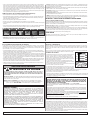
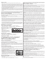
• Select the first board. All
installations should begin with the
groove side against the wall using
the longest boards available.
Apply a continuous 1/8″ (3 mm)
glue bead to the inside bottom of
the groove on the end of the
board. Do not apply glue to the
groove side at this time (Item C,
Figure 14). Products with the end
tongue on the left should be
installed right to left, opposite
tongues should be left to right
(Item D, Figure 14). If a sacrificial
board was used DO NOT glue
the first row to it.
• Complete the first row. Cut the last board allowing for 1/2″ (13 mm) clearance between the wall
and the floor. (Use the remaining end of the cut board as a starter board for any row following row three). Install a wedge on the
end of the board between the hardwood flooring and the wall, allowing 1/2″ (13 mm) expansion space. Avoid installation of any
boards shorter than 16″ (40.6 cm) in the first four rows (Item F, Figure 14).
• Use a pull bar to pull the last board into place from the opposite end. Install wedges into the gap and tighten (Item B, Figure 14).
• If any glue gets on the surface of the flooring, wipe off immediately with a clean damp cloth.
Figure 11
16
″
(40.6 cm)
C
Starter Strip
Wooden Wedges
Underlayment
A
D
F
B
G
E
Always work directly in front of the plank
you are installing. Never stand or sit on any
of the planks you have already installed.
Apply a
1/8″ (3 mm)
bead along
the inside
bottom of
the end
and side
groove.
“Work Zone”
Figure 14
Underlayment will install
parallel to longest wall
Pre-measured overlap
Underlayment
Les panneaux di renforcement
doivent être installés parallèlement
au mur le plus long.
Zone de recouvrement de panneaux
de renforcement pré-mesurée.
Panneaux de renforcement
El recubrimiento inferior se
instala en sentido paralelo
a la pared más larga
Superposición incluida
Recubrimiento inferior
Figure 12
chalk line
work area - adhesive
Figure 10a
chalk line
w
ork area - adhesive
groove side
231
Figure 10b
F
igure 10c
12 3
10 11 12
13
456
78 9
Figure 10d
45
˚
-90
˚
Figure 9
Figure 13
4
-
6
(10-15 cm)
F
igure 5
Figure 6
S
TARTING WALL
Multiple of width of
product + 1/4
″
(6 mm)
[1/2
″
(13 mm) for
floating floors] expansion
C
halk line
Figure 4
P
referred Alignment
face nail every
6″ (15 cm)
1st row 1st row
2nd row
blind nail into
t
ongue every
3
–4″ (8-10 cm)
tongue
chalk line
Figure 7
Wood Plank
Figure 8
Too Low
Correct
Too High
3

Conditions du sous-plancher
• PROPRE - Enlever toute trace de cire, de peinture, d’huile, de produits d’étanchéité, d’adhésifs et d’autres débris.
• HORIZONTAL/PLAT - À une tolérance maximale de 5 mm sur 3 m (3/16 po sur 10 pi) ou de 3 mm sur 2 m (1/8 po sur 6 pi). Poncer
les bosses et les joints. Si le plancher doit être collé, remplir les creux de produit de surfaçage en ciment à additif de latex d’une
résistance à la compression d’au moins 20 000 kPa (3 000 lb/po
2
), tel que le produit S-194 Armstrong ou l’enduit de ragréage pour
sous-plancher et surface gaufrée avec additif de sous-couche S-195. Suivre le mode d’emploi du fabricant du produit et s’assurer
que ledit produit est entièrement SEC avant de commencer la pose du plancher. En cas de pose du plancher avec attaches
mécaniques, éliminer les creux à l’aide de 6 couches maximum de feutre de construction de 15 lb, de contreplaqué ou de cales
(pas de produits de surfaçage). Les matériaux utilisés doivent fournir une surface de sous-plancher solide qui ne réduira pas la
résistance à l’arrachement des attaches mécaniques.
• SEC - Vérifier la teneur en humidité du sous-plancher à l’aide d’un humidimètre approprié. Les sous-planchers en béton doivent
avoir été terminés depuis au moins 30 jours avant de faire un essai.
4
AVIS IMPORTANT SUR LA SANTÉ POUR LES RÉSIDENTS DU
MINNESOTA SEULEMENT :
CES MATÉRIAUX DE CONSTRUCTION ÉMETTENT DU FORMALDÉHYDE. DES CAS D’IRRITATION DES
YEUX, DES VOIES NASALES ET DE LA GORGE, DE MAUX DE TÊTE, DE NAUSÉES ET D’AUTRES
SYMPTÔMES POUVANT SUGGÉRER L’ASTHME, TELS QUE L’ESSOUFFLEMENT, ONT ÉTÉ SIGNALÉS APRÈS
UNE EXPOSITION AU FORMALDÉHYDE. LES PERSONNES ÂGÉES ET LES ENFANTS, AINSI QUE TOUTE
PERSONNE DÉJÀ SUJETTE À L’ASTHME, AUX ALLERGIES OU À DES TROUBLES
PULMONAIRES, COURENT DE PLUS GRANDS RISQUES. LA RECHERCHE SE POURSUIT SUR LES EFFETS
POSSIBLES À LONG TERME DE L’EXPOSITION AU FORMALDÉHYDE.
UNE VENTILATION RÉDUITE PEUT PERMETTRE AU FORMALDÉHYDE ET À D’AUTRES CONTAMINANTS DE
L’AIR DE S’ACCUMULER À L’INTÉRIEUR. UNE TEMPÉRATURE ET UNE HUMIDITÉ AMBIANTES ÉLEVÉES
AUGMENTENT LES NIVEAUX DE FORMALDÉHYDE. LORSQU’UNE MAISON EST SITUÉE DANS UNE RÉGION
SUBISSANT DES TEMPÉRATURES TRÈS ÉLEVÉES EN ÉTÉ, ON PEUT UTILISER UN SYSTÈME DE
CLIMATISATION POUR CONTRÔLER LA TEMPÉRATURE INTÉRIEURE ET D’AUTRES APPAREILS DE
VENTILATION MÉCANIQUE POUR RÉDUIRE LES NIVEAUX DE FORMALDÉHYDE ET D’AUTRES
CONTAMINANTS DE L’AIR AMBIANT.
POUR TOUTE QUESTION CONCERNANT LES EFFETS DU FORMALDÉHYDE SUR LA SANTÉ, ON PEUT
CONSULTER SON MÉDECIN OU LE SERVICE SANITAIRE LOCAL.
II. PRÉPARATION
S
tockage et manutention
Manipuler et décharger avec précaution. Ranger dans un endroit sec en prévoyant un espace d’air d’environ 10 cm (4 po) sous les
c
artons stockés sur des sols en béton au niveau du sol. Le plancher ne doit pas être livré tant que le bâtiment n’est pas fermé à l’aide
de fenêtres et de portes installées et tant que les travaux de cimenterie, de plâtrage et autres travaux « humides » ne sont pas
terminés et secs.
Bien qu’il ne soit pas nécessaire d’acclimater le plancher haute performance, il vaut mieux le stocker avant son installation dans
l’endroit où il sera posé. Voir sur l’étiquette de l’adhésif les conditions de son stockage.
Conditions du chantier
•
Le bâtiment doit être fermé avec toutes les portes et les fenêtres extérieures installées.
Le béton, le ciment, la charpente, les murs secs, la peinture et les autres travaux «
humides » doivent être bien secs. Les revêtements muraux doivent être posés et la
p
einture terminée, sauf pour la dernière couche sur les plinthes. Autant que possible,
différer la pose des plinthes jusqu’à installation complète du plancher. Les sous-sols et
vides sanitaires doivent être secs et bien aérés.
•
Le terrassement extérieur doit être terminé, avec un drainage de surface à rampe
minimale de 7,6 cm sur 3,05 m (3 po sur 10 pi) permettant d’éloigner l’eau du bâtiment.
Toutes les gouttières et descentes d’eau doivent être installées.
• Le plancher haute performance peut être posé en dessous, au niveau ou au-dessus du
niveau du sol. Ne pas le poser dans une salle de bains.
• Les vides sanitaires doivent être à un minimum de 46 cm (18 po) entre le sol et le dessous
des solives. Un tapis de sol en pellicule polyéthylène noire de 6 à 20 mils est indispensable
comme pare-vapeur, avec joints se chevauchant sur 15 cm (6 po) et fixés avec du ruban
résistant à l’humidité. Le vide sanitaire doit posséder sur son périmètre une ventilation égale à un minimum de 1,5 % de la surface
du vide sanitaire. Les évents doivent être placés de façon à favoriser la ventilation transversale (Figure 1).
• Selon les besoins, les codes locaux ont préséance.
• Un système permanent de climatisation et de chauffage de l’air doit être installé et en état de service. La pièce concernée doit rester
à une température ambiante constante comprise entre 16 et 27 °C (60 et 80 °F) et à un taux d’humidité de 35 à 55 % pendant 14
jours avant la pose, pendant la pose et jusqu’à l’occupation.
Figure 1
2
e
étage (au-dessus
du niveau du sol)
1
e
r
étage
(niveau du sol)
Sous-sol (sous le
niveau du sol)
Niveau du
terrain
AVERTISSEMENT :
REVÊTEMENTS DE SOL SOUPLES DÉJÀ EN PLACE ET ADHÉSIF DE
ASPHALTE. ÉVITER DE PONCER, DE BALAYER OU DE GRATTE SEC, DE PERCER, DE SCIER, DE
DÉCAPER PAR JET DE BILLES, DE DÉCOUPER OU DE PULVÉRISER PAR DES MOYENS
MÉCANIQUES LES REVÊTEMENTS SOUPLES, LES ENDOS, LES THIBAUDES, LES ADHÉSIFS DE
BITUME FLUIDIFIÉ OU TOUT AUTRE ADHÉSIF.
Ces produits déjà en place peuvent contenir des fibres d’amiante et / ou de la silice cristalline.
Éviter de produire de la poussière. L’inhalation de telles poussières cancérigènes comporte un risque de lésion des
voies respiratoires.
L’usage du tabac combiné à une exposition aux fibres d’amiante accroît considérablement le risque de maladie grave.
À moins d’être certain que le produit déjà en place ne contient pas d’amiante, supposer le contraire. Le règlement peut
exiger, dans certains cas, de soumettre les matériaux à des essais pour en déterminer la teneur en amiante et prescrire
des méthodes pour enlever et éliminer ces produits.
Consulter l’édition courante de la brochure du Resilient Floor Covering Institute (RFCI), intitulée Recommended Work
Practices for Removal of Resilient Floor Coverings, pour obtenir des renseignements détaillés et des directives sur
l’enlèvement de revêtements de sol souples. Il est également possible de communiquer avec le détaillant ou
Armstrong World Industries, Inc. en composant le 1 800 233 3823.
Le revêtement de sol et l’adhésif fournis dans cette trousse NE contiennent AUCUN amiante.
Pour les détails de la garantie complet appelez 1 800 233 3823 ou visitez www.armstrong.com.
AVIS AUX INSTALLATEURS
ATTENTION À LA SCIURE
La sciure est produite en sciant, en ponçant ou en usinant les produits du bois. Cette sciure en
suspension dans l’air peut provoquer des irritations des voies respiratoires, des yeux et de la peau. Le
centre international de recherche sur le cancer (CIRC) a classé la sciure comme un cancérigène nasal
pour les humains.
Précautions à prendre : Tout outil électrique utilisé doit être équipé d’un collecteur de poussière. Si la quantité
de poussière dans l’air est élevée, utiliser un masque anti-poussières approprié, homologué par le NIOSH. Éviter le
contact de la sciure avec les yeux et la peau.
Premiers soins en cas d’irritation : Laver à grande eau la peau ou les yeux pendant au moins 15 minutes.
Pour obtenir une copie de la fiche signalétique de ce produit ou pour toute question technique ou concernant la pose,
prière de composer le
1 800 233 3823
ou visitez www.floorexpert.com, notre site Web technique.
• Cut or use a shorter board for the first board of the second row. Start the second row by applying a 1/8″ (3 mm) bead along the
i
nside bottom of the end and side groove of the new board. Install the first board of row two. Apply a bead of glue to the inside
bottom of the end and side groove of the next board and install. When installing boards together, use a tapping block against the
tongue, not the groove (Item G, Figure 14). Tap the boards into place by tapping with a hammer on the tapping block. DO NOT tap
o
n the edge directly with the hammer. Complete the second through fourth rows using this technique. Insert wedges on the ends,
as necessary, to restrain the movement of the floor.
• In the remaining rows, stagger joints 4″–6″ (10–15 cm) apart. Install the rest of the floor. Be sure all joints are tight. Use spacers
o
n the long and butt walls. Use a tapping bar to tighten the joints from the ends.
S
TEP 5: Complete the Installation
(All Installation Methods)
• Remove all tape and clean the floor with the recommended hardwood flooring cleaner.
• Trim all underlayment (floating only) and install or re-install any transition pieces, reducer strips, T-moldings, thresholds, bases
a
nd/or quarter round moldings that may be needed. These products are available pre-finished to blend with your flooring (see
below). Nail moldings into the wall, not the floor.
• Inspect the floor, filling all minor gaps with the appropriate blended filler.
• If the floor is to be covered, use a breathable material such as cardboard. Do not cover with plastic.
•
Leave warranty and floor care information with the owner. Advise them of the product name and code number of the flooring they
purchased.
• To prevent surface damage, avoid rolling heavy furniture and appliances on the floor. Use plywood, hardboard or appliance lifts if
n
ecessary. Use protective castors/castor cups or felt pads on the legs of furniture to prevent damage to the flooring.
V
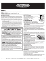
. TRANSITION AND WALL MOLDINGS
•
Reducer Strip: A teardrop-shaped molding used around fireplaces, doorways, as a room divider, or as a transition between wood
flooring and adjacent thinner floor coverings. Fasten down with adhesive, small nails or double-faced tape.
• Threshold: A molding undercut for use against sliding door tracks, fireplaces, carpet, ceramic tile, or existing thresholds to allow
f
or expansion space and to provide a smooth transition in height difference. Fasten to subfloor with adhesive and/or nails through
the heel. Pre-drill nail holes to prevent splitting.
• Stair Nosing: A molding undercut for use as a stair landings trim, elevated floor perimeters, and stair steps. Fasten down firmly with
a
dhesive and nails or screws. Pre-drill nail holes to prevent splitting.
• Quarter Round: A molding used to cover expansion space next to baseboards, case goods, and stair steps. Pre-drill and nail to
the vertical surface, not into the floor.
• Combination Base and Shoe: A molding used when a base is desired. Used to cover expansion space between the floor and the
w
all. Pre-drill and nail into the wall, not the floor.
• T-Molding: A molding used as a transition piece from one rigid flooring to another of similar height or to gain expansion spaces.
Fasten at the heel in the center of the molding. Additional rigid support may need to be added to the heel of the molding dependent
u
pon the thickness of the goods covered. Do not use this molding as a transition to carpet.
INSTALLERS— ADVISE YOUR CUSTOMER OF THE FOLLOWING
S
easons: Heating and Non-heating
R
ecognizing that hardwood floor dimensions will be slightly affected by varying levels of humidity within your building, care should
be taken to control humidity levels within the 35–55% range. To protect your investment and to assure that your floors provide lasting
satisfaction, we have provided our recommendations below.
• Heating Season (Dry): A humidifier is recommended to prevent excessive shrinkage in hardwood floors due to low humidity
levels. Wood stoves and electric heat tend to create very dry conditions.
•
Non-Heating Season (Humid, Wet): Proper humidity levels can be maintained by use of an air conditioner, dehumidifier, or by
turning on your heating system periodically during the summer months. Avoid excessive exposure to water from tracking during
periods of inclement weather. Do not obstruct in any way the expansion joint around the perimeter of your floor.
N
OTE: Final inspection by the end-user should occur from a standing position.
FLOOR REPAIR
Minor damage can be repaired with a Bruce
®
, Armstrong
®
or Robbins
®
touch-up kit or filler. Major damage will require board
r
eplacement, which can be done by a professional floor installer.
Reducer Strip Threshold Stair Nosing Quarter Round Combination Base
a
nd Shoe
T
-Molding
I. GÉNÉRALITÉS
Responsabilité du propriétaire/de l’installateur
Les jolis planchers en bois dur sont un produit de la nature et sont donc imparfaits. Nos planchers en bois sont fabriqués
conformément aux normes de l’industrie, avec des tolérances de défauts ne pouvant dépasser 5 %. Ces défauts peuvent être naturels
o
u dus à la fabrication. Lorsque le plancher est commandé, il faut ajouter 5 % à la surface réelle nécessaire pour tenir compte des
coupes et des défauts (10 % pour la pose de planches en diagonale).
• Le propriétaire/L’installateur assume toutes les responsabilités en ce qui concerne la dernière inspection de la qualité du produit.
L
’inspection du matériau doit être effectuée avant l’installation. Examiner avec soin la couleur, le fini et la qualité du matériau avant de
l’installer. S’il n’est pas acceptable, ne pas l’installer et en aviser immédiatement le vendeur.
•
Avant l’installation de tout plancher en bois, le propriétaire/l’installateur doit s’assurer que les surfaces concernées sont conformes ou
supérieures à toutes les normes applicables. Il faut respecter les recommandations des constructeurs et fabricants de matériaux, ainsi
que les codes locaux. Par ces instructions, il est recommandé que les éléments de la construction et le sous-plancher soient propres,
s
ecs, rigides, plats et d’une structure solide. Le fabricant décline toute responsabilité en cas de défaillance provenant d’un défaut du
sous-plancher, de la surface de pose ou du chantier lui-même.
• Avant installation, il appartient à l’installateur/au propriétaire de vérifier la qualité, la fabrication et la finition usine. Il doit sélectionner
l
es planches et, de façon raisonnable, rejeter ou découper toute planche défectueuse, quelle que soit la cause du défaut. En cas de
doute quant à la qualité, la fabrication ou la finition usine d’une planche, l’installateur ne doit pas utiliser ladite planche.
• L’utilisation de teinture, de bouche-pores, de mastic de retouche ou de tout autre produit approprié pour corriger les fentes du
sous-plancher est autorisée lors de la pose normale d’un plancher.
Page is loading ...
Page is loading ...
Page is loading ...
Page is loading ...
Page is loading ...
Page is loading ...
-
 1
1
-
 2
2
-
 3
3
-
 4
4
-
 5
5
-
 6
6
-
 7
7
-
 8
8
-
 9
9
-
 10
10


Bruce EVS3231 Installation guide
- Type
- Installation guide
- This manual is also suitable for
Ask a question and I''ll find the answer in the document
Finding information in a document is now easier with AI
in other languages
- français: Bruce EVS3231 Guide d'installation
- español: Bruce EVS3231 Guía de instalación
Related papers
-
 Bruce EMPS53H40S Installation guide
-
 Bruce EMLW54L88W Installation guide
-
 Bruce C5012 Installation guide
-
 Bruce EAHHD75L402 Installation guide
-
 Bruce ABC426 Installation guide
-
 Bruce ABC426 Installation guide
-
Unbranded SHD5362 Installation guide
-
Bruce SKFR29M10S Installation guide
-
-
 Bruce EKWR54L30S Installation guide


Other documents
-
QuicPrep A63710 Installation guide
-
 CalFlor PB71302 User manual
-
 Technoflex M2000-100HD User manual
-
Mohawk HCE34-20 User guide
-
Allen + Roth AR300 Installation guide
-
Shaw DH85805013 Installation guide
-
-
Armstrong Flooring A6100761 Installation guide
-
Armstrong Flooring A6545MX1 Installation guide
-
Armstrong U504065P User manual

