Page is loading ...

WARNING:
EXISTING IN-PLACE RESILIENT FLOOR COVERING AND ASPHALTIC
ADHESIVES. DO NOT SAND, DRY SWEEP, DRY SCRAPE, DRILL, SAW, BEADBLAST, OR
MECHANICALLY CHIP OR PULVERIZE EXISTING RESILIENT FLOORING, BACKING, LINING
FELT, ASPHALTIC “CUTBACK” ADHESIVE, OR OTHER ADHESIVE.
These existing in-place products may contain asbestos fibers and/or crystalline silica.
Avoid creating dust. Inhalation of such dust is a cancer and respiratory tract hazard.
Smoking by individuals exposed to asbestos fibers greatly increases the risk of serious bodily harm.
Unless positively certain that the existing in-place product is a non-asbestos-containing material, you must
presume it contains asbestos. Regulations may require that the material be tested to determine asbestos
content and may govern removal and disposal of material.
See current edition of the Resilient Floor Covering Institute (RFCI) publication Recommended Work Practices
for Removal of Resilient Floor Coverings for instructions on removing all resilient floor covering structures or
contact your retailer or AHF Products Inc. 1 800 233 3823.
The floor covering or adhesive in this package does NOT contain asbestos.
INSTALLATION INSTRUCTIONS
HYDROPEL LOCKING HARDWOOD
WITH Angle/Angle TECHNOLOGY
FOR FLOATING APPLICATIONS
RECOMMENDED CLEANER: Bruce Hardwood & Laminate Floor Cleaner or Armstrong Hardwood & Laminate Floor
Cleaner
RECOMMENDED UNDERLAYMENT (Floating installation system only): Quiet Comfort Premium or Quiet Comfort
RECOMMENDED WOOD GLUE (Floating installation and joint gluing): Armstrong EverSeal
™
Adhesive
For complete warranty information call 1 800 233 3823 or visit www.armstrong.com/hardwoodinstallationguides.
II. PREPARATION
Tools & Accessories Needed
• Broom • Pencil • Safety glasses • Matching filler
• Moisture meter (wood, concrete or both) • Transition and wall moldings as needed
• Hand saw, table saw, circular saw or band saw
• Armstrong Quiet Comfort Premium Or Armstrong Quiet Comfort
• Tape measure • Carpenter square • Hammer or rubber mallet
• Vinyl/plastic tapping block • Pull-bar • Utility knife
• NIOSH – designated dust mask • Recommended wood glue
• 3M Scotch-Blue
™
2080 Tape
III. SUBFLOOR CONDITIONS
Floating floors may be installed over any subfloor that is structurally sound, flat, clean
and dry on all grade levels. All substrates must meet or exceed all applicable building
codes and be:
• CLEAN – Subfloor must be free of wax, paint, oil, sealers, adhesives and other debris.
• FLAT – Within 3/16˝ in 10´ (5 mm in 3 m) and/or 1/8˝ in 6´ (3 mm in 2 m). Sand high areas or joints. Fill low areas with a
latex additive cementitious leveling compound of 3,000-PSI minimum compressive strength. Follow the instructions of the
leveling compound manufacturer. Leveling compounds must be tested for moisture to ensure they are within the specified
requirements for proper installation.
• DRY – Check and document moisture content of the subfloor using the appropriate moisture test. Moisture content of wood
subfloors must not exceed 13% on a wood moisture meter, or read more than a 4% difference from the moisture level of the
product being installed.
• STRUCTURALLY SOUND – Nail or screw any loose areas that squeak. Wood panels should exhibit an adequate nailing
pattern. A typical pattern is 6˝ (15 cm) along bearing edges and 12˝ (30 cm) along intermediate supports. Flatten edge swell
as necessary. Replace any water-damaged, swollen or delaminated subflooring or underlayments.
NOTE: Avoid subfloors with excessive vertical movement. Optimum performance of hardwood floor covering products
occurs when there is little horizontal or vertical movement of the subfloor. If the subfloor has excessive vertical movement
(deflection) before the installation of the flooring it is likely it will do so after installation of the flooring is complete. As flooring
manufacturers we are unable to evaluate each engineered system. Spacing and spans, as well as their engineering methods, are
the responsibility of the builder, engineer, architect on consumer, who is better able to evaluate the expected result based on site
related performance.
Concrete
(Floating Installations Only)
The flooring can be glued directly to concrete with a minimum compressive strength of 3000 PSI. Do not install over a concrete
sealer or painted concrete. If present, remove by grinding or sanding. Do not install over slick, heavily troweled or burnished
concrete. Roughen the surface as necessary by sanding or grinding. Use an appropriate NIOSH-designated dust mask. Floating
floors can be installed over any structurally sound concrete.
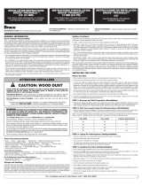
Concrete Moisture Tests
All concrete subfloors should be tested, and results documented, for
moisture content. Visual checks may not be reliable. Test several areas,
especially near exterior walls and walls containing plumbing. Acceptable test
methods for subfloor moisture content include:
• Tramex Concrete Moisture Encounter Meter (Figure 3): Moisture
readings should not exceed 4.5 on the upper scale. (Figure 3 shows an
unacceptable reading of over 4.5.)
• Polyfilm Test: Apply 3´ x 3´ (1 m x 1 m) pieces of polyethylene film to the
subfloor and leave in place for 24 hours. Assure all edges are completely
sealed with water resistant tape. Darkened concrete or condensation
on film indicates presence of moisture and requires additional
measurements with the Tramex Meter, Calcium Chloride or RH test.
NOTE: The following tests are required in commercial applications. Either or both tests are acceptable.
•
Calcium Chloride Test (ASTM F 1869): The maximum moisture transfer must not exceed 3 lbs./1000 ft.
2
in 24 hrs. With this test.
• RH Levels in Concrete Using In-situ Probes (ASTM F 2170) should not exceed 75%.
“DRY” CONCRETE, AS DEFINED BY THESE TESTS CAN BE WET AT OTHER TIMES OF THE YEAR. THESE TESTS DO NOT
GUARANTEE A DRY SLAB. ALL NEW CONSTRUCTION CONCRETE SLABS SHOULD HAVE A MINIMUM OF 10 MIL POLY FILM
MOISTURE BARRIER BETWEEN THE GROUND AND THE CONCRETE.
Moisture Retardant Systems
If excessive moisture is present or anticipated, use Professional Moisture Retardant System, Armstrong Summit Select adhesive
or inexpensive sheet vinyl to reduce vapor intrusion.
• Sheet vinyl: An inexpensive sheet vinyl or “slip-sheet” (felt-backed with vinyl wear layer) may be installed. Use a premium
grade, alkali resistant adhesive and a full spread application system to properly bond the vinyl to the subfloor. Follow the
sheet vinyl manufacturer’s instructions for installation procedures. A bond test may be required as an adhesion test. Install
several small areas (3´ x 3´) (1 m x 1 m) and allow the vinyl to set for 72 hours. Remove the vinyl. If the backing remains
attached to the concrete, the subfloor should be acceptable for sheet vinyl installation. Install the sheet vinyl and allow the
adhesive to cure for 24 hours prior to beginning installation. Degloss as necessary to create an adequate adhesive bond.
Always check for adequate adhesive bond.
Acoustic Concrete
(Floating Installations Only)
Acoustic concrete normally contains large quantities of gypsum that may inhibit the adhesive’s capability to properly bond.
Acoustic concrete must be primed with the concrete manufacturer’s recommended primer/surface hardener. Test the concrete
by scraping the surface with a nail or other sharp object. If the concrete powders or crumbles, it is not sound and suitable for
direct application of hardwood flooring and may require the use of a floating sub-floor system. Always check for adequate
adhesive bond. The concrete must have a minimum compressive strength of 2000 PSI.
Ceramic, Terrazzo, Slate & Marble
(Floating Installations Only)
All grout joints and broken corners that exceed 3/16˝ (5 mm) must be filled with a cementitous leveling compound. The surface
should be cleaned and abraded to create a good bonding surface for the adhesive. Loose tiles must be re-adhered to the
subfloor or filled as above. Remove all sealers and surface treatments. Always check for adequate adhesive bond.
I. GENERAL INFORMATION
Owner/Installer Responsibility
NOTE: Locking hardwood flooring is installed using a floating floor installation. A 1/2˝ expansion zone must be maintained at
all vertical obstructions including doorways and transition strips. The flooring cannot be fit tight against any vertical surface
such as stairways, walls or pipes. Do not attach or pinch the flooring to the subfloor at any point in the installation when using a
floating installation, including gluing, nailing or by any other methods. Do not restrict horizontal motion of the floor by wedging
planks under other surfaces, such as door jambs, base molding, or existing transition strips.
Beautiful hardwood floors are a product of nature and therefore, not perfect. Our hardwood floors are manufactured in
accordance with accepted industry standards, which permit grading deficiencies not to exceed 5%. These grading deficiencies
may be of a manufacturing or natural type. When flooring is ordered, 5% must be added to the actual square footage needed for
cutting and grading allowance (10% for diagonal installations).
• The owner/installer assumes all responsibility for final inspection of product quality. Inspection of all flooring should be done
prior to installation. Carefully examine flooring for color, finish and quality before installing it. If material is not acceptable, do
not install it. Contact the seller immediately.
• Prior to installation of any hardwood flooring product, the owner/installer must determine that the job-site environment and
the sub-surfaces involved meet or exceed all applicable standards. Recommendations of the construction and materials
industries, as well as local codes, must be followed. These instructions recommend that the construction and subfloor be
clean, dry, stiff, structurally sound and flat. The manufacturer declines any responsibility for job failure resulting from, or
associated with, subfloor and substrates or job-site environmental deficiencies.
• Prior to installation, the owner/installer has final inspection responsibility as to grade, manufacture and factory finish. The
installer must use reasonable selectivity and hold out or cut off pieces with deficiencies, whatever the cause. Should an
individual piece be doubtful as to grade, manufacture or factory finish, the installer should not use the piece.
• Use of stain, filler or putty stick for touch-up and appropriate products for correcting subfloor voids is accepted as part of
normal installation procedures.
1
ATTENTION INSTALLERS
CAUTION: WOOD DUST
Sawing, sanding and machining wood products can produce wood dust. Airborne wood dust
can cause respiratory, eye and skin irritation. The International Agency for Research on Cancer
(IARC) has classified wood dust as a nasal carcinogen in humans.
Precautionary Measures: If power tools are used, they should be equipped with a dust collector. If high dust
levels are encountered, use an appropriate NIOSH-designated dust mask. Avoid dust contact with eye and skin.
First Aid Measures in Case of Irritation: In case of irritation, flush eyes or skin with water for at least 15 minutes.
If you have any technical or installation questions, or to request a Material Safety Data Sheet,
please call 1 800 233 3823 or visit www.floorexpert.com, our technical website.
IMPORTANT HEALTH NOTICE FOR MINNESOTA RESIDENTS ONLY: THESE BUILDING MATERIALS
EMIT FORMALDEHYDE. EYE, NOSE, AND THROAT IRRITATION, HEADACHE, NAUSEA AND A VARIETY OF ASTHMA-LIKE
SYMPTOMS, INCLUDING SHORTNESS OF BREATH, HAVE BEEN REPORTED AS A RESULT OF FORMALDEHYDE EXPOSURE.
ELDERLY PERSONS AND YOUNG CHILDREN, AS WELL AS ANYONE WITH A HISTORY OF ASTHMA, ALLERGIES, OR
LUNG PROBLEMS, MAY BE AT GREATER RISK. RESEARCH IS CONTINUING ON THE POSSIBLE LONG-TERM EFFECTS OF
EXPOSURE TO FORMALDEHYDE.
REDUCED VENTILATION MAY ALLOW FORMALDEHYDE AND OTHER CONTAMINANTS TO ACCUMULATE IN THE INDOOR
AIR. HIGH INDOOR TEMPERATURES AND HUMIDITY RAISE FORMALDEHYDE LEVELS. WHEN A HOME IS LOCATED IN
AREAS SUBJECT TO EXTREME SUMMER TEMPERATURES, AN AIR-CONDITIONING SYSTEM CAN BE USED TO CONTROL
INDOOR TEMPERATURE LEVELS. OTHER MEANS OF CONTROLLED MECHANICAL VENTILATION CAN BE USED TO REDUCE
LEVELS OF FORMALDEHYDE AND OTHER INDOOR AIR CONTAMINANTS. IF YOU HAVE ANY QUESTIONS REGARDING THE
HEALTH EFFECTS OF FORMALDEHYDE, CONSULT YOUR DOCTOR OR LOCAL HEALTH DEPARTMENT.
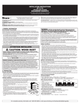
Soil Line
2nd Floor
(above ground level)
1st Floor
(ground level)
Basement
(below ground level)
Figure 1
Figure 3

Acoustic Cork Underlayment
(Floating Installations Only)
The flooring can be glued or floated directly over full-spread, permanently bonded acoustic cork. The cork should have a density
of no less than 11.4 lb./cubic foot. The cork, in general, should be pure cork combined with a polyurethane or resin binder.
Install cork in accordance with cork manufacturer’s recommendations. Always check for adequate adhesive bond. When floating
floors over cork DO NOT use foam underlayment.
Wood Subfloors and Underlayment
(Floating Installations Only)
General: The wood subflooring materials must not exceed 13% moisture content. Using a reliable wood moisture meter, measure
moisture content of both the subfloor and the hardwood flooring to determine proper moisture content. The difference between
the moisture content of the wood subfloor and the hardwood flooring must not exceed 4%. When installing parallel to the
floor joists it may be necessary to stiffen the subfloor system by installing an additional minimum of 3/8˝ (9.5 mm) approved
underlayment. Applicable standards and recommendations of the construction and materials industries must be met or exceeded.
NOTE: As flooring manufacturers, we are unable to evaluate each engineered system. Spacing and spans, as well as their
engineering methods, are the responsibility of the builder, engineer, architect or consumer who is better able to evaluate the
expected result based on site-related conditions and performance. The general information provided below describes common,
non-engineered joist/subfloor systems. Engineered flooring systems may allow for wider joist spacing and thinner subflooring
materials
.
Wood Structural Panel Subfloors and Underlayment
(Floating Installations Only)
Structural panels/underlayment must be installed sealed side down. When used as a subfloor, allow 1/8˝ (3 mm) expansion
space between each panel. If spacing is inadequate, cut in with a circular saw. Do not cut in expansion space on tongue and
groove panels.
• Plywood: Must be minimum CDX grade (exposure 1) and meet US Voluntary Product Standard PS1 performance standard or
Canadian performance standard CAN/CSA 0325-0-92. The preferred thickness is 3/4˝ (19 mm) as a subfloor [minimum 5/8˝
(16 mm)] or 3/8˝ (9.5 mm) as underlayment.
• Oriented Strand Board (OSB): Conforming to US Voluntary Product Standard PS2 or Canadian performance standard CAN/
CSA 0325-0-92 construction sheathing. Check underside of panel for codes. When used as a subfloor, the panels must be
tongue and groove and installed sealed side down. Minimum thickness to be 23/32˝ (18 mm) thick when used as a subfloor
or 3/8˝ (9.5 mm) as underlayment.
• Waferboard and Chipboard: Conforming to US Voluntary Product Standard PS2 or Canadian performance standard CAN/CSA
0325-0-92. Must be 3/4˝ (19 mm) thick when used as a subfloor and 3/8˝ (9.5 mm) thick when used as an underlayment.
• Particleboard: Must be a minimum 40-lb. density, stamped underlayment grade and 3/4˝ (19 mm) thick.
Solid Wood Subfloors
(Floating Installations Only)
• Minimum 3/4˝ (19 mm) thick with a maximum width of 6˝ (15 cm) installed at a 45˚ angle to the floor joists.
• Group 1 dense softwood (Pine, Larch, Douglas Fir, etc.) No. 2 common, kiln dried with all board ends bearing on joists.
• For glue down applications add 3/8˝ (9.5 mm) approved underlayment.
Existing Wood Flooring
(Floating Installations Only)
• Existing engineered flooring must be well bonded/fastened. When gluing over existing wood flooring of any thickness, the
finishing materials must be abraded or removed to foster an adequate adhesive bond. When flooring is to be mechanically
fastened, the existing engineered wood flooring must be a minimum of 3/8˝ (9.5 mm) thick installed over approved wood/
wood composite underlayment that has been properly fastened. When installing over engineered flooring that is glued to
concrete, the minimum thickness of that flooring must be 1/2˝ (13 mm) to allow for the length of the fastener.
• Existing solid wood flooring that exceeds 6˝ (15 mm) in width must be covered with 3/8˝ (9.5 mm) approved underlayment
and fastened as required. Do not install over solid flooring attached directly to the concrete.
IV. INSTALLING THE FLOOR
Before You Start
• Before installing the planks, central heat or air conditioning should be operating for 14 days.
• Install only at room temperature above 60˚F (16˚C) and 35-55% humidity conditions.
• In rooms with under-floor (radiant) heating, the surface temperature of the subfloor may not, under any circumstances,
exceed 85˚F (29˚C). Increasing heat should be done in 5-degree increments. Ascertain that the subfloor is properly engineered
or controlled for the flooring being installed. Subfloors designed for materials with higher resistance to heat transfer, such as
carpet, WILL damage the flooring. Installations that include multiple floor covering products on a single heating circuit must
be adjusted for the flooring product with the highest heat transfer or lowest temperature requirement.
• When possible, preselect and set aside boards that blend best with all horizontally mounted moldings (reducer/stair nose
etc.) This will assure a uniform final appearance. Install these boards adjoining the moldings.
• Floor should be installed from several cartons at the same time to ensure good color and shade mixture.
• Be attentive to staggering the ends of the boards at least 6˝ (15 cm) when possible, in adjacent rows. This will help ensure a
more favorable overall appearance of the floor.
STEP 1: Doorway and Wall Preparation
(Floating Installations)
• Undercut door casings and jambs. Remove any existing base, shoe mold or doorway thresholds. These items can be replaced
after installation. When undercutting door casings the installer should confirm there is the recommended expansion space.
The floor must have 1/16˝ clearance under the door casing to be able to float freely without vertical restriction.
STEP 2: Plan Your Layout Using the Following Steps
(Floating Installations)
• Decide the direction of the floor installation in the room. Planks installed parallel to windows accent the floor the best. Floors
should be installed perpendicular to the floor joists. Stiffen subfloors as necessary to prevent vertical movement.
• NOTE: If your room exceeds a maximum room width of 30´ (9 m) or a maximum room length of 30´ (9 m) additional
expansion space is required. T- Moldings may be used at doorways or intersections to increase the expansion space.
STEP 3: Laying the Underlayment
(Floating Installations)
• Install the underlayment in the same direction that the hardwood
flooring is to be installed.
• Extend the underlayment a few inches up the wall.
• Trim excess prior to installing trim or moldings.
• The floating floor underlayment already has double-sided tape for
ease of taping the precut overlapping seams. If a non-adhesive
underlayment is used, tape all seams with the included tape.
STEP 4: Installing the First Row
(Floating Installations)
• Begin on the left side of the room and work right.
• Lay the first full piece with the small, tongue side facing the wall (Fig. 9).
• Install second and subsequent full pieces in the first row by aligning
short ends of boards and locking into place (Fig. 10).
• Use spacers along all sides that butt up against walls to maintain 1/4˝
(6.35 mm) to 1/2˝ (12.7 mm) expansion zone (Figs. 10 & 11).
• Continue laying boards in the first row until you need to cut the last
piece.
• Measure the distance between the wall and the face surface of the
last board. Subtract 1/4˝ (6.35 mm) and cut the board. (See cutting
instructions above.)
• If this distance is less than 8˝ (20.32 cm) go back to the first full plank
and cut approximately 8˝ (20.32 cm) from the end closest to the starting
wall. This will leave a longer piece at the end of the first row.
2
• When installing tile visuals, grout lines can be aligned or off-set. If the
tiles are being balanced in the room with equal-sized tile along each
wall, measurements and adjustments should be done before proceeding
to the second row.
STEP 5: Installing the Remaining Rows
(Floating Installations)
• Begin the second row of planks with the piece cut from the last piece
in the first row. If the piece is shorter than 8˝ (20.32 cm), cut a new
plank in half and use it to begin the second row. Whenever practical,
use the piece cut from the preceding row to start the next row. End
joints of all boards should be staggered 8” (20.32 cm) or more.
• Install the long end of the first board at an angle to the board in the
previous row. Keep this board at its natural angle slightly raised off the
subfloor (Fig. 13). Use a scrap piece of laminate to support the row if
needed.
• Continue installing full boards in the second row by angling the short
end of the next board in the row to lock into the previous board (Fig.
14). Position the board so that the long side of the board is close to
boards in the previous row and overlapping the groove of the boards
in the previous row.
• Angle up and push forward until the boards lock together (Fig. 15).
• Continue installing full boards in the second and subsequent rows until
you reach the wall on your right.
• Mark the last piece, cut and install. After all boards in the row are
installed, press or walk all boards flat to the subfloor to begin the next
row (Fig. 16).
• Use a pull bar when necessary to ensure joints are tight (Fig. 17).
STEP 6: Installing the Last Row
(Floating Installations)
• The last row in the installation may need to be cut lengthwise.
• Place the row of planks to be fit on top of the last row of installed
planks. Use a divider or a piece of the plank as a scribe to trace the
contour of the wall (Fig. 18).
• Be sure to place a spacer between the marking pen and “scribe” piece
of board. This adds the 1/4˝ (6.35 mm) to 1/2˝
(12.7 mm) space you need at the finish wall (Fig. 18).
• Mark where the board should be cut.
• If the fit at the finish wall is simple and straight, just measure for the
correct width and cut.
• After the last row is installed, use the pull bar to tighten the joints.
• When appropriate, cut the underlayment even with the top of the floor
(Fig. 19).
• Whenever practical, use cut pieces from previous rows as a starter
board to reduce waste.
• Maintain 6˝ (15 cm) spacing between end joints after the first four
rows for best appearance.
STEP 7: Installing Under a Door Jamb
(Floating Installations)
• Installations of locking engineered floors under moldings, such as a
door jamb, may require that the top lip of the groove on the end be
reduced in size.
• Using a small plane or knife plane, shave off the ledge off the groove.
• After the groove edge has been trimmed, place the board into place and tighten with a pull bar to test for fit. The installer
must be certain that the proper expansion space is maintained and the flooring is not pinched.
• If fit is incorrect, trim as necessary. Remove any wax from the end joint so you will get good adhesion.
• Place a bead of recommended wood glue on the bottom lip of the groove.
• Reinsert the tongue into the groove and tighten the board with a pull bar. Hold the board in place with painters tape (3M
Scotch-Blue
™
2080 Tape) until the glue is dry. Do not use masking tape or duct tape, as the finish may be damaged.
STEP 8: Completing the Installation
(All Installation Methods)
• Remove all wedges and tape if used.
• Clean floor with the recommended hardwood flooring cleaner.
• Trim all underlayment and install, or re-install, all base and/or quarter round moldings. Nail moldings into the wall, not the
floor. Inspect the floor, filling all minor gaps with the appropriate blended filler.
• If the floor is to be covered, use a breathable material such as cardboard. Do not cover with plastic.
• Leave warranty and floor care information with the owner. Advise them of the product name and code number of the flooring
they purchased.
• To prevent surface damage, avoid rolling heavy furniture and appliances on the floor. Use plywood, hardboard or appliance
lifts if necessary. Use protective castors/castor cups or felt pads on the legs of furniture to prevent damage to the flooring.
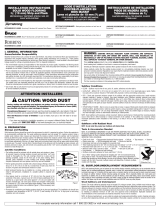
V. TRANSITION AND WALL MOLDINGS
• Reducer Strip: A teardrop shaped molding used around fireplaces, doorways, as a room divider, or as a transition between
hardwood flooring and adjacent thinner floor coverings. Fasten down with adhesive, small nails or double-faced tape.
• Threshold: A molding undercut for use against sliding door tracks, fireplaces, carpet, ceramic tile, or existing thresholds to
allow for expansion space and to provide a smooth transition in height difference. Fasten to subfloor with adhesive and/or
nails through the heel. Predrill nail holes to prevent splitting.
• Stair Nosing: A molding undercut for use as a stair landings trim, elevated floor perimeters, and stair steps. Fasten down
firmly with adhesive and nails or screws. Predrill nail holes to prevent splitting.
• Quarter Round: A molding used to cover expansion space next to baseboards, case goods, and stair steps. Predrill and nail
to the vertical surface, not into the floor.
• Combination Base and Shoe: A molding used when a base is desired. Used to cover expansion space between the floor and
the wall. Predrill and nail into the wall, not the floor.
• T-Molding: A molding used as a transition piece from one rigid flooring to another of similar height or to gain expansion
spaces. Fasten at the heel in the center of the molding. Additional rigid support may need to be added to the heel of the
molding dependent upon the thickness of the goods covered. Do not use this molding as a transition to carpet.
Reducer Strip Threshold Stair Nosing Quarter Round T-Molding
Figure 9
1/4"
Figure 11
Figure 10
Figure 13
Figure 14
Figure 15
Figure 16
Figure 17

3
All trademarks owned by AHF Proucts or its subsidiaries. © 2019 AHF Products
Scotch-Blue is a trademark of 3M.
AHF Products 2500 Columbia Ave., Lancaster, PA 17603
WB-1308-219
INSTALLERS – ADVISE YOUR CUSTOMER OF THE FOLLOWING
Seasons: Heating and Non-heating
Recognizing that hardwood floor dimensions will be slightly affected by varying levels of humidity within your building, care
should be taken to control humidity levels within the 35-55% range. To protect your investment and to assure that your floors
provide lasting satisfaction, we have provided our recommendations below.
• Heating Season (Dry): A humidifier is recommended to prevent excessive shrinkage in hardwood floors due to low humidity
levels. Wood stoves and electric heat tend to create very dry conditions.
• Non-Heating Season (Humid, Wet): Proper humidity levels can be maintained by use of an air conditioner, dehumidifier, or
by turning on your heating system periodically during the summer months. Avoid excessive exposure to water from tracking
during periods of inclement weather. Do not obstruct in any way the expansion joint around the perimeter of your floor.
/