
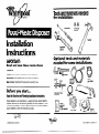
Installation
Instructions
IMPORTANT:
Read and save these instructions.
IMPORTANT:
Installer: Leave Installation Instructions with the homeowner.
Homeowner: Keep Installation Instructions for future reference
Save Installation Instructions for local electrical inspector’s use.
Before you start...
Read the Electrical and Plumbing Installation Instructions.
Proper installation is your responsibility A qualified technician should install this
disposer. Make sure you have everything necessary for correct installation. It is the
customer’s responsibility to contact qualified electrical and plumbing installers to
assure installation is correct and meets all local codes,
Tools and materials needed
for installation:
screwdriver
2
wire nuts
(size 54)
Optional tools and materials
needed for some installations:
- - pipe wre
plastic tube
dishwasher drain
connector
lch
or auger
worm
gear clamp
d
0”
on-off
Lb
0
electrical
0; (Et ampere
01996 Whirlpool Corporation
Form No./Part No. 71620/4211597

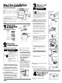
3
Remove old
disposer.
Start the installation
Installation dimensions
Garbage Disposer Dimensions
Electrical Shock Hazard
- II
Disconnect from electrical
SuPPlY.
Failure to do so could result
in death or electncal shock.
Compare your new disposer mountrng
assembly with the exrstrng mountrng.
If the mounting assemblres are the same,
complete Steps 3-A, B, D, E.
A. Using a pipe wrench, disconnect the drain
line where It attaches to the disposer waste
line pipe.
6. If old disposer mounting is the same as
your new one,
insert end of jam-breaker
wrench or screwdriver into right side of a
disposer mounting ring lug at top of
disposer. Hold disposer with other hand
Turn jam-breaker wrench or screwdriver
counterclockwrse until lug lines up with one
of the sink-mounting assembly screws.
B* - Distance from bottom of sink to center
line of disposer outlet, Add l/2 inch when
stainless steel sink is used.
C* - Lenqth of waste line oroe from center
line of dysposer outlet to end of waste line
pipe.
IMPORTANT: Plumb waste line to prevent
standing water In the disposer motor
housing.
Drawing shows just one model type.
Check that
all parts were
“;y
I
screw
I
included.
gasket
Caution: Potential Property Damage.
Hold disposer with one hand while
turning to prevent it from falling when
the mountrng ring is disconnected.
Failure to do so could result in damage
to cabinet or floor.
Drawing
shows just one model type.
Mounting
assembly
sink flange
F!!v
I
2 rubber
screw(s) metal flange
Remove disposer Go to Step 3-D.
C.
If old disposer mounting is different from
your new one,
remove the nuts on the
mounting ring usrng pliers or an adjustable
wrench. Remove old disposer. You may
need to remove a clamp or Mist the
disposer to remove it.
D.Turn disposer upside down and remove the
electrical plate.
mounting ring
and 3 screws
snap ring
2
Electrical
requirements
E* Use a screwdriver to remove the grounding
wire Remove wire nuts from power
wires. Separate disposer power wires
from the cable wires Loosen screw(s)
on strain relref and remove cable from the
disposer.
E.
A U.L.-listed conduit connector
must
be provided at the junction
box.
F.
It is the personal responsibrlity
and obligation of the customer to
contact a qualified electrician to
assure that the electrical installation
is adequate and is in conformance
with the National Electrical Code
ANSI/NFPA 704atest edition* and
all local codes and ordinances.
Copies of the standards listed
may be obtained from:
* National
Fire Protection
Association
Batterymarch Park
Quincy, Massachusetts 02269
G.For continuous feed models:
Install a 15- or 20-amp wall
Electrical ground is required on this
appliance.
If old disposer mounting is the same
as your new disposer mounting, go to
Step 5.
Electrical Shock Hazard
Electrrcal ground is required
on this appliance.
1 Do Not ground to a gas pipe
Do Not have a fuse In the neu-
tral or grounding circuit.
Check with a qualified
electrlcian if you are not sure
the appliance is properly
grounded.
Failure to follow these
instructions could result in
death or electric shock.
E Loosen screws and remove the mounting
ring and back-up rings. A hammer may be
needed to loosen nngs.
6 Push old sink sleeve up through the srnk hole
and remove.
A.
120 Volt, 60 Hz, AC only, 15 or 20 Ampere
fused electrical supply is required. (Time-
delay fuse or circuit breaker is recommended.)
It is recommended that a separate circuit
serving only this appliance be provided.
B.
THE DISPOSER MUST BE CONNECTED WITH
COPPER WIRE ONLY.
C. Wire sizes and connections must conform
to the requirements of the National Electrical
Code, ANSI/NFPA 704atest edition* and all
local codes and ordinances.
switch above the countertop and
junction box inside cabinet as
shown. (switch and electrical
wiring can be obtained locally.)
Position switch in a convenient
location. Connect switch to
junction box.
D.This appliance should be connected to the
fused-disconnect (or circuit breaker) box
through flexible, armored or nonmetallic
sheathed, copper cable (with grounding
wire>. The flexible armored cable extending
from the appliance should be connected
directly to the junction box.
H.Clean sealant from sink hole rim usrny a
screwdriver or putty knife to scrape away all
traces of putty or caulking from the sink hole
rim. Hole rim
must
be as clean as possible
for a yood, watertight seal.
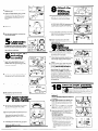
4
To install our
sink’s firs Y
disposer :
A.
Use wrench to loosen nut at top of
“P”-trap.
PANEL A

8
Attach the
upper
mounting
m m
6. Remove nut at top of sink strainer. Remove
extension pipe.
C.
Loosen the large-diameter nut at the base
of the strainer by placing the trp of a
screwdriver on the ridge of the nut and
gently tapping the screwdnver with a
hammer.
assembhr,
IA
gasket
A. Working from under sink, slip the ccond
rubber gasket, then the metal back-up ring
(flat side up>, up and over sink flange
8. Holding the rubber gasket and metal back-
up ring in place, attach the mounting ring to
the sleeve with the three mounting ring
screws Do Not tighten screws at this time.
D. Remove nut.
C.
Push rubber gasket, metal back-up ring and
mounting ring further up sink sleeve. Slide
snap ring onto sink sleeve until it pops Into
place in the sleeve yroove.
E.
Push the strarner assembly up through the
sink hole and remove
5
Clean sinkS
drain line.
If installing in a new home, go to Step 6.
Remove drain trap Using an auger, clean out
the horizontal drain pipe that runs from the
trap to the main waste pipe.
D.Tighten mounting screws until entire
mounting assembly is seated evenly and
tightly against sink.
1 D.t-i I
9
Make
electrical
connections
Watch these t&b
spots when routin
the auger.
l
A.
Remove electrical plate from the bottom
of the new disposer Pull out the black and
white electrical wires Locate the yreen
grounding screw under plate.
B. Insert strain relief Into hole Insert power
Separate the
mounting
assembly.
supply cable through strain relief. Pull cable
1 _
wires through opening where disposer
wires are located. Tighten strarn relief
screws.
C.
Connect power supply cable wires to the
disposer wires using electrical wire nuts or
by soldering wires together. Be sure to
connect
white to white, and black to
black.
Wrap wire connections with
electrical tape. Put wires back inside
disposer housing. Note: This appliance is
equipped with copper lead wires. If
connection is made to aluminum house
wiring, use only special connectors which
are approved for joining copper to
aluminum wires in accordance with the
national electrical code and local codes
and ordinances.
A Holding the mounting assembly with one
hand, use the other hand to insert jam-
breaker wrench into one of the lugs of the
lower mounting ring. Turn assemblycounter-
clockwise and remove.
B.
Loosen screws on mounting assembly until
they are level with mounting ring surface.
C.
Use screwdriver to pry off snap ring
Electrical ground is required on this appliance.
Failure to follow these instructions could result
sleeve 1
I
w
in death or electric shock.
D.
Take assembly apart and set aside
Electrical ground is required on this
appliance.
DO NOT reconnect electrical current to
main service panel until proper ground
is installed.
A.If
the cable leading to the disposer has
three wires,
attach the green grounding
wire to the green Qrounding screw. Go to
Step 10-D
B.
If the cable does NOT have a grounding
wire,
attach a length of copper wire (no
smaller than the other cable wire) to the
yreen yrounding screw
C.
Attach the other end of the grounding wire
to a yrounded metal cold water pipet
DO NOT ground to a gas supply line or
hot water supply line.
Use grounding clamp to secure wire to
pipe. If non-metal or plastic pipe IS used In
water connectrons or water supply you must
have a qualifted electrician install a proper
yround.
*Grounded cold water pipe must have metal
contlnulty to electrlcal ground and not be
Interrupted by plastic, rubber or other electrIcal-
lnsulatlny connectors such as hoses, flttlngs,
washers, or gaskets (Including water meter or
pump)
7
Apply rubber
s
asket or putty
o sink flange.
A.
The rubber sink flange gasket should always
be used where possible. Place rubber
gasket over sink flange. Go to Step 7-C.
IA. -
U
B.
If sink opening does not permit the use of a
rubber seal, plumber’s putty may be used.
Form putty into a long roll by rolling it
between your hands. Press roll under sink
flange rim.
C.
Place flange into sink drain hole. Push down
gently, but firmly to make sure flange sits
evenly over yasket or In putty
PANEL B

D.
Check to see if you have a water meter in
your home. To have a grounded water pipe,
the meter
must
have a wire clamp to either
side of the meter. You can yround the water
pipe by securely clamping a length of No. 6
copper wire for 200 amp service (or less> to
bare metal as shown Use yroundiny clamps,
certrfied by U.L., to attach wire to pipe.
I r- I
G.
If drain is too short,
measure how far
trap outlet is from tube and buy a drain trap
extensron with a slip nut. Install trap
extensron.
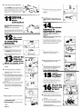
11
Optional
dishwasher
drain
connection
If you do not plan to connect a
dishwasher drain to the disposer, go to
Step 12.
Lay disposer on its side. Insert trp of
screwdriver at an angle into drain hole
opening. Tap screwdriver with hammer until
molded plug pops out. Remove loose plug
from disposer.
I-L When it
fits, tighten the
AID
nut on the trap.
For double sit& we recommend use df
separate traps for disposer and second
sink.
14
Optional:
Connect to
dishwasher drain.
If you do not plan to connect a
dishwasher drain to the disposer, go
to Step 15.
Make sure connections comply with
local plumbing codes.
A. A dishwasher drain connector kit may be
purchased from a hardware store. Use worm
year hose clamp on dishwasher connectron
Remove clamp or fitting from end of
dishwasher drain hose.
12
Connect
disposer
to mounting
assembb
1
A. /
A.
Lift the disposer and iositron it so that the
disposer’s three mounting ears are lined up
under
the ends of the sink mounting
assembly screws
6. Holding the disposer in place, turn the
lower mounting ring with ears to the nyht
until
all three
ears lock Into place In the
mounting assembly The drsposer will now
hang by Itself. The mounting ring will be
locked in place later.
B. Slrde large end of rubber coupler over
disposer inlet tube. Fasten coupler to
disposer with clamp provided.
13
Attach the
disposer
waste line
C.
Insert one end of the plastic tube into the
coupler and fasten with 7/e” clamp.
pipe to drain trap.
A.
Remove any foreign materials that may
have dropped Inside the disposer grinding
chamber
D.
Slip the gear hose clamp over the
dishwasher drain hose pushing it back 2-3
inches. Slip drain hose over plastic tube.
Slide clamp in place and tighten.
Be sure to tighten all three clamps.
B.
Turn the disposer around. Compare your
disposer waste line pipe with the two types
Illustrated in C and D. Attach waste line
pipe as specified.
15
lock
disposer
in place.
C.
If not already assembled, place the gasket
over the end of waste lrne pipe. Gasket must
be installed as shown to prevent leaking.
Insert tube Into disposer openrny. Place
flange over waste line pope and gasket.
Secure flange to disposer with screw
provided.
D. Insert the gasket into the disposer discharge
outlet. Gasket will be held in place by the
waste line pipe flange. Place flange over
waste line pipe. Secure flange and waste
line pipe to disposer wrth scretis)
provided.
Insert screwdriver orjam-breaker wrench
into left side of a disposer mounting lug
at the top of the drsposer. Turn screwdriver
or jam-breaker wrench to right until
disposer IS locked firmly In place.
MODELS
GClOOO
GC2000
GC3000
D.
16
Check for
leaks and
proper
operation.
A. Slovvly run water through unit. Then place
stopper seal In position and fill sink.
B.
Remove stopper and permit water to flow
Check for leaks at all plumbing connections
If there
IS
a leak, tighten the connection at
that point.
C. Turn on electrical power supply.
D.
Turn water on. Run dispenser for one minute.
Check that disposer
IS
operating correctly
Check for leaks at all plumbing connections
again. If there
IS
a leak, tighten the
connection at that point
E,Rotate disposer until waste line pipe aligns
with drain trap.
Make sure all connections comply with
local plumbing codes.
F. If tube is too long,
saw off excess tubing
with a hacksaw Make sure cut
IS
clean and
straight.
PANEL C

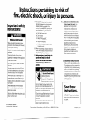
Instructions pertaining to risk of
fire, electric shock, or injury to persons.
Important safety
instructions:
PERSONAL INJURY HAZARD
When using electric appliances basic
precautions should always be followed,
including the following:
Read all the instructions before using the
appliance.
To reduce the risk of injury, close
supervision is necessary when appliance
is used near children.
Do not put fingers or hands into waste
disposer.
Turn the power switch to the OFF posi-
tion before attempting to clear a jam or
remove an object from the disposer,
When attempting to loosen a jam In a
waster disposer, use a self service jam-
breaker wrench as described in Use and
Care Guide.
When attempting to remove objects
from a waster disposer, use lony-han-
dled tongs or pliers.
Failure to follow these instructions could
result in serious injury.
01996 WhIrlpool Corporation
Form No./Part No. 71620/4211597
7. To reduce the risk of injury by materials
that may be expelled by a food-waste
disposer, place the stopper in the
drain/grind position when grinding Do
not put the followiny into a disposer:
a. Clam and oyster shells.
b.
Drain cleaner,
c. Glass, china or plastic.
d.
Large, whole bones.
e. Metal, such as bottle caps, tin cans,
or aluminum foil.
8. When not operating a disposer, leave the
drain cover in place to reduce the risk of
objects falling into the disposer
9. Before pressing red reset button, be
sure the wall
switch is In the off
position and on batch feed models
remove the stopper from the run
position.
Electrical Shock Hazard
Electrical ground is
required on this appliance.
Do Not ground to a gas pipe.
Do Not change the power supply cord
plug on cord connected appliances. If it
does not fit the outlet, have a proper outlet
installed by a qualified electrician.
Check with a qualified electrician if you are
not sure the appliance is properly
grounded.
Failure to follow these instructions could
result in death or electric shock.
For service information, call toll-free 1-800-253-l 301
10. a. GROUNDING INSTRUCTIONS FOR
CORD-CONNECTED UNITS.
This
appliance must be yrounded.
In the event of a malfunction or
breakdown, grounding provides a
path of least resrstance for electric
current to reduce the risk of electric
shock. If this appliance is equipped
with a cord having an equipment-
grounding conductor and a
grounding plug, the plug must be
plugged into an appropriate outlet
that is properly installed and
grounded in accordance with all
local codes and ordinances.
b. GROUNDING INSTRUCTIONS FOR
PERMANENTLY CONNECTED UNITS:
This appliance must be connected to
a grounded, metal, permanent wiring
system; or an equipment-grounding
conductor must be run wrth the clrcurt
conductors and connected to the
equipment-yroundiny terminal or lead
on the appliance.
Save these
instructions.
INSTALLER - Please leave Installation
Instructions with the homeowner or
occupant.
PrInted In U S A.
---
-
 1
1
-
 2
2
-
 3
3
-
 4
4
-
 5
5


Ask a question and I''ll find the answer in the document
Finding information in a document is now easier with AI
Related papers
-
Whirlpool GC2000 User manual
-
-
-
-
KitchenAid KSWX 0010 User guide
-
-
-
-
-
Other documents
-
-
 Drain Strain BRN 001 Installation guide
-
 Newport Brass 120/VB Installation guide
-
Everbilt 21-DSFS3-BN User manual
-
Newport Brass 121/10B Installation guide
-
InSinkErator FLG-BIS Installation guide
-
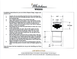
Whitehaus Collection WH202-HPOC Installation guide
-
 Whitehaus Collection WH202-ABRAS Installation guide
-
 Wyndham Collection WCS1000ESWHD28WH Operating instructions
-
Westbrass D2091-03 Installation guide


