Page is loading ...

PUBLISHED BY
Vaisala Oyj Phone (int.): +358 9 8949 1
P.O. Box 26 Fax: +358 9 8949 2227
FI-00421 Helsinki
Finland
Visit our Internet pages at www.vaisala.com.
© Vaisala 2011
No part of this manual may be reproduced in any form or by any means, electronic or
mechanical (including photocopying), nor may its contents be communicated to a third
party without prior written permission of the copyright holder.
The contents are subject to change without prior notice.
Please observe that this manual does not create any legally binding obligations for
Vaisala towards the customer or end user. All legally binding commitments and
agreements are included exclusively in the applicable supply contract or Conditions
of Sale.

QUICK GUIDE ____________________________________________________________________
4 ___________________________________________________________________ M211369EN-B
This page intentionally left blank.

___________________________________________________________________________ English
VAISALA________________________________________________________________________ 5
ENGLISH
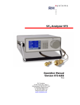
Product Overview
The Vaisala Multiparameter Transmitter DPT145 for SF
6
Gas combines
online measurement of dewpoint, pressure, and temperature. DPT145
also calculates four other parameters, including SF
6
density.
Main features of DPT145:
- Utilizes the Vaisala MPS1 multiparameter sensor with Vaisala’s
BAROCAP® and DRYCAP® technologies.
- Digital transmitter with a non-isolated RS-485 output.
- Compact size, well suited for integration into OEM systems.
- Delivered with an integrated adapter: DILO DN20, ABB Malmkvist,
or Alstom G1/2".
- Can be ordered assembled in a weather shield for outdoor
installations.
- Easy verification of dewpoint measurement with the Vaisala
DRYCAP® Hand-Held Dewpoint Meter DM70.
Output Parameters of DPT145
Parameter Abbreviation Metric Unit Non-Metric
Unit
Dewpoint/frost point temperature Tdf ºC ºF
Dewpoint/frost point temperature,
converted to atmospheric pressure
Tdfatm ºC ºF
ppm moisture, by volume H20 ppm ppm
Pressure, absolute P bara psia
Pressure, normalized to 20 °C
(68 °F)
Pnorm bara psia
Density Rhoo kg/m
3
kg/m
3
Temperature T ºC ºF
DPT145 with DILO DN20 Adapter

QUICK GUIDE ____________________________________________________________________
6 ___________________________________________________________________ M211369EN-B
Warning - Read Before Installation
CAUTION
Do not drop or hit the transmitter. The sensor is fragile
and may break from a sudden shock.
When transporting the transmitter, use the original
shipping box from Vaisala.
CAUTION
Do not open the connection between the adapter and
the transmitter. They are connected at the factory, and
the connection should remain unopened to guarantee
tightness.
Use tools only on the nut of the adapter, where the
transport protection cap is connected.
NOTE
Keep the transmitter dry and clean.
Do not remove the yellow transport protection cap
before you are ready to install the transmitter.
Uncapped transmitters will absorb moisture which will
affect the dewpoint measurement.
NOTE
Connect the transmitter directly to the main SF
6
gas volume, not behind a sampling line.
After installation, the transmitter will have a small
amount of moisture inside it. In still, dry gas it takes a
long time until vapor pressure inside the measurement
cell reaches equilibrium with the main gas tank. It is
not unusual for the stabilization of the dewpoint
reading to take several days after installation.

___________________________________________________________________________ English
VAISALA________________________________________________________________________ 7
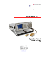
Transmitter Parts
5
6
7
8
3
4
1 2
DPT145 Transmitter Parts and Adapters
1 = Port I: Supply voltage only (optional, does not have to be used)
2 = Port II: RS-485 line and supply voltage
3 = Type label
4 = Connection between transmitter body and adapter – do not open
5 = DILO DN20 adapter: 50 mm nut with M45X2 inner thread
6 = ABB Malmkvist adapter
7 = Alstom G1/2" adapter
8 = Transport protection cap – remove only when ready to install

QUICK GUIDE ____________________________________________________________________
8 ___________________________________________________________________ M211369EN-B
Installation Without Weather Shield
1. Remove the yellow transport protection plug when
you are ready to install the transmitter.
2. Install the transmitter to the mechanical coupling
and tighten by hand.
3. Use a wrench to tighten the connection. Turn from
the adapter, not from the transmitter body!
Use sufficient force to achieve a tight installation.
The system must be leak-free for accurate
measurement.
4. For standard wiring, connect the cable to port II on
the transmitter.
Use a cable with a suitable connector for your
installation (straight or angled).
Let some of the cable hang from the back of the
transmitter, so that condensation cannot run along
the cable to the transmitter.

___________________________________________________________________________ English
VAISALA________________________________________________________________________ 9
Installation With Weather Shield
1. When DPT145 is ordered with the weather
shield, the transmitter is delivered already
attached to the shield.
If you have ordered the weather shield
separately, attach the transmitter to the
weather shield before continuing this
procedure. Fit the clamp of the weather shield
over the adapter, not the transmitter body.
For ABB Malmkvist and Alstom G1/2" type
adapters, place the clamp over the notches in
the adapter.
2. Use an 8 mm box-end wrench to loosen the
four bolts that hold the weather shield cover.
Remove the cover.
It is not necessary to remove the bolts, they
can remain in place during installation.
3. Remove the yellow transport protection plug.
Make sure the surfaces are clean and dry.

QUICK GUIDE ____________________________________________________________________
10 __________________________________________________________________ M211369EN-B
4. Install the transmitter to the mechanical
coupling and tighten by hand. Try to keep the
weather shield level.
5. Use a wrench to tighten the connection. Turn
from the adapter, not from the transmitter
body!
Use sufficient force to achieve a tight
installation. The system must be leak-free for
accurate measurement.
If the weather shield is tilted after the
installation, you can straighten it by loosening
the two nuts that keep the clamp tight.
Tighten the nuts after weather shield is
straight.
Note: The cable with the angled connector
has a fixed direction, and is designed to be
routed straight down from port II. If you
rotate the transmitter inside the weather
shield, or if you have the Alstom G1/2" type
adapter, you may have to use a cable with a
straight connector.

___________________________________________________________________________ English
VAISALA_______________________________________________________________________ 11
6. For standard wiring, connect the cable to port
II on the transmitter. Route the cable to the
cable clamp on the underside of the weather
shield. Attach the cable using a crosshead
screwdriver.
Let some of the cable hang from the back of
the transmitter, so that condensation cannot
run along the cable to the transmitter.
For cables with a straight connector:
move the rubber plug to the bottom hole and
route the cable from the back of the weather
shield.
7. Replace the weather shield cover using an
8 mm box-end wrench.

QUICK GUIDE ____________________________________________________________________
12 __________________________________________________________________ M211369EN-B
Wiring
Standard Wiring (Non-Isolated RS-485)
Connect supply voltage and RS-485 to port II. Port I does not need to be
used at all, and can remain covered.
15 ... 28 VDC
RS-485 +
RS-485 -
GND
+
SHIELD
-
1
2
3
4
2
4
13
Wire Colors for Vaisala Cables
Pin Connection on Port I Connection on Port II Wire Color
1 VDC supply+ VDC supply+ Brown
2 RS-485 D0- White
3 GND GND Blue
4 RS-485 D1+ Black
Note the following:
- The ground pin (pin 3) on both ports is internally connected to each
other and to transmitter chassis. The chassis connection is through a
1 MΩ resistor and a 40 nF capacitor that are connected in parallel.
- The frames of the M8 connectors are not connected to the chassis.
Alternate Wiring for Power Supply
If necessary, you can provide supply voltage using Port I, and only wire
RS-485 for Port II. Do not supply power from both ports.
1 = VDC+
3=GND
2
4
13
15 ... 28 VDC
+
-

___________________________________________________________________________ English
VAISALA_______________________________________________________________________ 13
Serial Line Operation
Default Serial Communication Settings
Property Description / Value
Baud rate 19200
Parity None
Data bits 8
Stop bits 1
Flow control None
Important Serial Commands
Command Description
R Start the outputting
S Stop the outputting
SEND [address] Output readings once (specify address for
transmitters in POLL mode)
FORM [modifier string] Set output format
? Device information
?? Device information (overrides POLL mode)
SMODE [mode] Show or set startup serial mode:
RUN, STOP, or POLL
MIXRATIO [0 ... 100] Show or set ratio (%) of SF
6
in the measured gas
ADDR [0 … 255] Show or set transmitter address
OPEN [0 … 255] Open a line to transmitter at defined address
CLOSE Close a line to a transmitter
RESET Reset the transmitter
HELP List of serial commands
Multiple Transmitters on RS-485 Line
By default, DPT145 transmitters are configured for single transmitter
operation. Serial operation mode is STOP and address is 0.
To configure transmitters for operation on a common line, you must give
each transmitter a unique address (range 0 ... 255) and set their serial
operation mode to POLL.
1. Connect the transmitter to the RS-485 line and power.
2. Change the address of the transmitter using the ADDR command:
addr [0...255]
3. Set the serial mode of the transmitter to POLL using the SMODE
command:
smode poll
4. Reset the transmitter to take the new settings into use.

QUICK GUIDE ____________________________________________________________________
14 __________________________________________________________________ M211369EN-B
Serial Output Examples and FORM Command
Command to set default output format:
form /
Output example (continuous output from RUN mode):
Tdf= 8.1 'C Tdfatm= 8.2 'C H2O= 10870 ppm P= 1.002 bara
Pnorm= 0.992 bara Rhoo= 6.0 kg/m3 T= 22.8 'C
Tdf= 8.1 'C Tdfatm= 8.2 'C H2O= 10878 ppm P= 1.002 bara
Pnorm= 0.992 bara Rhoo= 6.0 kg/m3 T= 22.8 'C
...
Command to set output format as Tdf and P with Modulus-256
checksum:
form 3.1 "Tdf=" Tdf U3 3.3 "P=" P " " U4 " " CS2 \r \n
Output example (continuous output from RUN mode):
Tdf= 12.5'C P= 0.949 bara 72
Tdf= 12.5'C P= 0.950 bara 6A
...
Technical Support
The complete DPT145 User's Guide is available in English at
www.vaisala.com/DPT145.
For technical questions, contact the Vaisala technical support by e-mail at
[email protected]. Provide at least the following supporting
information:
- Name and model of the product in question.
- Serial number of the product.
- Name and location of the installation site.
- Name and contact information of a technically competent person who
can provide further information on the problem.

___________________________________________________________________________ English
VAISALA_______________________________________________________________________ 15
Calibration and Adjustment
DPT145 is fully calibrated as shipped from factory. If there is a reason to
believe that device is not within the accuracy specifications, you can
perform a field check using an MI70 indicator and a suitable reference
probe. Vaisala recommends the following equipment for field checking:
- Vaisala DRYCAP® Hand-Held Dewpoint Meter DM70 with the
DMP74C probe is recommended for checking the dewpoint and
temperature measurement accuracy.
- For checking all parameters, you can use another DPT145 transmitter
as a reference.
- You also need a connection cable (Vaisala order code: 219980) to
connect the DPT145 to the MI70 indicator. If you have two DPT145
transmitters, you need two cables.
If the field check indicates that the DPT145 is not within its accuracy
specifications, contact a Vaisala Service Center or your local Vaisala
representative to have the DPT145 adjusted.
Product Returns
If the product must be returned for service, see www.vaisala.com/returns.
For contact information of Vaisala Service Centers, see
www.vaisala.com/servicecenters.
Warranty
Visit our Internet pages for more information and our standard warranty
terms and conditions: www.vaisala.com/warranty.
Please observe that any such warranty may not be valid in case of
damage due to normal wear and tear, exceptional operating conditions,
negligent handling or installation, or unauthorized modifications. Please
see the applicable supply contract or Conditions of Sale for details of the
warranty for each product.

QUICK GUIDE ____________________________________________________________________
16 __________________________________________________________________ M211369EN-B
Technical Data
Measured Parameters
Parameter Measured Range
Dewpoint -50 ... +30 °C (-58 ... +86 °F)
Pressure, absolute 1 ... 10 bar (14.5 ... 145 psi)
Temperature -40 ... +80 °C (-40 ... +176 °F)
Calculated Parameters
Parameter Measured Range
Pressure, normalized to 20 °C (68 °F) 1 ... 12 bara (14.5…174 psia)
SF
6
or SF
6
/N
2
mixture density 0 ... 100 kg/m
3
ppm moisture, by volume 40 ... 40 000 ppm
Dewpoint, converted to atmospheric
pressure
-65 … +30 °C (-85 ... +86 °F)
Performance
Property Description / Value
Dewpoint accuracy ±3 °C (±5.4 °F), see graph on
next page.
Dewpoint stability typical drift < 2 °C (3.6 °F)/5a
Pressure accuracy at 23 °C (73.4 °F) ±0.4 %FS
Pressure temperature dependence ±0.1 % FS/10 °C (18 °F)
Temperature accuracy
0 ... +40 °C (+32 ... +104 °F) ±0.5 °C (± 0.9 °F)
-40 ... +80 °C (-40 ... +176 °F) ±1 °C (± 1.8 °F)
Density accuracy (pure SF
6
, 1 ... 10 bara)
0 ... 40 °C (+32 ... +104 °F) ±1 %FS
-40 ... +60 °C (-40 ... +140 °F) ±2.2 %
ppm accuracy, typical
(5 ... 1000 ppm, 7 bar)
±(7 ppm + 15 % of reading)
Sensor response time
Pressure response time < 1 s
Dewpoint response time*
63% [90%] at 20°C and 1 bar
-50 -> -10 °C Tdf 5 s [10 s]
-10 -> -50 °C Tdf 10 s [2.5 min]
* system equilibrium related response
time is typically longer

___________________________________________________________________________ English
VAISALA_______________________________________________________________________ 17
020
20
0
10
30
-10
-20
-30
10
30 40 50 60
40
Dewpoint temperature (°C)
Temperature of measured gas (°C)
-40 -30 -20 -10 70 80
-40
-50
-60
Not recommended for
continuous measurement
Dewpoint measurement low limit
-70
Accuracy not specified
Accuracy
±3 °C Td
DPT145 Dewpoint Measurement Accuracy
Operating Environment
Property Description / Value
Operating temperature of electronics
-40 … +60 °C (-40 ... +140 °F)
Pressure
0 … 50 bar (0…725 psi)
Relative humidity 0 ... 100 %
Measured gases SF
6
SF
6
/N
2
mixture
Outputs
Property Description / Value
Digital output RS-485, non-isolated, Vaisala protocol
Connector 4-pin M8

QUICK GUIDE ____________________________________________________________________
18 __________________________________________________________________ M211369EN-B
General
Property Description / Value
Sensor Vaisala MPS1 multiparameter sensor
Operating voltage 15 ... 28 VDC
20 ... 28 VDC in cold temperatures
(-40 ... -20 °C (-40 ... -4 °F))
Supply current
during normal measurement 20 mA
during self-diagnostics max 300 mA pulsed
Housing material AISI316L
Housing classification IP65 (NEMA4)
Weather shield to be used for
continuous outdoor installations
Storage temperature range
transmitter only -40 … +80 °C (-40 ... +176 °F)
shipment package -20 … +80 °C (-4 ... +176 °F)
Mechanical connection DILO DN20, ABB Malmkvist, or
Alstom G1/2" compatible connector
Weight (with DILO adapter) 765 g (27.0 oz)
Electromagnetic compatibility Complies with EMC standard
EN61326-1, Electrical equipment for
measurement, control and laboratory
use - EMC requirements; Industrial
environment
Tested levels
EN/IEC 61000-4-2,
Electrostatic Discharge
8kV con / 15kV air
EN/IEC 61000-4-3,
RF field immunity
10V/m (80MHz-4.2GHz)
EN/IEC 61000-4-4,
Electric Fast Transient
±2kV power and signal
EN/IEC 61000-4-5, Surge ±2kV power line to ground
/ ±1kV signal line to ground
and power line to line
EN/IEC 61000-4-6,
Conducted RF Immunity
10Vemf power line and digital output
Mechanical vibration
EN/IEC 60068-2-6,
Fc Sinusoidial vibration
±6 g,
5-500 Hz sweep 60 min/axis, 3-axis

___________________________________________________________________________ English
VAISALA_______________________________________________________________________ 19
Dimensions
DPT145 with DILO DN20 Adapter
7
160
83
20
30.6
AW
32
29.5
M4
5
x
2
AW
50
57.7
7
160
83
20
30.6
AW
32
29.5
M4
5
x
2
AW
50
57.7
DPT145 with ABB Malmkvist Adapter
63.5
20
145.5
753.5
29.5
M30x2
AW27
AW36
41.6
63.5
20
145.5
753.5
29.5
M30x2
AW27
AW36
41.6

QUICK GUIDE ____________________________________________________________________
20 __________________________________________________________________ M211369EN-B
DPT145 with Alstom G1/2" Adapter
20
6
5
70
152
60
7
29.5
AW27
3
3
20
6
5
70
152
60
7
G1/2 ISO 228-1
29.5
AW27
3
3
DPT145 with DILO DN20 Adapter and
Weather Shield
8
37
4444 80
200
25
59
51
4
.8
30
AW8
8
37
4444 80
200
25
59
51
4
.8
30
AW8

www.vaisala.com
*
M
211369
EN
*
/