Page is loading ...

VACUUM DRYING OVENS
Model DP200/300/410/610
Instruction Manual
First Edition
● Thank you for choosing DP Series Vacuum Drying
Ovens by Yamato Scientific Co., Ltd.
● For proper equipment operation, please read this
instruction manual thoroughly before use. Always
keep equipment documentation safe and close at
hand for convenient future reference.
Warning: Read instruction manual warnings and
cautions carefully and completely
before proceeding.
Yamato Scientific Co., Ltd.
Printed on recycled paper

TABLE OF CONTENTS
1. SAFETY PRECAUTIONS ........................................................................................................... 1
Explanation of Symbols ......................................................................................................................... 1
Symbol Glossary ................................................................................................................................... 2
Warnings and Cautions ......................................................................................................................... 3
2. PRE-OPERATION PROCEDURES ............................................................................................ 4
Installation Precautions & Procedures .................................................................................................. 4
Vacuum System Information ................................................................................................................. 9
3. COMPONENT NAMES AND FUNCTIONS ............................................................................... 11
Unit Overview 1 ................................................................................................................................... 11
Control Panel ....................................................................................................................................... 13
4. OPERATION PROCEDURE ..................................................................................................... 14
Prior Confirmation ............................................................................................................................... 14
Decompression/Purge Procedure ....................................................................................................... 14
Setting Date & Time ............................................................................................................................ 15
Keypad Tone Function ........................................................................................................................ 16
Mode and Function Flow ..................................................................................................................... 17
Constant Temperature Mode .............................................................................................................. 18
Auto Stop Mode ................................................................................................................................... 20
Auto Start Mode................................................................................................................................... 22
Programmed Operation ....................................................................................................................... 24
Building Programs ............................................................................................................................... 27
Keypad Lock Function ......................................................................................................................... 31
Calibration Offset Function .................................................................................................................. 32
Recovery Modes ................................................................................................................................. 33
CO2 Emissions & Power Consumption Settings ................................................................................ 34
Data Backup & Reset .......................................................................................................................... 35
Data Monitoring ................................................................................................................................... 36
Independent Overheat Prevention Device .......................................................................................... 37
5. HANDLING PRECAUTIONS .................................................................................................... 38
6. MAINTENANCE PROCEDURE ................................................................................................ 43
Inspection and Maintenance ............................................................................................................... 43
7. EXTENDED STORAGE & DISPOSAL ..................................................................................... 44
Extended Storage / Unit Disposal ............................................................................................................. 44
Disposal Considerations...................................................................................................................... 44
8. TROUBLESHOOTING .............................................................................................................. 45
Error Code Guide ................................................................................................................................ 45
Troubleshooting Guide ........................................................................................................................ 46
9. SERVICE & REPAIR ................................................................................................................ 48
10. SPECIFICATIONS .................................................................................................................. 49
11. ACCESSORIES ...................................................................................................................... 51
Optional Accessory Guide ................................................................................................................... 51
12. WIRING DIAGRAM................................................................................................................. 53
13. WEAR ITEMS ......................................................................................................................... 57
14. LIST OF HAZARDOUS SUBSTANCES ................................................................................. 58
15. SETUP CHECKLIST ............................................................................................................... 59

1
1. SAFETY PRECAUTIONS
Explanation of Symbols
A Word Regarding Symbols
Various symbols are provided throughout this text and on equipment to
ensure safe operation. Failure to comprehend the operational hazards and
risks associated with these symbols may lead to adverse results as explained
below. Become thoroughly familiar with all symbols and their meanings by
carefully reading the following text regarding symbols before proceeding.
Warning
Caution
Signifies a situation which may result in minor injury (Note 2)
and/or property damage (Note 3)
(Note 1) Serious injury is defined as bodily wounds, electrocution, bone
breaks/fractures or poisoning, which may cause debilitation requiring
extended hospitalization and/or outpatient treatment.
(Note 2) Minor injury is defined as bodily wounds or electrocution, which will not
require extended hospitalization or outpatient treatment.
(Note 3) Property damage is defined as damage to facilities, equipment, buildings or
other property. ( Note 1 ) Serious injury is defined as bodily wounds,
electrocution, bone breaks/fractures or poisoning which, may cause
debilitation requiring extended hospitalization and/or outpatient treatment
( Note 3) Property damage is defined as damage to facilities, equipment, buildings or
other property.
Symbol Meanings
Signifies warning or caution.
Specific explanation will follow symbol.
Signifies restriction.
Specific restrictions will follow symbol.
Signifies an action or actions which operator must undertake.
Specific instructions will follow symbol.
Signifies a situation which may result in serious
injury or death (Note 1)

2
1. SAFETY PRECAUTIONS
Symbol Glossary
Warning
General Warning
Danger!:
High Voltage
Danger!:
Extremely Hot
Danger!:
Moving Parts
Danger!:
Blast Hazard
Caution
General Caution
Caution:
Electrical Shock
Hazard!
Caution: Burn
Hazard!
Caution: Do Not
Heat Without
Water!
Caution: May
Leak Water!
Caution: Water
Only
Caution: Toxic
Chemicals
Restriction
General
Restriction
No Open Flame
Do Not
Disassemble
Do Not Touch
Action
General Action
Required
Connect Ground
Wire
Level Installation
Required
Disconnect Power
Inspect
Regularly

3
1. SAFETY PRECAUTIONS
Warnings and Cautions
Warning
Never operate equipment near combustible gases/fumes.
Do not install or operate DP series unit near flammable or explosive gases/fumes. Unit is NOT fire
or blast resistant. Negligent use could cause a fire/explosion.
See “List of Hazardous Substances” (P.58).
Always ground equipment.
Always ground this unit properly to avoid electric shock.
DO NOT operate equipment when abnormalities are detected.
If smoke or unusual odors begin emitting from unit, or if any other abnormalities are detected,
terminate operation immediately, turn off main power switch (Earth Leakage Breaker - “ELB”) and
disconnect power cable. Continued operation under such conditions may result in fire or electric
shock.
DO NOT operate with bundled or tangled power cable.
Operating unit with the power cable bundled or otherwise tangled, may cause power cable to
overheat and/or catch fire.
DO NOT damage power cable.
Damaging the power cable by forcibly bending, pulling or twisting may cause fire or electric shock to
the operator.
NEVER disassemble or modify equipment.
Attempting to dismantle or modify unit in any way, may cause malfunction, fire or electric shock.
DO NOT touch hot surfaces.
Some surfaces on this unit become extremely hot during operation. Exercise vigilance in order to
avoid getting burned.
DO NOT insert multiple power cables into a single outlet.
Inserting multiple cords into a single outlet, using branch outlets or extension cords, may cause
power cable to overheat and/or catch fire. Other issues may include a drop in voltage, which may
affect performance, resulting in failure to control or maintain proper temperatures.
Caution
DO NOT operate equipment during thunderstorms.
In the event of a thunderstorm, terminate operation and turn off main power switch (ELB)
immediately. A direct lightning strike may cause damage to equipment, or result in fire or electric
shock.

4
2. PRE-OPERATION PROCEDURES
Installation Precautions & Procedures
1. Choose an appropriate installation site.
Do not install DP series unit:
・where flammable or corrosive gases/fumes will be generated.
・where exterior temperature will exceed 35ºC, will fall below 5ºC or will fluctuate.
・in excessively humid or dusty locations.
・where there is constant vibration.
・where power supply is erratic.
・in direct sunlight or outdoors.
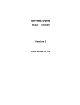
Install DP series oven(s) in a location with sufficient space and ventilation as specified as below.
2. Install on a level surface.
Install unit on a level and even surface. Failure to do so may result in abnormal vibrations or
noise, possibly causing complications and/or malfunction.
Approximate unit weight:
DP200: approx. 45kg, DP300: approx. 72kg, DP410: approx. 210kg, DP610: approx. 310kg.
Handle with care. Transportation and installation should always be done by two or more people.
Min. 20cm
Min. 20cm
Equipment
Door
DP200: Min. 40cm
DP300: Min. 50cm
DP410: Min. 65cm
DP610: Min. 80cm
Min. 20cm

5
2. PRE-OPERATION PROCEDURES
Installation Precautions & Procedures
3. Install in a safe location.
In the event of an earthquake or other unforeseen incident, equipment may unexpectedly shift or
fall, causing injury. Taking preventative steps to install unit in a safe location, away from room
access doors and out of other danger is strongly recommended.
4. Install in a well-ventilated area (DP200/300 only).
Install unit so that side panel heat vents (see “Unit Overview 1” on P.11 for location) are
unobstructed and allowed to sufficiently diffuse heat. Failure to do so may result in excessive
temperatures inside the unit control panel, causing possible degraded CPU board performance,
malfunction or fire. See installation specifications above.
5. Install in a dry location.
Install unit where it will be free from liquid spray and other moisture. Failure to do so may result
in control mechanisms becoming wet, causing malfunction, electrical shock and/or fire.
6. Install in a location free of flammables and explosives.
Never install near flammables or explosives. This unit is NOT fire or blast resistant. Simply
switching the main power switch (ELB) “ON” or “OFF” can produce a spark, which could relay
during operation, causing a fire or explosion when near flammable or explosive fluids, chemicals
or gases/fumes. See “List of Hazardous Substances” (P.58).
Explosives
Flammables

6
2. PRE-OPERATION PROCEDURES
Installation Precautions & Procedures
7. Connect to power supply.
Connect power cable to a suitable facility outlet or terminal, according to the following electrical
requirements.
Electrical requirements:
DP200 Single phase 100V AC 50/60Hz 7A
DP300 Single phase 100V AC 50/60Hz 11A
DP410 Single phase 200V AC 50/60Hz 11.5A
DP610 Single phase 200V AC 50/60Hz 16A
※Check the line voltage on outlet or terminal to be used and properly evaluate whether to utilize
a line being shared by other equipment. If the unit is not activated by turning on the main
power switch (ELB), take an appropriate course of action, such as connecting the unit to a
dedicated power source.
※Multiple power cables connected to a single outlet may cause unit input voltage to drop,
resulting in degraded heating and temperature control performance.
8. Handle power cable with care.
Never operate unit with power cable bundled or tangled; and do not modifiy, bend, forcibly twist
or pull on power cable. Doing so may cause fire and/or electrical shock.
Do not risk damage to power cable by positioning it under desks or chairs, or by pinching it
between objects. Doing so may cause fire and/or electrical shock.
Do not place power cable near kerosene/electric heaters or other heat-generating devices.
Doing so may cause power cable insulation to overheat, melt and/or catch fire, which may result
in electric shock.
Turn off main power switch (ELB) immediately and disconnect from facility terminal or outlet, if
power cable becomes partially severed or damaged in any way. Failure to do so may result in
fire or electric shock.
Contact a local dealer or Yamato sales office for information about replacing power cable if it is
damaged.
Always connect power cable to appropriate facility outlet or terminal.

7
2. PRE-OPERATION PROCEDURES
Installation Precautions & Procedures
9.(1) Ground wire MUST be connected properly (DP200/300 at 100V AC).
・ Ground wire must be connected to a proper grounding line or teminal in order to avoid
electrical shock.
・ Never connect ground wire to gas lines or water pipes.
・ Never connect ground wire to telephone grounding lines or lightening rods. Doing so may
result in fire or electric shock.
・ Never insert multiple plugs into a single outlet. Doing so may result in power cable
overheating, fire or drop in voltage.
Connect to grounded outlet.
Outlet with ground receptacle
When no grounding terminal is found:
●Grounding to Electrical Equipment Technical
Standards, Section 19, class D (Grounding
Resistance Max. 100Ω) is required in Japan.
Contact a local dealer, electrician, or Yamato
Sales office for location-specific electrical
requirements.
Use grounded adapter for ungrounded outlets.
Outlet with no ground receptacle
Ground adapter
●Insert grounded power plug into ground
adapter. Connect grounding wire (green) from
ground adapter to a ground terminal.
9.(2) Ground wire MUST be connected properly (DP410/610 220V AC).
・ Grounding to Electrical Equipment Technical Standards, Section 19, class D (Grounding
Resistance Max. 100Ω) is required in Japan where no grounding terminal is provided. Contact a
local dealer, electrician, or Yamato Sales office for location-specific electrical requirements.
・ Connect terminals securely to facility terminal or to an appropriate connector.
Plugs and connectors are not included with
this unit. Ground unit properly to facility
outlet or terminal as required.
Never connect ground wire to gas lines, water pipes, telephone grounding lines or lightening
rods. Doing so may result in fire or electrical shock.
10. Observe wire color designation when connecting to facility terminal (DP410/610
200V AC) See table below.
Confim that the facility main breaker is OFF before
connecting the round terminals from the power cable. No
power plugs or connectors of any kind are included with
DP410/610. Where required, purchase an appropriate
plug and properly connect using the round terminals.
Wire color
Terminal
Black
Live side
White
Neutral side
Green
Ground
Ungrounded outlet
100V AC only
Ground adapter
Grounded plug
Grounding wire
with Y-terminal
W
w
G
Grounded plug
3 (three) Round Terminals for M5 screws
Green (to grounding terminal)
Black (to facility terminal)
White (to facility terminal)
Grounding prong

8
2. PRE-OPERATION PROCEDURES
Installation Precautions & Procedures
11. DO NOT disassemble or modify.
Attempting to disassemble or modifiy this unit in any way may result in malfunction, fire or
electric shock.
12. Position adjustable leveling feet (DP410/DP610 only).
Position the 2 (two) adjustable leveling feet,
located on the undercarriage of DP410/610
units.
After unit is installed, position the adjustable
leveling feet using the following procedure:
① Rotate leveling feet down until unit stands
securely on the floor.
② Check for any gaps between the floor and
4 (four) contact points (e.g. the 2 ‘two’
front leveling feet and the 2 ‘two’ rear
casters).
③ Once unit is secure, tighten both leveling
feet stop nuts firmly against the topmost
nut, to prevent leveling feet from turning
under vibration.
①
③

9
2. PRE-OPERATION PROCEDURES
Vacuum System Information
Vacuum System Information
Vacuum pumps and vacuum line components (sold separately) for DP series ovens
(1) Vacuum pump models and vacuum line components (sold separately), required for DP series
ovens, are shown in Table 2.1. Select an appropriate vacuum pump and vacuum line components
(sold separately) using the table below. Note that an appropriate check valve must also be selected
for vacuum pumps (sold separately). Vacuum line components are also offered as options and
available upon request.
Table 2.1 Vacuum pump models and required line components (sold separately) for DP series ovens
Item
Model
(Pump
Connection
Port Size)
Manufacturer
or Supplier
Vacuum
Pump
Model
(sold
separately)
Effective
Pump
Displacement
(at 50/60Hz)
in litters/min.
Pump
Inlet
Size
Required vacuum line components
DP200/300
(Pump
connection port
:18mm)
Yamato
Science
PD53
*1
50/60
18 mm
・15 mm ID vacuum hose
Qty 1
PX52
*1
PD103
100/120
27 mm
・15 mm ID vacuum hose
・25 mm ID vacuum hose
・Reducing pipe(18/27)
A(Brass)/C(Stainless St.)
Qty 1
Qty 1
Qty 1
PD138
*1
135/162
PX137
*1
135/162
30 mm
DP410/610
(Pump
connection
port
:NW25
flange)
Yamato
Science
PD138
*1
135/162
27 mm
・25 mm ID vacuum hose
・Vacuum hose adapter
・Clamp (NE20/25)
・Center ring (NW25)
Qty 1
Qty 1
Qty 1
Qty 1
PD203
*1
200/240
PX137
135/162
30 mm
PX202
200/240
Adixen
M(T)2010
142/170
NW25
flange
・Flexible hose
・Clamp (NW20/25)
・Center ring (NW25)
Qty 1
Qty 2
Qty 2
M(T)2015
208/250
M(T)2010C
142/170
M(T)2015C
208/250
Kashiyama
NeoDry15E
250
NW25
flange
・Flexible hose
・Clamp (NW20/25)
・Center ring (NW25)
Qty 1
Qty 2
Qty2
【Note】
・ *1 These pump models can be fitted with components for the KF-style quick-coupling flange, as on
all Adixen pump models.
・ If an existing vacuum pump is to be connected to a new DP series unit, and their inlet sizes do not
match, use an appropriate reducing joint.
(2) Be sure to use the proper vacuum line components between vacuum pump (sold separately) and
DP series unit to prevent any vacuum leaks.
(3) If an existing pump cabinet is to be used for a new vacuum pump (sold separately) installation on
DP models 410/610, be sure to place the vacuum pump (sold separately) inside of the cabinet so
that the oil gauge faces front and can be easily viewed and regularly inspected.

10
2. PRE-OPERATION PROCEDURES
Vacuum System Information
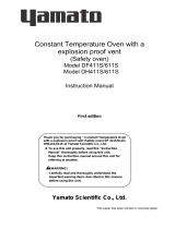
Vacuum System Information
Vacumm pump and vacuum line components (sold separately) for DP series ovens
φ18mm OD
DP200/DP300 pump connection port
Reducing joint
A(Brass) or C(Stailess St.)
Vacuum hose(φ15mm ID )
Vacuum hose (φ25mm ID)
DP410/610 pump connection port
NW25 flange
Clamp
Clamp
Center ring
Center ring
Vacuum hose adapter
Flexible hose
Vacuum hose (φ25mm ID)
Connection port sizeφ30mm, φ27mm
Connection port sizeφ30mm, φ27mm
Connection port size NW25 flange
Clamp
Center ring
Rotary Vacuum Pump
PD138/203, PX137/202 etc.
Rotary Vacuum Pump
KF25 quick-coupling specifications for M(T)2010/2015/2021,
PD/PX etc.
(Note)
components inside
broken line are
optional
Air-cooled Dry Vacuum Pump
NeoDry 15E

11
3. COMPONENT NAMES AND FUNCTIONS
Unit Overview 1
DP200/300 overview
Control Panel
Independent
Overheati
Prevention Device
Door Handle
Viewing Window
Vacuum Gauge
Pump Valve Knob
(closes with CW rotation)
Purge Valve Knob
(closes with CW rotation)
Caution-Rating
Spec. sticker
Heat Vents
Terminal Block Cover
(Terminal Block: option)
Main Power Switch (ELB)
Legs
Serial No. sticker
Door
Heat Vents
Pump Port
Purge Port
Power Cable w/plug

12
3. COMPONENT NAMES AND FUNCTIONS
Unit Overview 2
DP410/610 overview
Round Terminals
Purge Port
Pump Port
N2 Gas Inlet
(optional)
4(four) Casters
Safety Cover (DP610 only)
Door
Viewing Window
Flow Meter
(option)
Pump Valve Knob
(closes with CW rotation)
Purge Valve
(closes with CW rotation)
Vacuum Pump Cabinet Door
Vacuum Pump
(sold separately)
Pump slide tray (optional)
Caution-Rating sticker
Serial No. sticker
Door Handle
Independent
Overheat
Prevention Device
Vacuum Gauge
Control Panel
Main Power Switch
(ELB)
External Vacuum Pump Switch (optional)
Adjustable Leveling Feet (2 ‘two’ on undercarriage)
Digital Pirani Vacuum Gauge (optional)
Memory Recorder (option)
Terminal Block
(optional)
Power Cable
(Round terminals)

13
3. COMPONENT NAMES AND FUNCTIONS
Control Panel
No
Name
Description
1
Upper Display
Readout for temperature reading (current chamber temp), error codes, etc.
2
Lower Display
Readout for temperature setting, clock, timer, etc.
3
Function Indicator Lamps
Illuminates (one or more) to show which function is currently running or active
4
Mode Indicator Lamps
Illuminates (only one) to show which mode is currently running.
5
REMOTE Indicator Lamp
Illuminates while remote comm (optional item) transmission is in progress.
6
ERROR Indicator Lamp
Illuminates when an error occurs.
7
OPERATE Indicator Lamp
Illuminates during operation. Flashes in operation standby mode.
8
HEATER Indicator Lamp
Illuminates when heaters are receiving power.
9
EVENT Indicator Lamp
Illuminates when event output (optional item) is transmitted.
10
FIXED TEMP Indicator
Lamp
Illuminates during constant temperature operation.
11
PROGRAM Indicator Lamp
Illuminates during programmed operation. Flashes while entering program settings.
12
AUTO START Indicator
Lamp
Illuminate during auto start operation.
13
AUTO STOP Indicator
Lamp
Illuminates during auto stop operation.
14
MODE key
Press to switch between operation modes, ⑩~⑬ on control panel.
15
POWER key
Press and hold to switch between unit idle and unit standby.
16
DISP key
Press to switch between monitoring options in lower display.
17
START/STOP key
Press to start or stop an operation.
18
MENU key
Press to switch between setting options.
19
Esc key
Press to return to previous menu without finalizing settings.
20
▲(Up) key
Press to increase setting value.
21
▼(Down) key
Press to decrease setting value.
22
key
Press to move cursor left.
23
ENTER key
Press to finalize setting items.
24
Independent Overheat
Prevention Device
Set device to keep unit from exceeding a certain temperature.
24

14
4. OPERATION PROCEDURE
Prior Confirmation
(1) Power source and ground wire
Be sure to connect power cable to an appropriate power source and confirm that ground wire is
connected.
(2) Main power switch (ELB)
Turn ELB ON.
Test ELB function once a month or before extended operation. See “Maintenance Procedures”
(P.43) for details.
Check the lower display on the control panel when ELB is turned on and confirm it is showing
current time.
(3) Independent Overheat Prevention Device (IOPD)
Be sure to set IOPD temperature 20ºC over the chamber temperature setting.
Test IOPD function before each instance of extended operation. See “Maintenance Procedures”
(P.43) for details.
(4) Vacuum line connection
Be sure to connect unit securely to vacuum pump (sold separately).
(5) Vacuum pump (sold separately)
Check vacuum pump oil level and be sure it is free of contamination.
Decompression/Purge Procedure
(1) Decompressing unit chamber
1. Close purge valve.
2. Close the pump valve.
3. Turn vacuum pump ON.
4. Open the pump valve.
Note: open pump valve gradually when processing powdery or frothy test samples.
(2) Repressurizing unit chamber
1. Close pump valve.
2. Open purge valve to allow ambient pressure back into chamber.
3. Open Pump Valve.
4. Shut vacuum pump OFF.
Note: open purge valve gradually when processing powdery test samples.

15
4. OPERATION PROCEDURE
Setting Date & Time
The backup battery installed in DP series units, is a wear item and has an estimated life of
approximately 5 years. Replacing battery within the 5-year lifespan is recommended.
※ Contact a local dealer or Yamato sales office to request a replacement battery. If unit has
program data in memory, make a data backup file before replacing backup battery. See “Data
Backup” (P.35) in this section for details.
To set the current date & time,after replacing backup battery, follow the steps below.
1
Turn on power.
Turn ON the main power switch (ELB), located on the right
panel of the DP series units.
Lower display on the control panel will show the time.
This indicates that the machine is in “idle”.
Press and hold to display the standby screen.
Upper display shows current temperature in the chamber
while lower display shows current temperature setting.
This indicates that the machine is in “standby”.
2
Use the MENU key to view date
and time in displays
①
Press repeatedly until FUNC appears in lower
display, then press .
②
When [bUZZ] is shown in the lower display, press
to view the year in upper display, and month/date in
lower display.
is used to advance to
next item
is used to return to
previous item

16
4. OPERATION PROCEDURE
Setting Date & Time
3
Set the date.
Setting the year/month/date and clock.
①
Year and month/date are shown on upper and lower
displays respectively.
②
Press . Settable value begins flashing.
③
Set calendar year with and . Press .
④
Set month/date with and . Press .
※
Press to change digit (flashing) positions.
4
Set the time.
①
Press .
②
Press and set current time with and
press .
Set time in conformance to the 24-hour time system
(e.g. military time, continental time or railway time).
※
Press to change digit (flashing) positions.
③
Press twice to return to initial screen when
time/date settings are completed.
Keypad Tone Function
1
Set keypad tone.
①
Press repeatedly until FUNC is shown, then
press to bring up bUZZ in lower display. Press
. oFF begins flashing in upper display.
②
Select one of three keypad tone modes using
and press .
on: Activates tone for all keys. (factory default).
CLK: Activates tone for POWER and ENTER keys
only.
oFF: Deactivates tone for all keys.
Press the key twice to go back to initial screen
when keypad tone settings are completed.

17
4. OPERATION PROCEDURE
Mode and Function Flow

18
4. OPERATION PROCEDURE
Constant Temperature Mode
FIXED TEMP (constant temperature) mode runs DP series unit at a constant selected
temperature until START/STOP key is pressed, manually terminating operation.
SV: Set Value (temperature setting), t:Time
Setting constant temperature mode.
1
Turn on power.
Turn ON main power switch (ELB), located on right
panel of unit. (idle)
Press and hold to turn on power.
(standby)
Chamber temperature is shown in upper display,
Temperature setting is shown in lower display.
2
Select constant temperature mode.
Press repeatedly until FIXED TEMP indicator
lamp comes on.
※ Factory default temperatures are shown in upper
and lower displays on first-time start-up. All
subsequent start-ups will default to last temperature
values entered.
3
Set objective temperature.
①
Press . Changeable digits flash in lower
display.
②
Toggle between digits using and enter
desired value using .
Operating Temperature Range
:
DP200/300:40~240ºC (Setting range: 0~250ºC)
DP410/610: 40~20ºC (Setting range: 0~210ºC)
③
Press once temperature setting has been
entered.
Press once or twice to cancel setting.
SV
t
▲
Set temperature →START
▲
Press POWER key or
Press STOP key to terminate program.
/