Page is loading ...

Draw-Wire Displacement Sensors
Series WPS
Model MK120
Warnings
- Do not open the sensor housing.
- Do not let the measuring wire rewind without control (snap back).
- Avoid banging and knocking the sensor.
- Don‘ t let the power supply exceed the specified limits.
- Connect the power supply in accordance with the safety regulations for
electrical equipment.
- Fix the sensor with drawn in measuring wire to the target.
- Do not pull the measuring wire over range.
- Do not damage the measuring wire.
- Do not oil or grease the measuring wire.
- Do not bend the measuring wire.
- Do not pull the measuring wire at an angle.
- Do not allow to loop the measuring wire around objects.
- Do not loop the measuring wire around parts of the body.
Sensor Assembly
Mount the sensor through three screws M6. The sensor does not have
to be oriented in a special way. Choose the installation position so that
damage and soiling of the measuring wire is avoided. Prefer an installation
position with measuring wire outlet facing downwards if possible.
Assembly Instructions
wireSENSOR
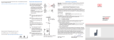
WPS- ... -MK120, measuring ranges 3000 and 5000 mm,
dimensions in mm (inches), not to scale
20.5
(.81)
53.1
(2.09)
107 (4.21)
107 (4.21)
120 (4.72)
120 (4.72)
27.5
(1.08)
73.5 (2.89)
130 (5.12)
ø58
(dia. 2.28)
(182 (7.16))
Mounting hole
3x ø6
(dia. .24)
120
(4.72)
107 (4.21)
107 (4.21) 27.5
(1.08)
120 (4.72) 73.5 (2.89)
220 (8.66)
272 (10.71)
53.1 (2.09) 20.5
(.81)
ø58
(dia. 2.28)
Mounting hole
3x ø6
(dia. .24)
WPS- ... -MK120, measuring ranges 7500 mm,
dimensions in mm (inches), not to scale
Wire Guide and Fastening
If the measuring wire has to be extracted from
the sensor to guide the wire resp. to fix it to the
target
- the sensor may not be held by another
person
- the measuring wire may not be further extract-
ed but only to the specified measuring range
- the surroundings of the sensor have to be
protected against snapping of the measuring
wire
Wire outlet 0 °
±3 ° tolerancy
max. 3 °
Fix the measuring wire to the target using a wire clip. Fed the measu-
ring wire perpendicularly from the sensor housing. Misalignment only
permissible up to 3 degrees. If you drag of the measuring wire on the
outlet hole or other objects, this leads for damaging and/or snapping of
the measuring wire. Keep measuring wire in an area where it cannot be
snagged or otherwise be violated.
Pin Assignment
Electrical Connection Output
-CR-Integral
cable
-SR- Connector
-U- Voltage
-P- Potentiometer
-I- Current
white
Female connector,
solder pin side
1 Power supply Power supply
brown 2 GND GND
green 3 Signal ---
yellow 4 GND ---
Use all potentiometers only in a voltage divider circuit. Using them as a
variable resistor, destroys the element. Ensure that the maximum current
through the viper is limited for sensors with hybrid potentiometer. Note the
pin assignment for draw-wire displacement sensors with encoder output
(E). The sensor contains an additional supplement for detailed information.
1
2
3
4
Declaration of incorporation
Declaration of incorporation according to the EC Machinery Directive
2006/42/EC, Annex II B
Manufacturer and authorized representative for the compilation of the rele-
vant technical documents
MICRO-EPSILON MESSTECHNIK GmbH & Co. KG
Königbacher Straße 15, 94496 Ortenburg / Germany
hereby declares that the machine designated below, as a result of its man-
ner of design, construction as well as version that has been placed on the
market - to the extent possible in the scope of delivery - corresponds to the
relevant, fundamental health and safety requirements of the EC Machinery
Directive, including the valid changes at the time of this declaration.
Model: wiresensor
Type designation: WDS-xxx, WPS-xxx
The following fundamental health and safety requirements in accordance
with Annex I of the above-named directive are applied and maintained:
- No. 1.1.2. Principles of safety integration
- No. 1.7.3. Marking of machinery
- No. 1.7.4. Instructions
Furthermore, the compliance with the following standards is explained,
including the valid changes at the time of this declaration:
- EN ISO 13857 Safety of machinery - Safety distances to prevent hazard
zones being reached by upper and lower limbs
- EN 60204-1: 2006/A1: 2009 Safety of machinery - Electrical equipment
of machines - Part 1: General requirements
- DIN EN 61326-1: 2013
- DIN EN 61326-2-3: 2013
Moreover, we declare that the relevant technical documentation for this
partly completed machinery has been created in accordance with part B of
Annex VII, and that we shall be obligated to deliver these upon the request
of the market surveillance authorities.
The described partly completed machinery is intended for installation in
a production line. The commissioning of this partly completed machinery
shall be prohibited until the partly completed machinery has been installed
in a machine that complies with the provision of the EC Machinery Directive
and for which an EC Declaration of Conformity in accordance with Annex II
A is available.
Ortenburg, October 8th 2015 Dr. Thomas Wisspeintner
Managing Director
/