THIS INSTRUCTION BOOKLET CONTAINS IMPORTANT
SAFETY INFORMATION.
PLEASE READ AND KEEP FOR FUTURE REFERENCE.
Whalen Furniture Mfg., Inc. Page 1 Factory No. 16086
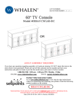
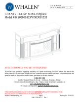
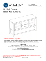
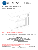
Laminate 44" High Console
Model # AVH-1
ADULT ASSEMBLY REQUIRED
If you have any questions regarding assembly or if you are missing parts, do not return this
item to the store where it was purchased. Please call our customer service number and have
your instructions and parts list ready to provide the model name, part name or factory number:
1-866-942-5362
Pacific Standard Time: 8:30 a.m. - 4:30 p.m., Monday - Friday
Or visit our web site 24 hours a day, 7 days a week for product assistance at
www.whalenstyle.com
Or e-mail your request to [email protected]
LOT NUMBER:
DATE PURCHASED: / /

Model # AVH-1
Please call for replacement parts or assistance: 1-866-942-5362
Whalen Furniture Mfg., Inc. Page 2 Factory No. 16086
MANUFACTURER: Whalen Furniture Mfg., Inc.
CATALOG: Laminate 44" High Console (AVH-1)
DATE OF MANUFACTURE: March 2014
MADE IN CHINA
How to adjust the European adjustable hinges on doors
Shipping may cause doors to go out of alignment. If you find that the doors need to be
adjusted slightly, turn the appropriate screw as illustrated below.
1. TO ADJUST DOOR FORWARD OR BACKWARD.
2. TO ADJUST DOOR TO RIGHT OR TO LEFT.
3. TO ADJUST DOOR UP OR DOWN.
MAXIMUM RECOMMENDED WEIGHT LOADS
MAXIMUM LOAD 50 lb. (22.7 kg)
FITS UP TO MOST 50” FLAT PANEL TVs
MAXIMUM LOAD 135 lb. (61.2 kg)
PLACE TV BEHIND STOPPER
THIS UNIT IS NOT INTENDED FOR USE WITH CRT TVS. USE ONLY WITH
FLAT PANEL TVS AND AUDIO/VIDEO EQUIPMENT MEETING RECOMMENDED SIZE AND
WEIGHT LIMITS. NEVER USE WITH LARGER/HEAVIER THAN RECOMMENDED FLAT PANEL
TVS OR EQUIPMENT. TO AVOID INSTABILITY, PLACE FLAT PANEL TV IN THE CENTRE OF
THE UNIT; DO NOT ALLOW TV TO OVERHANG UNIT IN ANY DIMENSION. IMPROPERLY
POSITIONED FLAT PANEL TVS, OR FLAT PANEL TVS OR OTHER EQUIPMENT THAT EXCEED
RECOMMENDED SIZE AND WEIGHT LIMITS COULD FALL OFF OR BREAK THE UNIT,
CAUSING POSSIBLE SERIOUS INJURY.

Model # AVH-1
Please call for replacement parts or assistance: 1-866-942-5362
Whalen Furniture Mfg., Inc. Page 3 Factory No. 16086
Important
Before you begin: Open, identify and count all parts prior to assembly. Lay out parts on a flat
and non-abrasive surface. You will need the parts identified on page 4 & 5 of this instruction
manual.
NOTE: IT IS VERY IMPORTANT TO USE GLUE WITH DOWELS. EXCESS GLUE CAN
BE WIPED OFF WITH DAMP CLOTH.
Insert Dowels at least half way by tapping lightly with a rubber mallet, IF NECESSARY.
CAM LOCK SYSTEM OPERATION
HOW THE KNOCK DOWN (KD) ASSEMBLY SYSTEM WORKS
1. Screw the Cam Bolt into the threaded insert on the panel.
2. Insert the Cam Lock into the pre-drilled hole on the panel.
3. Make sure the Cam Lock pointed arrow is pointed towards the entry of the Cam Bolt.
4. Connect both panels together; making sure Cam Bolt goes into pre-drilled hole on the
end of panel with Cam Lock.
5. Once the Cam Bolt is connected inside the Cam Lock, take a Phillips screwdriver and
tighten the Cam Lock clockwise.
You are now ready to assemble the KD unit.

Model # AVH-1
Please call for replacement parts or assistance: 1-866-942-5362
Whalen Furniture Mfg., Inc. Page 4 Factory No. 16086
Parts and Hardware List
Please read completely through the instructions and verify that all listed parts and hardware are
present before beginning assembly.
A- Top Panel (1) B- Left Side Panel (1)
C- Right Side Panel (1) D- Bottom Panel (1)
E- Front Upper Stretcher (1) F- Front Bottom Stretcher (1) G- Back Bottom Stretcher (1)
H- Divider Panel (1) I- Adjustable Shelf (2)
J- Center Support (1) K- Back Panel (2)
L- Left Door (1) M- Right Door (1)

Model # AVH-1
Please call for replacement parts or assistance: 1-866-942-5362
Whalen Furniture Mfg., Inc. Page 5 Factory No. 16086
Parts and Hardware List
Please read completely through the instructions and verify that all listed parts and hardware are
present before beginning assembly.
(1) Cam Lock (2) Cam Bolt (3) Wood Dowel
(22+1 extra) (22+1 extra) (21+1 extra)
(4) 3/4” Bolt (5) 2” Wood Screw (6) 3/4” Ring Shank Screw
(4+1 extra) (6+1 extra) (24+1 extra)
(7) #5 x 5/8” Wood Screw (8) Magnetic Catch (9) Shelf Pin
(4+1 extra) (2) (8+1 extra)
(10) Knob w/Bolt (2) (11) Cable Control (2) (12) Glue (1)
Touch-up Pen (1) Tipping Restraint Hardware Kit (2)
(Inside Plastic Bag)
Tools required: Phillips screwdriver, Rubber Mallet, and Hammer (not provided).

Model # AVH-1
Please call for replacement parts or assistance: 1-866-942-5362
Whalen Furniture Mfg., Inc. Page 6 Factory No. 16086
Assembly Instructions
NOTE: Please do not fully tighten all bolts and screws until you finish assembling all parts.
Once assembled, go back and fully tighten all bolts and screws. This will make the assembly
easy.
1. Unpack the unit and confirm that you have all the hardware and required parts.
2. Place the Top Panel (A), Left & Right Side Panels (B & C), Bottom Panel (D) and Front
Bottom Stretcher (F) on a level and protective surface with the holes facing up. Securely
screw the Cam Bolts (2) into the designated small holes, as shown in detail #1. Make sure
the Cam Bolts are screwed straightly. Fully tighten with Phillips screwdriver.
Hardware required Sketch Qty.
(2) Cam Bolt (22)
Tools required: Phillips screwdriver

Model # AVH-1
Please call for replacement parts or assistance: 1-866-942-5362
Whalen Furniture Mfg., Inc. Page 7 Factory No. 16086
Assembly Instructions
3. Using the pilot holes as a guide, attach 2 Magnetic Catches (8) to both sides of the Divider
Panel (H) with four 5/8” Wood Screws (7). Tighten the screws with a Phillips screwdriver.
Make certain the magnetic plates point towards the front of the unit. See detail #2.
4. Insert 2 Wood Dowels (3) into the large holes pre-drilled on the bottom edge of Divider
Panel (H) as a guide. Tap in with a rubber mallet, if necessary. Make sure that you use a
small amount of glue on both ends of all dowels.
5. Align and attach the Divider Panel (H) to the Bottom Panel (D) using two 2” Wood Screws (5)
as shown in detail #2A. Make sure the magnetic plates face the front of the unit (the side
with cutouts is front). Securely tighten with a Phillips screwdriver.
6. Tightly screw the Center Support (J) into the threaded insert on the Bottom Panel (D). See
detail #2A.
Hardware required Sketch Qty.
(3) Wood Dowel (2)
(5) 2” Wood Screw (2)
(7) 5/8” Wood Screw (4)
(8) Magnet Catch (2)
Tools
r
e
q
uire
d
: Phillips screwdriver

Model # AVH-1
Please call for replacement parts or assistance: 1-866-942-5362
Whalen Furniture Mfg., Inc. Page 8 Factory No. 16086
Assembly Instructions
7. Insert 2 Wood Dowels (3) into the front end holes and 3 Cam Locks (1) into the side holes of
the Bottom Panel (D). DO NOT put dowels in the Cam Bolt holes. Make sure the pointed
arrow on the Cam Lock is facing out and pointing towards the entry of Cam Bolt.
8. Align and attach Front Bottom Stretcher (F) to the Bottom Panel (D) making sure the top
edges are flush with each other. Once the Cam Bolt is connected inside the Cam Lock, turn
the Cam Locks clockwise until they are tight. See detail #3.
9. Pick up Back Bottom Stretcher (G) and attach to the Bottom Panel (D) by using one Cam
Lock (1) and 2 Wood Dowels (3). Make sure the Cam Lock face inward. See detail #3.
*It is very important to use a small amount of glue on both ends of dowels.
Hardware required Sketch Qty.
(1) Cam Lock (4)
(3) Wood Dowel (4)
Tools required: Phillips screwdriver

Model # AVH-1
Please call for replacement parts or assistance: 1-866-942-5362
Whalen Furniture Mfg., Inc. Page 9 Factory No. 16086
Assembly Instructions
10. Insert 3 Wood Dowels (3) into the end holes and 4 Cam Locks (1) into the side holes on the
right of assembled base as shown in detail #4. Make sure the Cam Locks are oriented
properly.
11. Align and attach the Right Side Panel (C) to the Base by engaging all the Cam Locks (1)
(Refer to page #3 on Cam lock system operation supplement). See detail #4.
12. Attach Front Upper Stretcher (E) to the Right Side Panel (C) using a Cam Lock (1). Make
sure the Cam Lock points towards inside of unit. As shown in detail #4A.
13. Repeat the same process to attach the Left Side Panel (B).
14. Now, secure the Bottom Panel (D) to the Side Panels (B & C) by inserting and screwing four
2” Wood Screws (5) into the drilled holes at front side of the Bottom Panel. Securely tighten
with a Phillips screwdriver. See detail #4.

Model # AVH-1
Please call for replacement parts or assistance: 1-866-942-5362
Whalen Furniture Mfg., Inc. Page 10 Factory No. 16086
Assembly Instructions
15. Stand the unit upright.
16. Insert 9 Wood Dowels (3) into the top holes and 8 Cam Locks (1) into the side holes of the
last assembly. As shown in detail #5. DO NOT put dowels in the Cam Bolt holes.
17. Ask for assistance to position the Top Panel (A) in place. Make sure that all Cam Bolts are
connected inside Cam Locks simultaneously. Tighten all Cam Locks clockwise with a
Phillips screwdriver. See detail #5.
Hardware required Sketch Qty.
(1) Cam Lock (8)
(3) Wood Dowel (9)
Tools required: Phillips screwdriver

Model # AVH-1
Please call for replacement parts or assistance: 1-866-942-5362
Whalen Furniture Mfg., Inc. Page 11 Factory No. 16086
Assembly Instructions
18. Now, go back and tighten all cam locks and screws. Make sure that all the parts are tight
and there are no gaps between the parts. This will help keep the unit square.
19. Using the pilot holes on the back edge of Top Panel (A) for easy alignment, lay and attach 2
Back Panels (K) in place using the 3/4” Ring Shank Screws (6), as shown in detail #6.
20. Now, attach 2 Cable Controls (11) to the Divider Panel (H) using the 3/4” Bolts (4) provided.
Securely tighten with a Phillips screwdriver. See detail #6.
21. The Cable Controls (11) allow you to organize, route and separate your component cords
and cables to minimize tangling and signal interference. As shown in detail #6.
Hardware required Sketch Qty.
(4) 3/4” Bolt (4)
(6) 3/4” Ring Shank Screw (24)
(11) Cable Control (2)
Tools required: Phillips screwdriver, Rubber Mallet and Hammer

Model # AVH-1
Please call for replacement parts or assistance: 1-866-942-5362
Whalen Furniture Mfg., Inc. Page 12 Factory No. 16086
Assembly Instructions
22. Stand the unit upright.
23. Tilt and install the Adjustable Shelves (I) with the provided Shelf Pins (9) at the desired height,
as shown in detail #7. Make sure that the cutout of Shelf snugly fits the side panel posts.
24. Extend the Hinge Arms pre-attached on Right Door (M) and attach to the Hinge Bases on the
Right Side Panel (C). Align and insert the “U” slot on Hinge Arm under the bolt head on the
Hinge Base. Make sure that both door hinges engage and function properly. See detail #7A.
25. Close the door to double check the alignment. If you find that the doors need to be adjusted
slightly, please refer to the supplement on page #2 and turn the appropriate screws for a
perfectly aligned door. After adjusted, lock the hinges in place by tighten the bolt on Hinge Base.
See detail #7A.
26. Repeat the same procedure to install the Left Door (L) to the Left Side Panel (B).
27. Attach the Knobs (10) at front side of Left & Right Doors (L & M) with the provided Knob Bolts,
as shown in detail #7A.
Hardware required Sketch Qty.
(9) Shelf Pin (8)
(10) Knob and Bolt (2)
Tools required: Phillips screwdriver

Model # AVH-1
Please call for replacement parts or assistance: 1-866-942-5362
Whalen Furniture Mfg., Inc. Page 13 Factory No. 16086
Assembly Instructions
28. In case of uneven floor, Floor Levelers are provided at the bottom of the unit for the necessary
adjustment. To adjust unit in case of tilting or doors not being level, simply tilt the unit back and
raise or lower floor leveler by hand to correct tilting and/or level doors. As shown in detail #8.
TIPPING RESTRAINT HARDWARE
Note: We have included two sets of Tipping Restraint Hardware for this unit. You must
install this hardware to prevent accidents or injuries from falling unit.
When properly installed, this restraint can provide protection against the unexpected tipping
of the unit due to small tremors, bumps or climbing. We strongly recommend mounting this
hardware to a wall stud and your unit.
Please carefully read the instructions printed on the plastic bag containing the tip-over restraints.
You must install the Tipping Restraint Hardware with the unit in use to prevent any
accidents or damage to the unit. Use of Tipping Restraints may only reduce, but not
eliminate, the risk of tip-over.
Tools required: Phillips screwdriver, Mallet, Power Drill, and 3/8” Drill Bit.

Model # AVH-1
Please call for replacement parts or assistance: 1-866-942-5362
Whalen Furniture Mfg., Inc. Page 14 Factory No. 16086
QUALITY GUARANTEE
We are confident that you will be delighted with your Whalen Furniture purchase.
Should this product be defective in workmanship or materials or fail under normal use,
we will repair or replace it for up to one (1) year from date of purchase. Every Whalen
Furniture product is designed to meet your highest expectations. We guarantee that you
will immediately see the value of our fine furniture.
This warranty gives you specific legal rights and you may also have other rights which
vary from State to State.
Customer Service: 1-866-942-5362
8:30 a.m. - 4:30 p.m., PST, Monday to Friday
www.whalenstyle.com
Care and Maintenance
Use a soft, clean cloth that will not scratch the surface when dusting.
Use of furniture polish is not necessary. Should you choose to use polish, test first in an
inconspicuous area.
Using solvents of any kind on your furniture may damage the finish.
Never use water to clean your furniture as it may cause damage to the finish.
Always use coasters under beverage glasses and flowerpots.
Liquid spills should be removed immediately. Using a soft clean cloth, blot the spill gently.
Avoid rubbing.
Always use protective pads under hot dishes and plates. Heat can cause chemical changes
that may create spotting within the furniture finish.
Stains or marks from crayons or ink markers will be difficult to remove.
In the event that your furniture is stained or otherwise damaged during use, we recommend
that you call a professional to repair your furniture.
Check bolts/screws and nuts periodically and tighten them if necessary.
Further advice about wood furniture care
It is best to keep your furniture in a climate-controlled environment. Extreme temperature and
humidity changes can cause fading, warping, shrinking and splitting of wood. It is advised to keep
furniture away from direct sunlight as sun may damage the finish.
Proper care and cleaning at home will extend the life of your purchase. Following these important
and helpful tips will enhance your furniture as it ages.
A Touch-up Pen has been provided to repair any small nicks or scratches that may occur during
assembly or shipping.
We hope you enjoy your purchase for many years.
Thank you for your purchase.

*AVH-1-1-TP Top Panel *AVH-1-16-KB Knob w/Bolt
*AVH-1-2-LSP Left Side Panel *AVH-1-17-CC Cable Control
*AVH-1-3-RSP Right Side Panel *AVH-1-18-CL Cam Lock
*AVH-1-4-AS Adjustable Shelf *AVH-1-19-CB Cam Bolt
*AVH-1-5-BP Bottom Panel *AVH-1-20-3/4B 3/4" Bolt
*AVH-1-6-DP Divider Panel *AVH-1-21-2WS 2" Wood Screw
*AVH-1-7-LD Left Door complete *AVH-1-22-3/4RSS 3/4" Ring Shank Screw
*AVH-1-8-RD Right Door complete *AVH-1-23-5/8S 5/8" Screw
*AVH-1-9-DHS Door Hinge w/Screw *AVH-1-24-SP Shelf Pin
*AVH-1-10-MC Magnetic Catches *AVH-1-25-WD Wood Dowel
*AVH-1-11-BP Back Panel *AVH-1-26-G Glue
*AVH-1-12-FUS Front Upper Stretcher *AVH-1-27-TUP Touch-up Pen
*AVH-1-13-FBS Front Bottom Stretcher *AVH-1-28-TRHK Tipping Restraint Hardware Kit
*AVH-1-14-BBS Back Bottom Stretcher *AVH-1-29-CH Complete Hardware
*AVH-1-15-CS Center Support
IF YOU NEED TO REQUEST ANY PARTS PLEASE USE THE LIST BELOW
Laminate 44" High Console (AVH-1)
/