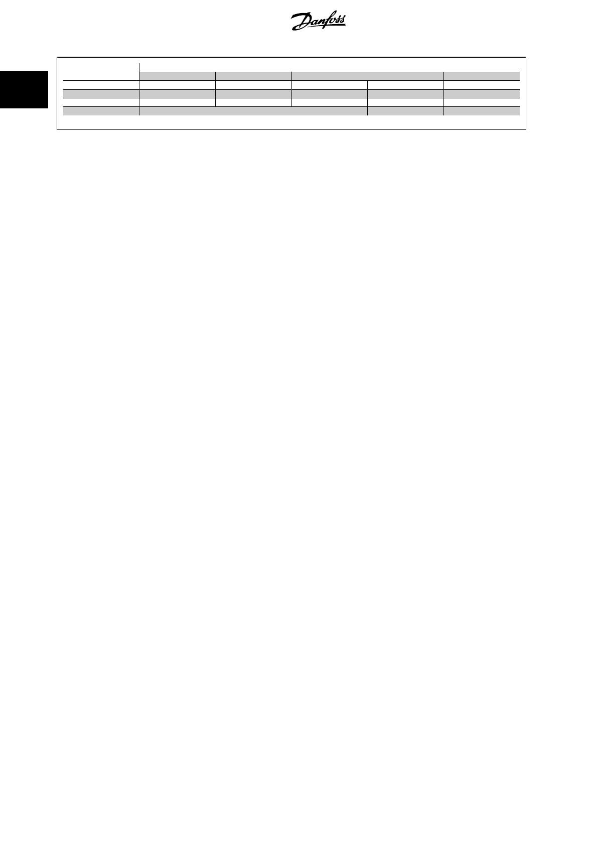
Danfoss VLT HVAC Drive FC 102 Operating instructions

Category
Networking
Type
Operating instructions

This manual is also suitable for

Contents
1 Introduction
3
Safety 3
Introduction 4
About this Manual 4
Assumptions 4
HP/kW Conversion 6
2 VLT Functional Features
7
Drive Operation (03-14) 7
Motor and Drive Thermal Protection (15, 16, 18) 7
Set-up 1-4 and Day/Night operation (17, 29) 7
Current Monitoring and Limits (19) 7
Direction of Rotation (21-22) 7
Start/Stop (23) 7
Freeze Mode (25, 26) 8
Coast (27, 28) 8
Motor Ramp-up and Ramp-down Rate (31, 32) 8
Hand/Auto Modes (34) 8
Run Enable (35) 8
Bus Functions (36, 37) 8
Jog Frequency and Command (38, 39) 8
Relay Out 1, 2 (40, 41, 43, 44) 8
PID Control Functions (61-65) 8
Sleep Mode (59) 9
Terminals 53, 54, (87-88) 9
Warnings and Alarms (90-94) 9
Error Status (99) 9
3 VLT Network Strategies
11
Strategy One 11
Strategy Two 11
Strategy Three 12
Strategy Four 12
4 VLT Special Functions
15
Special Functions 15
Analog Input Monitoring 15
Drive Relay Control 15
5 Network Connection
17
VLT
®
HVAC Drive FLN Operating Instructions Contents
MG.11.Z1.02 - VLT is a registered Danfoss trademark
1
6 Parameters
19
Parameter Settings 19
7 Start-up and Troubleshooting
21
Start-up 21
Start-up of FLN Control 21
Troubleshooting 21
Faults, Warnings and Alarms 21
Alarms and warnings 21
Start-up 30
Start-up of FLN Control 30
Index
31
Contents VLT
®
HVAC Drive FLN Operating Instructions
2
MG.11.Z1.02 - VLT is a registered Danfoss trademark
1Introduction
1.1.1 Safety
Rotating shafts and electrical equipment can be hazardous. Therefore, it is strongly recommended that all electrical work conform to
National Electrical Code (NEC) and all local regulations. Installation, start-up and maintenance should be performed only by qualified
personnel.
Factory recommended procedures, included in this manual, should be followed. Always disconnect electrical power before working on the unit. Although
shaft couplings or belt drives are generally not furnished by the manufacturer, rotating shafts, couplings and belts must be protected with securely
mounted metal guards that are of sufficient thickness to provide protection against flying particles such as keys, bolts and coupling parts. Even when the
motor is stopped, it should be considered “alive” as long as its controller is energized. Automatic circuits may start the motor at any time. Keep hands
away from the output shaft until the motor has completely stopped and power is disconnected from the controller.
Motor control equipment and electronic controls are connected to hazardous line voltages. When servicing drives and electronic controls, there will be
exposed components at or above line potential. Extreme care should be taken to protect against shock. Stand on an insulating pad and make it a habit
to use only one hand when checking components. Always work with another person in case of an emergency. Disconnect power whenever possible to
check controls or to perform maintenance. Be sure equipment is properly grounded. Wear safety glasses whenever working on electric control or rotating
equipment.
Safety Guidelines
1. The drive must be disconnected from the AC line before any service work is done.
2. The “Stop/Off” key on the of the drive does not disconnect the equipment from the AC line and is not to be used as a safety switch.
3. Correct protective grounding of the equipment must be established. The user must be protected against supply voltage and the motor must be
protected against overload in accordance with applicable national and local regulations.
4. Ground currents are higher than 3 mA.
Warning against Unintended Start
1. While the drive is connected to the AC line, the motor can be brought to a stop by means of external switch closures, serial bus commands or
references. If personal safety considerations make it necessary to ensure that no unintended start occurs, these stops are not sufficient.
2. During programming of parameters, the motor may start. Be certain that no one is in the area of the motor or driven equipment when changing
parameters.
3. A motor that has been stopped may start unexpectedly if faults occur in the electronics of the drive, or if an overload, a fault in the supply AC
line or a fault in the motor connection or other fault clears.
4. If the “Local/Hand” key is activated, the motor can only be brought to a stop by means of the “Stop/Off” key or an external safety interlock
NB!
It is responsibility of user or person installing drive to provide proper grounding and branch circuit protection for incoming power and
motor overload according to National Electrical Code (NEC) and local codes.
The Electronic Thermal Relay (ETR) in UL listed VLTs provides Class 20 motor overload protection in accordance with NEC in single motor applications,
when par. 1-90
Motor Thermal Protection
is set for ETR TRIP 1, ETR TRIP 2, ETR TRIP 3, or ETR TRIP 4, and par. 1-24
Motor Current
is set for rated
motor (nameplate) current.
1.1.2 Caution
Caution
The frequency converter DC link capacitors remain charged after power has been disconnected. To avoid an electrical shock hazard, disconnect the
frequency converter from the mains before carrying out maintenance. Wait at least as follows before doing service on the frequency converter:
VLT
®
HVAC Drive FLN Operating Instructions 1 Introduction
MG.11.Z1.02 - VLT is a registered Danfoss trademark
3
1
Voltage
Minimum Waiting Time
4 min. 15 min. 20 min. 30 min. 40 min.
200 - 240 V 1.1 - 3.7 kW 5.5 - 45 kW
380 - 480 V 1.1 - 7.5 kW 11 - 90 kW 110 -200 kW 250 - 450 kW
525 - 600 V 1.1 - 7.5 kW 110 - 250 kW 315 - 560 kW
525 - 690 V 45 - 90 kW 110 - 250 kW 315 - 560 kW 630 - 1200 kW
Be aware that there may be high voltage on the DC link even when the LEDs are turned off.
1.2.1 Introduction
The Siemens Floor Level Network (FLN) is a master/ slave control network for serial communication with various control devices. The FLN controller is
RS-485 compatible, half duplex, with an operating rate of 4800 or 9600 baud. Recommended wiring is shielded, twisted pair. The FLN software protocol
is designed to be general in nature to accommodate any unique properties of each device type. The node address system allows up to 96 devices to be
used on any one system.
The VLT is a programmable frequency converter, which controls the operation of 3-phase, standard induction electrical motors in the HVAC industry.
The VLT control card has FLN communication protocol software built-in. The drive uses optical isolation for fault tolerance and noise immunity.
The FLN communicates directly with the VLT drive via the RS-485 serial interface bus. In addition to being able to control the drive, most drive configuration
and control parameters can be reviewed and changed through the FLN. Also, the operational status of the drive can be read and monitored through the
bus. Diagnostic and operational information stored in the VLT is easily available, such as kWh of energy used, total operation hours, drive status, motor
speed, and many other useful items which can be accessed and monitored through the FLN.
The FLN is designed to communicate with any controller node that supports the interfaces defined in this document.
1.2.2 About this Manual
The documentation in this manual provides comprehensive information on the connection, programming, and startup of the VLT for use with the FLN. It
is intended as both an instruction and reference manual. Functions and features of the VLT frequency converter are also briefly reviewed to serve as a
guideline to optimize your communication system. Read this manual before programming since important information is provided in each section. For
detailed information on using the VLT, see the Operating Instructions.
1.2.3 Assumptions
This manual assumes that the controller node supports the interfaces in this document and that all the requirements and limitations stipulated in the
controller node and the VLT are strictly observed. It is assumed that the user understands the general capabilities and limitation of the controller node
and the VLT Frequency Converter.
1.2.4 Available literature for
- Operating Instructions MG.11.Ax.yy provide the neccessary information for getting the frequency converter up and running.
- Design Guide MG.11.Bx.yy entails all technical information about the frequency converter and customer design and applications.
- Programming Guide MG.11.Cx.yy provides information on how to programme and includes complete parameter descriptions.
- Mounting Instruction, Analog I/O Option MCB109, MI.38.Bx.yy
-
PC-based Configuration Tool MCT 10, MG.10.Ax.yy enables the user to configure the frequency converter from a Windows
based PC environ-
ment.
-
VLT
®
Energy Box software at
www.danfoss.com/BusinessAreas/DrivesSolutions
then choose PC Software Download
-
VLT
®
Drive Applications, MG.11.Tx.yy
- Operating Instructions BACnet, MG.11.Dx.yy
- Operating Instructions Profibus, MG.33.Cx.yy.
- Operating Instructions Device Net, MG.33.Dx.yy
- Operating Instructions LonWorks, MG.11.Ex.yy
1 Introduction VLT
®
HVAC Drive FLN Operating Instructions
4
MG.11.Z1.02 - VLT is a registered Danfoss trademark
1
- Operating Instructions High Power, MG.11.Fx.yy
- Operating Instructions Metasys, MG.11.Gx.yy
- Operating Instructions FLN, MG.11.Zx.yy
x = Revision number
yy = Language code
technical literature is available in print from your local Sales Office or online at:
www.danfoss.com/BusinessAreas/DrivesSolutions/Documentations/Technical+Documentation.htm
VLT
®
HVAC Drive FLN Operating Instructions 1 Introduction
MG.11.Z1.02 - VLT is a registered Danfoss trademark
5
1
1.2.5 Abbreviations and Standards
Abbreviations: Terms: SI-units: I-P units:
a Acceleration
m/s
2
ft/s
2
AWG American wire gauge
Auto Tune Automatic Motor Tuning
°CCelsius
I Current A Amp
I
LIM
Current limit
Joule Energy J = Nm ft-lb, Btu
°F
Fahrenheit
FC Frequency Converter
f Frequency Hz Hz
kHz Kilohertz kHz kHz
Local Control Panel
mA Milliampere
ms Millisecond
min Minute
MCT Motion Control Tool
M-TYPE Motor Type Dependent
Nm Newton Metres in-lbs
I
M,N
Nominal motor current
f
M,N
Nominal motor frequency
P
M,N
Nominal motor power
U
M,N
Nominal motor voltage
par. Parameter
PELV Protective Extra Low Voltage
Watt Power W Btu/hr, hp
Pascal Pressure Pa = N/m² psi, psf, ft of water
I
INV
Rated Inverter Output Current
RPM Revolutions Per Minute
SR Size Related
T Temperature C F
t Time s s,hr
T
LIM
Torque limit
U Voltage V V
Table 1.1: Abbreviation and Standards table .
1.2.6 HP/kW Conversion
A conversion index for determining kW and HP ratings is shown below.
kW HP
kW HP
0.25 0.33 45 60
0.37 0.5
55 75
0.55 0.75 75 100
0.75 1.0
90 125
1.1 1.5 110 150
1.5 2.0
132 175
2.2 3.0 160 200
3.0 -
200 300
4.0 5.0 250 -
5.5 7.5
300 -
7.5 10 315 350
11 15
355 450
15 20 400 500
18.5 25
450 600
22 30
30 40
37 50
1 Introduction VLT
®
HVAC Drive FLN Operating Instructions
6
MG.11.Z1.02 - VLT is a registered Danfoss trademark
1
2 VLT Functional Features
The FLN protocol built into the VLT frequency converter allows programming of numerous features and monitoring of the drive via the serial bus and the
standard RS-485 port. The VLT also has the capability to control closed or open loop systems on its own and has been designed specifically for HVAC
applications. Always accessible in real-time are the system status, what the motor and drive are doing, and if there are any problems. The VLT continuously
monitors all aspects of motor and drive status and issues alarms or warnings for adverse conditions. The FLN interacts with the drive based upon a point
map database and the selected interface strategy. Many, but not all, drive features are accessible through the point map. See the
Operating Instruc-
tions
for more drive details. Table
Point Mapping
lists the map points and Table
Point database definitions
supplies definitions. Below is a review of some
frequently used drive features and the associated point map numbers.
2.1.1 Drive Operation (03-14)
These points provide the FLN with operational status information such as output frequency, motor current, output voltage, power and energy. The run
time in hours that power has been supplied to the motor is also stored for display, along with cumulative energy used in kWh.
2.1.2 Motor and Drive Thermal Protection (15, 16, 18)
The motor and drive are protected against thermal overload. The percentage of thermal load is displayed. Point 18 indicates if either the motor or drive
thermal limit has been exceeded.
2.1.3 Set-up 1-4 and Day/Night operation (17, 29)
In the FLN system it is not recommended to operate in multible set-up. The drive should remain in Set-up 1 at all times.
The drive is capable of maintaining four independent program set-ups. Each set-up supports independent point map configurations. Seasonal changes,
various acceleration or deceleration rates, or other operation modes can be accommodated. Point 17 indicates which setup is active. The set-up change
is programmed through the drive’s keypad or digital I/Os. Day/night operation is implemented in the point map (29).
2.1.4 Current Monitoring and Limits (19)
The maximum current that the drive provides to the motor can be limited. This tends to limit the torque that can be produced by the motor. Data point
19 indicates if the motor is operating at that current limit.
2.1.5 Direction of Rotation (21-22)
The drive responds to serial commands to reverse direction of the motor. The drive can safely reverse motor rotation while in operation. Many applications
benefit from this ability, such as vane axial fans reversed for smoke extraction or cooling towers for deicing. par. 8-54
Reversing Select
, must be set to
serial communication for point 22 to command the feature.
2.1.6 Start/Stop (23)
To run the drive from the FLN or in Auto mode from the drive‘s digital control terminals, a start command must be given at data point 23. When a stop
command is given at this point, the drive will only run in Hand mode.
2.1.7 Ramp Select (24)
Datapoint 24 selects the active ramp.
VLT
®
HVAC Drive FLN Operating Instructions 2 VLT Functional Features
MG.11.Z1.02 - VLT is a registered Danfoss trademark
7
2
2.1.8 Freeze Mode (25, 26)
If desired, the frequency of the drive can be frozen at its present value. The mode is indicated by data point 25. It is an option available when serial
interface is lost.
2.1.9 Coast (27, 28)
The coast command (28) shuts down the inverter and makes the motor freewheeling, which normally brings it to stand still. The drive cannot be restarted
in any mode before the coast command is removed. It is, therefore, often used as a safety interlock. Data point 27 indicates when the drive is coasted.
2.1.10 Motor Ramp-up and Ramp-down Rate (31, 32)
The time to accelerate or decelerate the drive between 0 Hz and the motor’s nominal frequency can be programmed. The drive is capable of settings
between one to 3600 seconds (one hour). Only Ramp1 is accessible from the FLN network.
2.1.11 Hand/Auto Modes (34)
The
SEL HND.AUTO
shows which mode the drive is in. The drive can be commanded into either
Hand
or
Auto
mode by pressing the respective keys on
the keypad of the drive. Hand mode disables any programmed control strategies and allows the drive keypad to be used to set the drive speed. The only
serial communication command that can override Hand mode is data point 28,
CMD COAST
.
2.1.12 Run Enable (35)
Set data point 35 to
ON
to run the drive from the FLN with default drive parameter settings. In the
OFF
mode, the drive will run only in Hand mode or
in Auto mode from the drive‘s digital control terminals. par. 8-53
Start Select
, controls the interaction of point 35 and the digital run command.
2.1.13 Bus Functions (36, 37)
The amount of time the drive will wait between communication packets is programmable. If the time is exceeded, the drive will assume serial commu-
nication has stopped and respond with programmable choices. The drive can ignore the loss, freeze its current output, stop, run at a predetermined jog
frequency, run at maximum output frequency or stop and trip while issuing an alarm. Wait time is selected at point 36 and the function after a timeout
at point 37. See descriptions for par. 5-65
Pulse Output Max Freq #29
and par. 5-66
Terminal X30/6 Pulse Output Variable
in the
Programming Guide
.
2.1.14 Jog Frequency and Command (38, 39)
The Jog Frequency can be set by data point 38. Setting data point 39 to [On] will cause the frequency converter to send the Jog Frequency to the motor.
2.1.15 Relay Out 1, 2 (40, 41, 43, 44)
Two programmable relay outputs (Form C, 240 VAC, 2 Amp) are available. These can be triggered through the serial bus by command points 40 and 41.
This allows the FLN to utilize the drive’s built-in relays as additional network programmable relays. The data points 43 and 44 indicate whether the relay
is triggered or not (On/Off). Parameters 5-40.0 and 5-40.1,
Function Relay 1
and
Function Relay 2
, must be set to [45] Bus controlled, [46] Bus controlled
1, if timeout or [47] Bus controlled 0, if timeout.
2.1.16 PID Control Functions (61-65)
The VLT has a sophisticated built-in proportional, integral, derivative (PID) controller. The PID controller is activated by setting par. 1-00
Configuration
Mode
, to Closed loop through the drive’s keypad.
2 VLT Functional Features VLT
®
HVAC Drive FLN Operating Instructions
8
MG.11.Z1.02 - VLT is a registered Danfoss trademark
2
The PID controller in the VLT supports two feedback values and two setpoints. The feedback can be received in the form of network bus signals and/or
standard 0-10 V transmitters. The 2 set-point controller is capable of controlling return fans based on a fixed differential flow, secondary pumping systems,
and so on. This can be used to supplement the BMS system to save on points or capacity. For details on use of the two feedback/setpoint feature, refer
to the
Operating Instructions
. Data points 43 and 44 show the status of an FLN command to the drive.
The points PI GAIN and PI TIME are gain parameters similar to the P and I gains in the FLN TECs. The PI loop is structured differently than the Siemens
loop, so there is not a one-to-one correspondence between the gains. The following formulas allow translation between and Siemens gains.
Converting from PI gains to Siemens P and I gains:
P
Gain
SIEMENS
=
PI
Gain
DANFOSS
× 0.0015
Converting from Siemens P and I gains to PI gains:
PI
Gain
DANFOSS
=
P
Gain
SIEMENS
× 667
PI
Time
DANFOSS
=
P
Gain
SIEMENS
I
Gain
SIEMENS
2.1.17 Sleep Mode (59)
Sleep mode
automatically stops the drive when demand is low over a period of time. When the system demand increases, the drive restarts the motor
to reach the desired output.
Sleep mode
has great energy savings potential and saves wear and tear on equipment. Unlike a setback timer, the drive is
always available to run when a preset “wakeup” demand is reached. See parameter group 22-4* Sleep Mode and 22-2* No-Flow Detection in the
Programming Guide
for more detail.
2.1.18 Terminals 53, 54, (87-88)
Two analog voltage/current input terminals 53 and 54 (0-10 VDC)/(0-20 mA) are provided for reference or feedback signals. The applied electrical signal
can be read by data points 87 to 88 in volts and mA. This can be very useful during commissioning to calibrate transmitters. This can also be used to
convert any other analog transmitter in the installation into a digital bus signal, even if the signal is not used by the drive. In this case, the input terminal
should be programmed to
No Function
so it does not influence the operation of the drive.
2.1.19 Warnings and Alarms (90-94)
The drive displays a warning or tripped by a fault condition. It also can retrieve the last warning or fault trip for display. The drive can be reset through
the FLN serial bus to resume normal drive operation.
2.1.20 Error Status (99)
Data point 99 is implemented in the point map but is not used in this application.
VLT
®
HVAC Drive FLN Operating Instructions 2 VLT Functional Features
MG.11.Z1.02 - VLT is a registered Danfoss trademark
9
2
3 VLT Network Strategies VLT
®
HVAC Drive FLN Operating Instructions
10
MG.11.Z1.02 - VLT is a registered Danfoss trademark
3
3 VLT Network Strategies
The VLT drive has its own internal PID closed loop controller. This can be turned on or off, depending on the requirements of the control strategy. A brief
summary of possibilities follows. This is meant to illustrate possibilities rather than be all-inclusive. An actual application may combine features from a
more than one of these strategies.
3.1.1 Strategy One
FLN Function – Monitor drive operation
VLT Control – From a conventional, hardwired system
VLT Mode – Open Loop.
The VLT follows hard-wired run/stop signals. An external, hard-wired PID controller provides the drive with a speed reference signal. The FLN monitors
the operation of the drive without control function.
Network Inputs to the VLT:
Because the FLN is simply monitoring the operation of the drive, it provides no inputs.
Network Outputs from the VLT:
The following points are monitored by the FLN to indicate system status. This list could be expanded or shortened, depending on the requirements of
the system.
03 FREQ OUTPUT
08 POWER 10 KWH
23 STOP.RUN
92 OK.FAULT
3.1.2 Strategy Two
FLN Function – Control all aspects of frequency converter operation
FC Control – From FLN
FC Mode – Open Loop
The frequency converter follows run/stop and speed reference signals from the FLN. The FLN receives the feedback signal from the controlled system,
compares this to a set-point value, and uses its own PID control loop to determine the required drive speed.
Network Inputs to the frequency converter:
The following drive points might be controlled by the FLN.
Speed Command:
53 BUS REF This is the speed reference command. This is set as a percentage of the drive’s reference range, determined by par.
3-02
Minimum Reference
and par. 3-03
Maximum Reference
. Setting point 53 to 0 gives the drive a reference command equal
to the value stored in par. 3-03
Maximum Reference
. Setting point 53 to 16384 gives the drive a reference command equal to
the value stored in par. 3-03
Maximum Reference
. Intermediate values for point 53 change the reference linearly between
these two values.
NB!
In general, any other reference signal is added to the bus reference. Disable all other drive reference inputs when using a bus reference
to control drive speed.
Start/Stop Command:
To give a start command from the FLN, the following points must be set. The frequency converter can also respond to discrete run/stop control signals
that are hard wired to its control terminals. The point used to stop the FC through the FLN determines the capability of these discrete command signals.
VLT
®
HVAC Drive FLN Operating Instructions 3 VLT Network Strategies
MG.11.Z1.02 - VLT is a registered Danfoss trademark
11
3
28 CMD COAST In most cases, it is necessary to set this point to [NO] to make the drive run. If this is set to [COAST]
while the VLT is running, the drive will shut off immediately and the motor will coast to a stop. When
set to [COAST], the lower right corner of the drive display shows UN. READY (unit ready). The drive
will not start in either HAND mode or through discrete control signals until point 28 is set to [NO].
VLT par. 8-50
Coasting Select
, can defeat this. See the
Operating Instructions
for details. Because
point 28 can keep the drive from operating in any mode, this is commonly used to provide a safety
interlock function.
35 RUN ENABLE In most cases, it is necessary to set this point [ON] to make the drive run. If this is set to [OFF] while
the drive is running, the drive will decelerate to a stop. When set to [OFF], the lower right corner of
the display shows STAND BY. When OFF, the drive can be started in HAND mode from the keypad. It
can also be started using a hard-wired discrete run command, as when par. 8-53
Start Select
, is set
to digital input.
Network Outputs from the VLT:
The points listed in Strategy One are commonly used.
3.1.3 Strategy Three
FLN Function – Monitor frequency converter operation
FC Control – From a hard-wired system, including system feedback
FC Mode – Closed Loop
The frequency converter follows hard-wired run/stop signals. The FC uses its internal PID controller to control motor speed. The feedback signal is hard
wired to the analog input and the set-point is programmed into the drive. The FLN is used to monitor the status of the FC and the value of the PID
controller set-point and feedback.
Network Inputs to the frequency converter:
Because the FLN is simply monitoring the operation of the frequency converter, it provides no inputs.
Network Outputs from the frequency converter:
In addition to the points listed in Strategy One, it may be useful to monitor the following points related to the operation of the PID controller.
Feedback:
60 INPUT REF This is the set-point for the PID controller. Please consult the Design Guide for further information on how to set up
the PID controller.
65 PI FEEDBACK This is the value of the feedback signal in % for the PID controller.
3.1.4 Strategy Four
FLN Function – Provide the frequency converter with set-point and feedback values using the PID controller to determine motor speed
FC Control – From the FLN
FC Mode – Closed Loop
The frequency converter follows run/stop signals from the FLN. The FLN receives the feedback signal from the controlled system. It sends this and the
desired set-point to the PID controller. The frequency converter compares the feedback signal with the set-point and adjusts the speed of the FC ac-
cordingly.
3 VLT Network Strategies VLT
®
HVAC Drive FLN Operating Instructions
12
MG.11.Z1.02 - VLT is a registered Danfoss trademark
3
Network inputs to the frequency converter:
In addition to start/stop control, which was discussed in Strategy Two, the FLN provides the frequency converter with feedback and set-point information
using the following points.
Feedback:
69 BUS FB 1 A value of -163.83 % represents the minimum feedback signal. A value of +163.83 % represents the maximum
feedback signal. This should be the feedback used if only one feedback signal is supplied to the frequency converter.
NB!
If FC terminal 53 is programmed by means of par. 20-00
Feedback 1 Source
, for feedback, any signal applied to terminal 54 is added
to value provided at point 73. Therefore, it is generally advisable not to program par. 20-00
Feedback 1 Source
for feedback.
Example:
In a cooling tower application, the feed-back signal comes from a temperature sensor with a range of 40 °F to 140 °F. To unbundle bus feedback 2 (point
74) for the temperature sensor:
1. Set par. 20-13
Minimum Reference/Feedb.
to 40.
2. Set par. 20-14
Maximum Reference/Feedb.
to 140.
3. Intercept = 40 (since the minimum feedback value is 40)
4. Slope can be calculated as follows:
Slope
=
(
Desired
Range
) × (
Slope
of
Existing
Point
)
Range
of
Existing
Point
=
(140 40) × 0.1
16383
= 0.00061
Set-point:
66 SET-POINT 1 This is the PID controller’s set-point, expressed in the units that were chosen in par. 20-02
Feedback 1 Source
Unit
. It can be set to any value between par. 3-02
Minimum Reference
and par. 3-03
Maximum Reference
. If an
attempt is made to set point 69 to a value outside of this range, the set-point will not be changed. SET-POINT 1 can
also be programmed using par. 20-21
Setpoint 1
.
67 SET-POINT 2 This PID controller's set-point is used for applications, where multible feedback signals will be compared to inde-
pendent set-points. Refer to the
Design Guide
for more details. SET-POINT 2 is expressed in the units selected in
par. 3-03
Maximum Reference
. If an attempt is made to assign point 70 to a value outside of this range, the set-
point will not change. Set-point 2 can also be programmed using par. 20-22
Setpoint 2
.
PID Controller Adjustments:
The following points adjust the operation of the PID control loop. They are generally set during start-up and only adjusted if changes in the system require
it. These values can also be set using parameters. See the
Programming Guide
for more details.
61 PI START FREQ (par. 20-83
PID
Start Speed [Hz]
)
This sets the frequency to which the FC will accelerate following a start command. After it reaches this
frequency, the frequency converter will activate its PID controller. Point 61 can have a value between the
drive’s minimum frequency (as set in par. 4-12
Motor Speed Low Limit [Hz]
) and its maximum frequency
(as set in par. 4-13
Motor Speed High Limit [RPM]
). If an attempt is made to set point 61 to a value
outside of this range, the drive value will not change.
63 PI GAIN (par. 20-93
PID Propor-
tional Gain
)
This sets the value of proportional gain for the PID controller. It can have a value between 0 and 10.
65 PI GAIN LIMIT (par. 20-96
PID
Diff. Gain Limit
)
This sets the maximum derivative gain for the PID controller. It can have a value between 5 and 50.
65 FB FUNCTION (par. 20-20
Feed-
back Function
)
This sets how the PID controller responds to the FC’s two feedback signals. Its value is an integer between
0 and 6. Refer to the
Programming Guide
for the list of choices and an explanation of each.
Network Outputs from the VLT:
The points listed in Strategy One are commonly used.
VLT
®
HVAC Drive FLN Operating Instructions 3 VLT Network Strategies
MG.11.Z1.02 - VLT is a registered Danfoss trademark
13
3
4 VLT Special Functions VLT
®
HVAC Drive FLN Operating Instructions
14
MG.11.Z1.02 - VLT is a registered Danfoss trademark
4
4 VLT Special Functions
4.1.1 Special Functions
In addition to the control strategies described above, the VLT provides additional control flexibility to allow it to integrate into special control system
requirements. The following are just a few examples.
4.1.2 Analog Input Monitoring
Points 87 and 88 can be used to monitor the value of the analog control signals applied to terminals 53 and 54. These points are active even when NO
FUNCTION is programmed for the analog input of the drive. As a result, it is possible to use the frequency converter analog inputs as analog input for
the FLN.
4.1.3 Drive Relay Control
While relay 1 and 2 in the FC usually provide drive status indications, these indications are generally not needed, when the drive is connected to a FLN
network. In some applications, it can be useful to have the FLN control these relays. For example, by controlling one of the relays, the FLN could select
the active pump in a pump sequencing system. For the FLN to control a drive relay, the appropriate FC parameter (5-40.0 or 5-40.1) must be set to [Bus
Control]. Setting point 40 or 41 to [On] will then activate the corresponding relay.
VLT
®
HVAC Drive FLN Operating Instructions 4 VLT Special Functions
MG.11.Z1.02 - VLT is a registered Danfoss trademark
15
4
5 Network Connection VLT
®
HVAC Drive FLN Operating Instructions
16
MG.11.Z1.02 - VLT is a registered Danfoss trademark
5
5 Network Connection
5.1.1 Network Connection
Connect the frequency converter to the RS-485 network as follows (see also diagram):
1. Connect signal wires to terminal 68 (P+) and terminal 69 (N-) on the main control board of the frequency converter.
2. Connect the cable screen to the cable clamps.
NB!
Screened, twisted-pair cables are recommended in or-
der to reduce noise between conductors.
Illustration 5.1: Network Terminal Connection
Illustration 5.2: Control card terminals
5.1.2 Frequency Converter Hardware Setup
Use the terminator dip switch on the main control board of the frequency
converter to terminate the RS-485 bus.
Terminator Switch Factory Setting
NB!
The factory setting for the dip switch is OFF.
5.1.3 Electrical installation
NB!
Electrical installation: Please see Operating Instructions, MG.11.Ax.yy.
x=version ; yy=language code.
VLT
®
HVAC Drive FLN Operating Instructions 5 Network Connection
MG.11.Z1.02 - VLT is a registered Danfoss trademark
17
5
6 Parameters VLT
®
HVAC Drive FLN Operating Instructions
18
MG.11.Z1.02 - VLT is a registered Danfoss trademark
6
6 Parameters
6.1.1 Parameter Settings
The frequency converter has a unique FLN address, which is transmitted over the RS-485 serial bus. The network will recognize the FC, which may then
be programmed for setup options. The parameters listed in the table below need to be set for each FC on the FLN network. FLN communication related
parameters can only be set by using the .
NB!
As a minimum, it is required to set par. 8-30
Protocol
to FLN; par. 8-31
Address
, to the proper address and par. 8-32
Baud Rate
to the
proper baud rate. (See
Programming Guide
).
par. 8-50
Coasting Select
through par. 8-56
Preset Reference Select
are options that select control of the drive through the digital and/or the FLN serial
port.
Parameter Default Desired setting
*par. 8-03
Control Timeout Time
0
*par. 8-04
Control Timeout Function
0ff
*par. 8-30
Protocol
FC FLN
*par. 8-31
Address
1 through 98
*par. 8-32
Baud Rate
9600 4800 or 9600
**par. 8-50
Coasting Select
Logic or
**par. 8-52
DC Brake Select
Logic or
**par. 8-53
Start Select
Logic or
**par. 8-54
Reversing Select
Digital input
**par. 8-55
Set-up Select
Logic or
**par. 8-56
Preset Reference Select
Logic or
Table 6.1: Frequency converter parameter settings
* Minimum parameters, which must be set to operate the frequency converter via the FLN serial interface.
** When [Digital input] or [Logic or] is selected, digital inputs may interfere with serial bus commands. The setting [Serial communication] allows serial
bus commands to be carried out only. See the
Programming Guide
for detailed descriptions.
NB!
The frequency converter can store preset references programmed in parameters 3-10.0 through 3-10.7,
Preset Reference (1-8)
. To
avoid these values modifying serial bus references, set par. 3-04
Reference Function
to [External/Preset]. See
Programming Guide
for
detailed descriptions.
VLT
®
HVAC Drive FLN Operating Instructions 6 Parameters
MG.11.Z1.02 - VLT is a registered Danfoss trademark
19
6
7 Start-up and Troubleshooting VLT
®
HVAC Drive FLN Operating Instructions
20
MG.11.Z1.02 - VLT is a registered Danfoss trademark
7
  • Page 1 1
  • Page 2 2
  • Page 3 3
  • Page 4 4
  • Page 5 5
  • Page 6 6
  • Page 7 7
  • Page 8 8
  • Page 9 9
  • Page 10 10
  • Page 11 11
  • Page 12 12
  • Page 13 13
  • Page 14 14
  • Page 15 15
  • Page 16 16
  • Page 17 17
  • Page 18 18
  • Page 19 19
  • Page 20 20
  • Page 21 21
  • Page 22 22
  • Page 23 23
  • Page 24 24
  • Page 25 25
  • Page 26 26
  • Page 27 27
  • Page 28 28
  • Page 29 29
  • Page 30 30
  • Page 31 31
  • Page 32 32

Danfoss VLT HVAC Drive FC 102 Operating instructions

Category
Networking
Type
Operating instructions
This manual is also suitable for

Ask a question and I''ll find the answer in the document

Finding information in a document is now easier with AI