Page is loading ...

Contents
Introduction to HVAC
4
Software version 4
Safety regulations 5
Warning against unintended start 5
Introduction to the Design Guide 7
Available literature 9
Fire mode 12
Star/delta starter or soft-starter not required 14
Control principle 16
CE labelling 17
The new standard 18
The new standard 19
The new standard 20
Choice of frequency converter 24
Unpacking and ordering a VLT frequency converter 27
Type code ordering number string 27
Ordering form 31
PC software and serial communication 32
PC Software tools 32
Fieldbus options 32
Profibus 33
LON - Local Operating Network 33
DeviceNet 33
Modbus RTU 33
Installation
43
Mains supply (L1, L2, L3) 43
Max. imbalance of supply voltage 43
Technical data, mains supply 3 x 200-240V 48
Technical data, mains supply 3 x 380-460V 49
Technical data, mains supply 3 x 525-600 V 54
Fuses 59
Mechanical dimensions 61
Mechanical installation 65
General information about electrical installation 68
High voltage warning 68
Earthing 68
Cables 68
Screened/armoured cables 69
Extra protection with regard to indirect contact 69
RFI switch 70
High voltage test 73
Heat emission from VLT 6000 HVAC 73
Ventilation of integrated VLT 6000 HVAC 73
EMC correct electrical installation 73
Use of EMC-correct cables 76
Electrical installation - earthing of control cables 77
VLT
®
6000 HVAC Series
MG.61.B5.02 - VLT
®
is a registered Danfoss trademark 1

Electrical installation, enclosures 78
Tightening-up torque and screw sizes 85
Mains connection 85
Motor connection 85
Direction of motor rotation 86
Motor cables 86
Motor thermal protection 87
Earth connection 87
Installation of 24 Volt external DC supply 87
DC bus connection 87
High-voltage relay 87
Control card 87
Electrical installation, control cables 88
Switches 1-4 89
Bus connection 89
Connection examples, VLT 6000 HVAC 90
Programming
92
Control unit LCP 92
Control keys for parameter setup 92
Indicator lamps 93
Local control 93
Display mode 94
Navigation between display modes 96
Changing data 97
Manual initialisation 97
Quick Menu 98
Operation and Display 001-017 100
The Setup configuration 100
Setup of user-defined readout 101
Load and Motor 100-117 107
Configuration 107
Motor power factor (Cos ø) 114
Reference handling 116
Reference type 119
Inputs and outputs 300-365 124
Analogue inputs 128
Analog/digital outputs 131
Relay outputs 135
Application functions 400-427 139
Sleep mode 141
PID for process control 146
PID overview 148
Feedback handling 148
Serial communication for FC protocol 155
Protocols 155
Telegram communication 155
Telegram build-up under FC protocol 156
Data character (byte) 157
VLT
®
6000 HVAC Series
2 MG.61.B5.02 - VLT
®
is a registered Danfoss trademark

Process word 161
Control word according to FC protocol 162
Status word as per FC protocol 163
Serial communication reference 164
Present output frequency 165
Serial communication 500 - 556 166
Extended status word, warning word, and alarm word 174
Service functions 600-631 176
Electrical installation of the relay card 181
Description of Real Time Clock 182
All about VLT 6000 HVAC
185
Status messages 185
List of warnings and alarms 187
Aggressive environments 194
Calculation of resulting reference 194
Galvanic isolation (PELV) 195
Earth leakage current 195
Extreme running conditions 196
Peak voltage on motor 197
Switching on the input 198
Acoustic noise 199
Derating for ambient temperature 199
Derating for air pressure 200
Derating for running at low speed 200
Derating for long motor cables or cables with larger cross-section 200
Derating for high switching frequency 200
Vibration and shock 201
Air humidity 201
Efficiency 202
Mains supply interference/harmonics 203
Power factor 203
(Emission, Immunity) 204
EMC Immunity 206
Definitions 208
Parameter overview and factory settings 210
Index
217
VLT
®
6000 HVAC Series
MG.61.B5.02 - VLT
®
is a registered Danfoss trademark 3

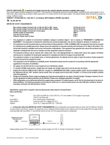
Software version
VLT 6000 HVAC
Design Guide
Software version: 3.2x
This Design Guide can be used with all VLT 6000 HVAC frequency converters with software version 3.2x.
The software version number can be seen from parameter 624.
VLT
®
6000 HVAC Series
4 MG.61.B5.02 - VLT
®
is a registered Danfoss trademark

The voltage of the frequency converter is
dangerous whenever the equipment is
connected to mains. Incorrect installation
of the motor or the frequency converter
may cause damage to the equipment, se-
rious personal injury or death.
Consequently, the instructions in this
manual, as well as national and local rules
and safety regulations, must be complied
with.
Safety regulations
1. The frequency converter must be disconnec-
ted from mains if repair work is to be carried
out. Check that the mains supply has been
disconnected and that the necessary time
has passed before removing motor and
mains plugs.
2. The [OFF/STOP] key on the control panel of
the frequency converter does
not disconnect
the equipment from mains and is thus
not to
be used as a safety switch.
3. Correct protective earthing of the equipment
must be established, the user must be pro-
tected against supply voltage, and the motor
must be protected against overload in ac-
cordance with applicable national and local
regulations.
4. The earth leakage currents are higher than
3.5 mA.
5. Protection against motor overload is included
in the factory setting. Parameter 117, Motor
thermal protection default value is ETR trip 1.
Note: The function is initialised at 1.0 x rated
motor current and rated motor frequency
(see parameter 117, Motor thermal protec-
tion).
6. Do
not remove the plugs for the motor and
mains supply while the frequency converter
is connected to mains. Check that the mains
supply has been disconnected and that the
necessary time has passed before removing
motor and mains plugs.
7. Reliable galvanic isolation (PELV) is not
complied with if the RFI switch is placed in
OFF position. This means that all control in -
and outputs can only be considered low-volt-
age terminals with basic galvanic isolation.
8. Please note that the frequency converter has
more voltage inputs than L1, L2 and L3, when
the DC-bus terminals are used.
Check that
all voltage inputs have been dis-
connected and that the necessary time has
passed before repair work is commenced.
Warning against unintended start
1. The motor can be brought to a stop by means
of digital commands, bus commands, refer-
ences or a local stop, while the frequency
converter is connected to mains.
If personal safety considerations make it nec-
essary to ensure that no unintended start
occurs,
these stop functions are not suffi-
cient.
2. While parameters are being changed, the
motor may start. Consequently,
the stop key
[OFF/STOP] must always be activated, fol-
lowing which data can be modified.
3. A motor that has been stopped may start if
faults occur in the electronics of the frequen-
cy converter, or if a temporary overload or a
fault in the supply mains or the motor con-
nection ceases.
VLT
®
6000 HVAC Series
MG.61.B5.02 - VLT
®
is a registered Danfoss trademark 5
Introduction to HVAC

Warning:
Touching the electrical parts may be fatal - even after the equipment has been disconnected from mains.
VLT 6002 - 6005, 200-240 V: wait at least 4 minutes
VLT 6006 - 6062, 200-240 V : wait at least 15 minutes
VLT 6002 - 6005, 380-460 V: wait at least 4 minutes
VLT 6006 - 6072, 380-460 V: wait at least 15 minutes
VLT 6102 - 6352, 380-460 V: wait at least 20 minutes
VLT 6402 - 6602, 380-460 V: wait at least 40 minutes
VLT 6002 - 6006, 525-600 V: wait at least 4 minutes
VLT 6008 - 6027, 525-600 V: wait at least 15 minutes
VLT 6032 - 6072, 525-600 V: wait at least 30 minutes
VLT 6102 - 6402, 525-600 V: wait at least 20 minutes
VLT 6502 - 6652, 525-600 V: wait at least 30 minutes
VLT
®
6000 HVAC Series
6 MG.61.B5.02 - VLT
®
is a registered Danfoss trademark

Introduction to the Design Guide
This Design Guide is a tool intended to facilitate the sizing of systems in which VLT 6000 HVAC frequency
converters are used.
HVAC stands for Heating Ventilation Air-Conditioning.
This Design Guide progresses step-by-step through the different procedures required for selecting, installing and
programming a VLT 6000 HVAC.
The Design Guide forms part of the literature concept supplied with VLT 6000 HVAC. However, the Design Guide
is the most comprehensive document available.
When a VLT 6000 HVAC is supplied, it is accompanied by Operating Instructions and a Quick Setup Guide. See
the section Other Literature.
Operating Instructions:
Describe how to ensure optimum mechanical and electrical installation, and also
deal with commissioning and service. The Operating Instructions furthermore pro-
vide a description of the software parameters, thereby ensuring that you can easily
fit the VLT 6000 HVAC into your application.
Quick Setup Guide:
Helps you get your VLT 6000 HVAC installed and commissioned quickly.
Design Guide:
Used when designing systems with VLT 6000 HVAC. The Design Guide gives all
useful information about the VLT 6000 HVAC and HVAC systems. There is a se-
lection tool for you to choose the right VLT 6000 HVAC with the relevant options
and modules. The Design Guide has examples of the most common types of HVAC
applications. In addition, the Design Guide has all information relating to Serial
Communication.
This Design Guide is split in four sections that have information about VLT 6000 HVAC.
Introduction to HVAC:
This section tells you the advantages that can be obtained by using frequency
converters in HVAC systems. Furthermore, you can read about the way a fre-
quency converter operates and about the advantages of the VLT 6000 HVAC, such
as AEO - Automatic Energy Optimisation, RFI filter and other HVAC-relevant func-
tions.
There are also examples of applications and information is given about Danfoss
and CE-labelling.
The specification section deals with the requirements relating to being allowed to
supply and install frequency converters. This section can be used in contract
documents, whereby the total list of requirements relating to frequency converters
is determined.
The section ends with an Ordering Guide that makes it easier for you to specify
and order a VLT 6000 HVAC.
VLT
®
6000 HVAC Series
MG.61.B5.02 - VLT
®
is a registered Danfoss trademark 7
Introduction to HVAC

Introduction to the Design Guide
Installation:
This section shows you how to carry out correct mechanical installation of a VLT
6000 HVAC.
In addition, the section has a description of how you ensure that the installation
of the VLT 6000 HVAC is EMC-correct. Furthermore, the section includes a list
of mains and motor connections, as well as a description of control card termi-
nals.
Programming:
This section describes the control unit and the software parameters for the VLT
6000 HVAC. There is also a guide to the Quick Setup menu, which means that
you will be able to start using your application very quickly.
All about VLT 6000:
This section has information about status, warning and fault indications from
the VLT 6000 HVAC. In addition, the section has technical data, service infor-
mation, factory settings and information on special conditions.
NB!
This symbol indicates something to be no-
ted by the reader.
This symbol indicates a general warning.
This symbol indicates a high-voltage
warning.
VLT
®
6000 HVAC Series
8 MG.61.B5.02 - VLT
®
is a registered Danfoss trademark

Available literature
Below is a list of the literature available for VLT 6000
HVAC. It must be noted that there may be deviations
from one country to the next.
Please also refer to our web site http://
drives.danfoss.com for information about new litera-
ture.
Supplied with the unit:
Operating instructions MG.61.AX.YY
Quick Setup MG.60.CX.YY
High Power Introduction Guide MI.90.JX.YY
Communication with VLT 6000 HVAC:
Profibus Manual MG.90.DX.YY
Metasys N2 Manual MG.60.FX.YY
LonWorks Manual MG.60.EX.YY
Landis/Staefa Apogee FLN Manual MG.60.GX.YY
Modbus RTU Manual MG.10.SX.YY
DeviceNet Manual MG.50.HX.YY
Instructions for VLT 6000 HVAC:
LCP Remote Kit IP20 MI.56.AX.51
LCP Remote Kit IP54 MI.56.GX.52
LC-filter MI.56.DX.51
IP20 terminal cover MI.56.CX.51
Various literature for VLT 6000 HVAC:
Operating Instructions MG.60.AX.YY
Design Guide MG.61.BX.YY
Data sheet MD.60.AX.YY
VLT 6000 HVAC Cascade Controller MG.60.IX.YY
X = version number YY = language version
Why use a frequency converter for controlling
fans and pumps?
A frequency converter takes advantage of the fact that centrifugal fans and pumps follow the laws of proportionality
for such fans and pumps. For further information see the text The Laws of Proportionality.
The clear advantage - energy savings
The very clear advantage of using a frequency converter for controlling the speed of fans or pumps lies in the
electricity savings to be obtained.
When comparing with alternative control systems and technologies, a frequency converter is the optimum energy
control system for controlling fan and pump systems.
Example of energy savings
As can be seen from the figure (the laws of proportionality), the flow is controlled by changing the rpm. By reducing
the speed only 20% from the rated speed, the flow is also reduced by 20%. This is because the flow is directly
proportional to the rpm. The consumption of electricity, however, is reduced by 50%.
If the system in question only needs to be able to supply a flow that corresponds to 100% a few days in a year,
while the average is below 80% of the rated flow for the remainder of the year, the amount of energy saved is even
more than 50%.
VLT
®
6000 HVAC Series
MG.61.B5.02 - VLT
®
is a registered Danfoss trademark 9
Introduction to HVAC

The laws of proportionality
This figure describes the dependence of flow, pres-
sure and power consumption on rpm.
Q = Flow P = Power
Q
1
= Rated flow P
1
= Rated power
Q
2
= Reduced flow P
2
= Reduced power
H = Pressure n = Speed regulation
H
1
= Rated pressure n
1
= Rated speed
H
2
= Reduced pressure n
2
= Reduced speed
Flow
:
Q
1
Q
2
=
n
1
n
2
Pressure
:
H
1
H
2
=
(
n
1
n
2
)
2
Power
:
P
1
P
2
=
(
n
1
n
2
)
3
Example with varying flow over 1 year
The example below is calculated on the basis of pump characteristics obtained from a pump datasheet. (45 kW).
The same examples of calculations can be used in the case of fan characteristics.
The result obtained is savings in excees of 50% at the
given flow distribution over a year, corresponding to 8,760 hours.
Typically, the example calculated below results in a pay-back period of one year - depending on the price per kWh
and the price of the frequency converter.
Pump characteristics
Energy savings
This figure compares power control via valves and
without speed control with pressure control via a fre-
quency converter.
P
shaft
=P
shaft output
Flow distribution over 1 year
VLT
®
6000 HVAC Series
10 MG.61.B5.02 - VLT
®
is a registered Danfoss trademark

m
3
/h
Distribution Valve regulation Frequency converter control
% Hours Power Consumption Power Consumption
A
1
- B
1
kWh A
1
- C
1
kWh
350
5 438 42,5 18.615 42,5 18.615
300 15 1314 38,5 50.589 29,0 38.106
250 20 1752 35,0 61.320 18,5 32.412
200 20 1752 31,5 55.188 11,5 20.148
150 20 1752 28,0 49.056 6,5 11.388
100 20 1752 23,0 40.296 3,5 6.132
Σ
100 8760 275.064 26.801
VLT
®
6000 HVAC Series
MG.61.B5.02 - VLT
®
is a registered Danfoss trademark 11
Introduction to HVAC

Fire mode
NB!
Please note the frequency converter is
only one component of the HVAC system.
Correct function of Fire Mode depends on
the correct design and selection of system
components. Ventilation systems working
in life safety applications have to be ap-
proved by the local fire Authorities. Non-
interruption of the frequency converter
due to Fire Mode operation may cause
over pressure and result in damage to
HVAC system and components, in-
cluding dampers and air ducts. The fre-
quency converter itself may be dam-
aged and it may cause damage or fire.
Danfoss A/S accepts no responsibility
for errors, malfunctions personal in-
jury or any damage to the frequency
converter itself or components herein,
HVAC systems and components here-
in or other property when the frequen-
cy converter has been programmed for
Fire Mode. In no event shall Danfoss be
liable to the end user or any other party
for any direct or indirect, special or
consequential damage or loss suffered
by such party, which has occurred due
to the frequency converter being pro-
grammed and operated in Fire Mode
The Fire Mode function is made to ensure the VLT
6000 can run without interruption. This means most
alarms and warnings will not cause a trip and trip lock
is disabled. This is useful in case of fire or other emer-
gencies. Until the motor wires or the frequency con-
verter itself are destroyed every attempt is made to
keep running. A warning will flash when these limits
have been exceeded. If the warning still flashes after
a power cycle please contact your local Danfoss sup-
plier. In the following is a table to show the alarms and
when the frequency converter changes state depend-
ing on selection in parameter 430. Trip and lock ([0] in
parameter 430) are valid in normal operation mode.
Fire Mode trip and reset ([1] or [2] in parameter 430)
means that a reset is automatically performed without
the need of manual resetting. Go to Fire Mode bypass
([3] in parameter 430) is valid in case one of the men-
tioned alarms causes a trip. After the in parameter 432
selected time delay has passed an output is set. This
output is programmed in parameter 319, 321, 323 or
326. If a relay option is fitted it can also be selected in
parameter 700, 703, 706 or 709. In parameter 300 and
301 it can be selected if the logic, for the Fire Mode
activation, shall be active high or low. Please note pa-
rameter 430 must be different to [0] for the Fire Mode
to be enabled.
To be able to use Fire Mode please also note that input
27 must be “high” and no coast bit present via fieldbus.
To ensure that no coast can interrupt Fire Mode via
fieldbus please select Digital Input [0] in par. 503. Then
coasting via fieldbus disabled.
VLT
®
6000 HVAC Series
12 MG.61.B5.02 - VLT
®
is a registered Danfoss trademark

No. Description TRIP
[0]
LOCK
[0]
FIRE MODE
Trip & reset
[1], [2]
Go to
FIRE MODE
BYPASS [3]
2 Live zero fault
(LIVE ZERO ERROR)
X
4 Mains imbalance
(MAINS IMBALANCE)
x x x
7 Overvoltage
(DC LINK OVERVOLT)
x
8 Undervoltage
(DC LINK UNDERVOLT)
x
9 Inverter overloaded
(INVERTER TIME)
x
10 Motor overloaded
(MOTOR TIME)
x
11 Motor thermistor(MOTOR
THERMISTOR)
x
12 Current limit
(CURRENT LIMIT)
x
13 Overcurrent
(OVERCURRENT)
x x x x
14 Earth fault
(EARTH FAULT)
x x x x
15 Switch mode fault
(SWITCH MODE FAULT)
x x x x
16 Short-circuit
(CURR.SHORT CIRCUIT)
x x x x
17 Serial communication timeout
(STD BUSTIMEOUT)
x
18 HPFB bus timeout
(HPFB TIMEOUT)
x
22 Auto-optimation fault
(AMA FAULT)
x
29 Heat-sink temperature too high
(HEAT SINK OVERTEMP.)
x x x
30 Motor phase U missing
(MISSING MOT.PHASE U)
x
31 Motor phase V missing
(MISSING MOT.PHASE V)
x
32 Motor phase W missing
(MISSING MOT.PHASE W)
x
34 HPFB communication fault
(HPFB TIMEOUT)
x
37 Inverter fault (GATE DRIVE
FAULT)
x x x x
60 Safety stop
(EXTERNAL FAULT)
x
63 Output current low
(I MOTOR < I LOW)
x
80 Fire mode was active
(FIRE MODE WAS ACTIVE)
x
99 Unknown fault
(UNKNOWN FAULT)
x x
VLT
®
6000 HVAC Series
MG.61.B5.02 - VLT
®
is a registered Danfoss trademark 13
Introduction to HVAC

Better control
If a frequency converter is used for controlling the flow
or pressure of a system, improved control is obtained.
A frequency converter can vary the speed of the fan or
pump, thereby obtaining variable control of flow and
pressure.
Furthermore, a frequency converter can quickly adapt
the speed of the fan or pump to new flow or pressure
conditions in the system.
Simpler installation when using a frequency con-
verter
A frequency converter can replace a traditional control
system, in which mechanical dampers and valves are
used for controlling flow or pressure.
The great advantage involved in using a frequency
converter is that the system becomes simpler, since a
lot of the mechanical and electrical equipment is no
longer required.
V-belts no longer required
In mechanical control systems, where the fan is driven
by V-belts, it is necessary to change belt pulleys in or-
der to adjust the fan speed to match the necessary
maximum load. Using a frequency converter, the V-
belts can be replaced by directly driven motors, whose
speed is changed simply by means of the frequency
converter.
The efficiency of the system improves and the entire
installation takes up less space. There is no dust from
the V-belt and less maintenance.
Regulating dampers and valves no longer re-
quired
Since the flow or pressure can be controlled by means
of the frequency converter, no regulating dampers and
valves are required in the system.
Cos φ compensation
Generally speaking, a frequency converter with a cos φ of 1 provides power factor correction for the cos φ of the
motor, which means that there is no need to make allowance for the cos φ of the motor when sizing the power
factor correction unit.
Star/delta starter or soft-starter not required
When larger motors are started, it is necessary in
many countries to use equipment that limits the start-
up current. In more traditional systems, a star/delta
starter or soft-starter is widely used. Such motor start-
ers are not required if a frequency converter is used.
As illustrated in the figure below, a frequency converter
does not consume more than rated current.
1 = VLT 6000 HVAC
2 = Star/delta starter
3 = Soft-starter
4 = Start directly on mains
Cost of using frequency converter not higher
The example on the following page shows that a lot of
equipment is not required when a frequency converter
is used. It is possible to calculate the cost of installing
the two different systems. In the example on the fol-
lowing page, the two systems can be established at
roughly the same price.
VLT
®
6000 HVAC Series
14 MG.61.B5.02 - VLT
®
is a registered Danfoss trademark

Without a frequency converter
The figure shows a fan system made in the traditional way. D.D.C. = Direct Digital Control
E.M.S. = Energy Management sys-
tem
V.A.V. = Variable Air Volume
Sensor P = Pressure
Sensor T = Temperature
With a frequency converter
The figure shows a fan system controlled by VLT 6000 HVAC frequency converters.
VLT
®
6000 HVAC Series
MG.61.B5.02 - VLT
®
is a registered Danfoss trademark 15
Introduction to HVAC

Control principle
A frequency converter rectifies AC voltage from mains
into DC voltage, after which this DC voltage is conver-
ted into a AC current with a variable amplitude and
frequency.
The motor is thus supplied with variable voltage and
frequency, which enables infinitely variable speed
control of three-phased, standard AC motors.
1. Mains voltage
3 x 200 - 240 V AC, 50 / 60 Hz.
3 x 380 - 460 V AC, 50 / 60 Hz.
3 x 525 - 600 V AC, 50 / 60 Hz.
2. Rectifier
A three-phase rectifier bridge that rectifies AC current
into DC current.
3. Intermediate circuit
DC voltage = 1.35 x mains voltage [V].
4. Intermediate circuit coils
Even out the intermediate circuit voltage and reduce
the harmonic current feedback to the mains supply.
5. Intermediate circuit capacitors
Even out the intermediate circuit voltage.
6. Inverter
Converts DC voltage into variable AC voltage with a
variable frequency.
7. Motor voltage
Variable AC voltage, 0-100% of mains supply voltage.
8. Control card
This is where to find the computer that controls the in-
verter which generates the pulse pattern by which the
DC voltage is converted into variable AC voltage with
a variable frequency.
VLT
®
6000 HVAC Series
16 MG.61.B5.02 - VLT
®
is a registered Danfoss trademark

CE labelling
What is CE labelling?
The purpose of CE labelling is to avoid technical ob-
stacles to trade within EFTA and the EU. The EU has
introduced the CE label as a simple way of showing
whether a product complies with the relevant EU di-
rectives. The CE label says nothing about the specifi-
cations or quality of the product. Frequency converters
are regulated by three EU directives:
The machinery directive (98/37/EEC)
All machines with critical moving parts are covered by
the machinery directive, which came into force on 1
January 1995. Since a frequency converter is largely
electrical, it does not fall under the machinery directive.
However, if a frequency converter is supplied for use
in a machine, we provide information on safety aspects
relating to the frequency converter. We do this by
means of a manufacturer's declaration.
The low-voltage directive (73/23/EEC)
Frequency converters must be CE labelled in accord-
ance with the low-voltage directive, which came into
force on 1 January 1997. The directive applies to all
electrical equipment and appliances used in the 50 -
1000 Volt AC and the 75 - 1500 Volt DC voltage
ranges. Danfoss CE labels in accordance with the di-
rective and issues a declaration of conformity upon
request.
The EMC directive (89/336/EEC)
EMC is short for electromagnetic compatibility. The
presence of electromagnetic compatibility means that
the mutual interference between different compo-
nents/appliances is so small that the functioning of the
appliances is not affected.
The EMC directive came into force on 1 January 1996.
Danfoss CE labels in accordance with the directive
and issues a declaration of conformity upon request.
In order that EMC-correct installation can be carried
out, this manual gives detailed instructions for instal-
lation. In addition, we specify the standards which our
different products comply with. We offer the filters that
can be seen from the specifications and provide other
types of assistance to ensure the optimum EMC result.
In the great majority of cases, the frequency converter
is used by professionals of the trade as a complex
component forming part of a larger appliance, system
or installation. It must be noted that the responsibility
for the final EMC properties of the appliance, system
or installation rests with the installer.
NOTE: VLT 6001-6072, 525-600 V are not CE label-
led.
Application examples
The next few pages give typical examples of applica-
tions within HVAC.
If you would like to receive further information about a
given application, please ask your Danfoss supplier for
an information sheet that gives a full description of the
application.
Variable Air Volume
3 x 200/208/220/230/240 V ±10%
Ask for The Drive to...Improving Variable Air Volume Ventilation Systems MN.60.A1.02
Constant Air Volume
3 x 200/208/220/230/240 V ±10%
Ask for The Drive to...Improving Constant Air Volume Ventilation Systems MN.60.B1.02
Cooling Tower Fan
3 x 200/208/220/230/240 V ±10%
Ask for The Drive to...Improving fan control on cooling towers MN.60.C1.02
Condenser pumps 3 x 200/208/220/230/240 V ±10%
Ask for The Drive to...Improving condenser water pumping systems MN.60.F1.02
Primary pumps
3 x 200/208/220/230/240 V ±10%
Ask for The Drive to...Improve your primary pumping in primay/secondary pumping systems MN.60.D1.02
Secondary pumps 3 x 200/208/220/230/240 V ±10%
Ask for The Drive to...Improve your secondary pumping in primay/secondary pumping systems MN.60.E1.02
VLT
®
6000 HVAC Series
MG.61.B5.02 - VLT
®
is a registered Danfoss trademark 17
Introduction to HVAC

Variable Air Volume
VAV or Variable Air Volume systems, are used to control both the ventilation and temperature to satisfy the re-
quirements of a building. Central VAV systems are considered to be the most energy efficient method to air
condition buildings. By designing central systems instead of distributed systems, a greater efficiency can be ob-
tained.
The efficiency comes from utilizing larger fans and larger chillers which have much higher efficiencies than small
motors and distributed air-cooled chillers. Savings are also seen from the decreased maintenance requirements.
The new standard
While dampers and IGVs work to maintain a constant
pressure in the ductwork, a frequency converter solu-
tion saves much more energy and reduces the com-
plexity of the installation. Instead of creating an
artificial pressure drop or causing a decrease in fan
efficiency, the frequency converter decreases the
speed of the fan to provide the flow and pressure re-
quired by the system.
Centrifugal devices such as fans behave according to
the centrifugal laws. This means the fans decrease the
pressure and flow they produce as their speed is re-
duced. Their power consumption is thereby signifi-
cantly reduced.
The return fan is frequently controlled to maintain a
fixed difference in airflow between the supply and re-
turn. The advanced PID controller of the VLT 6000
HVAC can be used to eliminate the need for additional
controllers.
Pressure
signal
VAV boxes
Flow
Flow
Cooling coil
Heating coil
D1
D2
D3
Filter
Pressure
transmitter
Supply fan
Return fan
T
3
3
VLT
®
6000 HVAC Series
18 MG.61.B5.02 - VLT
®
is a registered Danfoss trademark

Constant Air Volume
CAV, or Constant Air Volume systems are central ventilation systems usually used to supply large common zones
with the minimum amounts of fresh tempered air. They preceded VAV systems and therefore are found in older
multi-zoned commercial buildings as well. These systems preheat amounts of fresh air utilizing Air Handling Units
(AHUs) with a heating coil, and many are also used to air condition buildings and have a cooling coil. Fan coil units
are frequently used to assist in the heating and cooling requirements in the individual zones.
The new standard
With a frequency converter, significant energy savings
can be obtained while maintaining decent control of
the building. Temperature sensors or CO2 sensors
can be used as feedback signals to frequency con-
verters. Whether controlling temperature, air quality,
or both, a CAV system can be controlled to operate
based on actual building conditions. As the number of
people in the controlled area decreases, the need for
fresh air decreases. The CO2 sensor detects lower
levels and decreases the supply fans speed. The re-
turn fan modulates to maintain a static pressure set-
point or fixed difference between the supply and return
air flows.
With temperature control, especially used in air condi-
tioning systems, as the outside temperature varies as
well as the number of people in the controlled zone
changes, different cooling requirements exist. As the
temperature decreases below the set-point, the supply
fan can decrease its speed. The return fan modulates
to maintain a static pressure set-point. By decreasing
the air flow, energy used to heat or cool the fresh air is
also reduced, adding further savings.
Several features of Danfoss HVAC dedicated frequen-
cy converter, the VLT 6000 HVAC can be utilized to
improve the performance of your CAV system. One
concern of controlling a ventilation system is poor air
quality. The programmable minimum frequency can
be set to maintain a minimum amount of supply air re-
gardless of the feedback or reference signal. The fre-
quency converter also includes a two zone, 2 setpoint
PID controller which allows monitoring both tempera-
ture and air quality. Even if the temperature require-
ment is satisfied, the drive will maintain enough supply
air to satisfy the air quality sensor. The controller is
capable of monitoring and comparing two feedback
signals to control the return fan by maintaining a fixed
differential air flow between the supply and return
ducts as well.
Pressure
signal
Cooling coil
Heating coil
D1
D2
D3
Filter
Pressure
transmitter
Supply fan
Return fan
Temperature
signal
Temperature
transmitter
VLT
®
6000 HVAC Series
MG.61.B5.02 - VLT
®
is a registered Danfoss trademark 19
Introduction to HVAC

Cooling Tower Fan
Cooling Tower Fans are used to cool condenser water in water cooled chiller systems. Water cooled chillers
provide the most efficient means of creating chilled water. They are as much as 20% more efficient than air cooled
chillers. Depending on climate, cooling towers are often the most energy efficient method of cooling the condenser
water from chillers.
They cool the condenser water by evaporation.
The condenser water is sprayed into the cooling tower onto the cooling towers “fill” to increase its surface area.
The tower fan blows air through the fill and sprayed water to aid in the evaporation. Evaporation removes energy
from the water dropping its temperature. The cooled water collects in the cooling towers basin where it is pumped
back into the chillers condenser and the cycle is repeated.
The new standard
With a frequency converter, the cooling towers fans
can be controlled to the required speed to maintain the
condenser water temperature.T frequency converters
can also be used to turn the fan on and off as needed.
Several features of Danfoss HVAC dedicated drive,
the VLT 6000 HVAC can be utilized to improve the
performance of your cooling tower fans application. As
the cooling tower fans drop below a certain speed, the
effect the fan has on cooling the water becomes small.
Also, when utilizing a gear-box to frequency converter
the tower fan, a minimum speed of 40-50% may be
required.
The customer programmable minimum frequency set-
ting of the is available to maintain this minimum fre-
quency even as the feedback or speed reference calls
for lower speeds.
Also as a standard feature, you can program the fre-
quency converter to enter a “sleep” mode and stop the
fan until a higher speed is required. Additionally, some
cooling tower fans have undesireable frequencies that
may cause vibrations. These frequencies can easily
be avoided by programming the bypass frequency
ranges in the frequency converter.
Water Inlet
Water Outlet
CHILLER
Temperature
Sensor
BASIN
Conderser
Water pump
Supply
VLT
®
6000 HVAC Series
20 MG.61.B5.02 - VLT
®
is a registered Danfoss trademark
/