Page is loading ...

Warning: Turn circuit breaker to OFF position or remove fuse(s) and test that power is off before wiring. Never wire any electrical device with power
turned on. Wiring fan control hot may cause permanent damage to this device and other equipment and void warranty.
Warnings and Cautions:
•
Must be installed and used in accordance with all national and local electrical codes.
• For use with permanently installed split capacitor or shaded pole motors used in ceiling fans. To avoid overheating and possible damage to other
equipment, do not use to control receptacles, fluorescent lights, transformer-supplied appliances, etc.
• Use only with permanently installed 120V AC 60 Hz fixtures.
• Do not exceed 1.5 Amp max. current rating of the fan control.
•
If a bare copper or green ground connection is not available in the wallbox, contact a licensed electrician for installation.
• Use only #14 or #12 copper wire with this device. DO NOT USE WITH ALUMINUM WIRE.
Ganging/Multi-Device Application:
No derating is required when ganging multiple fan controls in one wall box.
Operation
Raise slide to increase fan speed, lower slide to decrease fan speed. Slider selects one of 3 speeds, Low, Medium, or High. (The speed switch on the ceiling fan itself must be left in the
high speed position.) Turn fan ON and OFF with the Switch.
General wiring instructions:
S
trip wires in wall box to expose 3/4” of copper on the end of each wire.
If using the terminal screws, wrap stripped wires 3/4 turn clockwise under heads of screws without overlapping and tighten securely.
If using backwire connection, (use back wire strip length gage on back cover) insert and hold stripped wires in backwire opening while tightening the terminal screw securely. Tighten
terminal screws securely.
Installation instructions:
Step 1:
Remove existing switch wallplate and device mounting screws. Pull out switch (DO NOT remove wires)
Step 2: Identify existing wiring. Note: If the wiring in the wallbox does not resemble any of these configurations, contact an electrician.
Step 3: Disconnect switch wiring
Step 4: Refer to 4A Single Pole wiring diagram, or 4B 3-Way wiring diagram
Step 5: Testing the fan control:
1. Ensure the word “TOP” is facing up on the device.
2
. Partially screw in mounting screws in wallbox mounting holes.
3. Restore power at circuit breaker or fuse.
4. If the fan does not turn on, press the switch on the fan control.
Step 6. Completing Installation
1. Turn off the power at the circuit breaker or fuse(s)
2
. Gently push wires and fan control into wall box and secure, using
mounting screws. Ensure that fan control is positioned so that symbol
“TOP” stamped into metal strap appears at top.
3. Secure the wallplate to the device.
4. Restore power at the circuit breaker or fuse(s).
5
. Test fan control again. Installation is complete.
Product Information
For technical assistance, contact Cooper Wiring Devices at 866-853-4293 or fax to 800-329-3055 or visit our website at www.cooperwiringdevices.com
Avertissement : Ouvrir le disjoncteur ou retirer le ou les fusibles et contrôler que l’alimentation est coupée avant de procéder au câblage.
Ne jamais câbler un appareil électrique sous tension. Le câblage de la commande du ventilateur sous tension peut provoquer des dégâts
permanents à cet appareil et annuler la garantie.
Messages d’avertissement et de prudence :
• Doit être installée et utilisée conformément à tous les codes électriques nationaux et locaux.
• Pour utilisation avec condensateur auxiliaire ou moteurs à bague de déphasage installés de façon permanente dans les ventilateurs de
plafond. Afin d’éviter une surchauffe et une détérioration possible d’autres équipements, ne pas utiliser pour le contrôle des prises, des appareils
d’éclairage fluorescents, des appareils à alimentation par transformateur, etc.
• N’utiliser qu’avec des appareils 120 V CA 60 Hz installés de façon permanente.
• Ne pas dépasser l’intensité nominale de 1,5 A maxi de la commande du ventilateur.
• Si une connexion de terre verte ou en cuivre nu n’est pas disponible dans la prise murale, contacter un électricien agréé pour
l’installation.
• N’utiliser que des fils en cuivre n
°
14 ou n
°
12 avec cet appareil. NE P
AS L
’UTILISER A
VEC UN FIL EN ALUMINIUM.
Application de regroupement/à plusieurs appareils :
Aucun déclassement n’est requis lors de la juxtaposition de plusieurs commandes de ventilateur dans un seul boîtier mural.
Utilisation
Déplacez le curseur vers le haut pour accélérer le ventilateur
, et vers le bas pour le ralentir
. Le curseur sélectionne une des 3 vitesses : lente, moyenne ou rapide. (Le commutateur de
vitesse du ventilateur lui-même doit être laissé en position de vitesse rapide.) Arrêtez le ventilateur et mettez-le en marche avec l’interrupteur.
Instructions générales de câblage :
Dénudez les fils dans la prise murale afin d’exposer 20 mm de cuivre à l’extrémité de chaque fil.
En cas d’utilisation de vis de bornes, enroulez chaque fil dénudé de 0,75 tour dans le sens horaire sous la tête des vis, sans chevauchement, et serrez bien.
En cas de connexion arrière (utilisez le gabarit de longueur de dénuement du fil arrière sur le couvercle arrière), insérez et maintenez les fils dénudés dans l’ouverture arrière tout
en serrant bien la vis de borne. Serrez les vis de bornes.
Notice de montage :
Étape 1 :
Enlevez la plaque murale de l’interrupteur et les vis de montage de l’appareil. Extrayez l’interrupteur (N’enlevez PAS les fils).
1
50TM-PTA (REV. A)
ENGLISH I
N U.S.A.:
C
ooper Wiring Devices, 203 Cooper Circle, Peachtree City, GA 30269 • 866-853-4293
DFS15P
1.5A QUIET 3 SPEED FAN CONTROL, 120V - 60 Hz
YOUR COOPER WIRING DEVICES ASSEMBLED PRODUCT TWO YEAR LIMITED WARRANTY
For a period of 2 years from the date of purchase, Cooper Wiring Devices will replace or repair the fan control provided that it has not been subject to abuse, improper installation or improper use, and is returned
prepaid to Cooper Wiring Devices Quality Control Department at 203 Cooper Circle, Peachtree City, GA 30269. If the product has been discontinued, replacement will be made with the nearest available equivalent
m
odel. This warranty does not cover consumables (such as fuses). Proof of purchase in the form of a bill of sale or receipted invoice that shows that the item is within the applicable warranty period must be pre-
s
ented to obtain the repair or replacement provided by the warranty.
R
epair or replacement as provided under this warranty is the exclusive remedy of the customer. Cooper Wiring Devices shall not be liable for
a
ny incidental or consequential damages for breach of any express or implied warranty on any of its products. Except to the extent limited or prohibited by applicable law, any implied warranty of merchantability or
fitness for a particular purpose on this product is limited in duration to the duration of this warranty.
Some states do not allow the exclusion or limitation of incidental or consequential damages, or allow limitations
on how long an implied warranty lasts, so the above limitations may not apply to you. This warranty gives you specific legal rights and you may also have other rights which vary from state to state.
White–Neutral Wire
Zero Voltage
Black–Hot Wire
F
ull Voltage
Red–Hot Wire
Full Voltage
White, Black Markings–Hot Wire
F
ull Voltage
Green–Ground
Serves as grounding pathway
Bare Copper–Ground
S
erves as grounding pathway
WIRE COLOR CHART
OFF OFF
30
OFF
20
30
OFF
30
1
Black
N
oir
N
egro
W
hite
B
lanc
B
lanco
Black
Noir
Negro
Bare
Nu
Desnudo
Turn off power
Remove wallplate and pull out switch
Identify existing wiring (This switch will be a single-pole)
1. Line or Load
2. Neutral
3. Ground
4. First Traveler - note color
5. Second Traveler - note color
Note: For 3-way applications, note that one of the
screw terminals from the old switch being removed
will usually be a different color (black) or labeled
Common. Tag the wire with
electrical tape and identify as the common.
See Figure 4B wiring diagram
1
4
3
2
5
1. Line (Hot)
2. Neutral
3. Ground
4. Load
See Figure 4A wiring diagram
1
4
3
2
Single Pole 3-Way
Black
White
Load
Hot (Black)
Neutral (White)
BK
YL
YL
(unused)
Green
Ground
Line
120V AC - 60 Hz
{
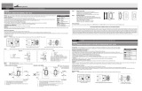
FIGURE 4A: SINGLE POLE WIRING
Load
Black
{
YL
YL
YL
YL
BK
BK
Hot (Black)
Line
120V AC - 60 Hz
Green
Ground
White
Neutral (White)
Green
Ground
3-Way
Switch
FIGURE 4B: 3-WAY WIRING NOTE: Only one fan control may be
used in a 3-way application.
The second location must
contain a switch.
FRANÇAIS IN CANADA: Cooper Wiring Devices, 5925 McLaughlin Road, Mississauga, Ontario L5R 1B8 • 800-267-1042
DFS15P
1.5 A COMMANDE SILENCIEUSE 3 VITESSES DE VENTILATEUR, 120 V - 60 HZ
Blanc-Fil Neutre
Tension Zéro
Noir-Fil Sous Tension
P
leine Tension
Rouge-Fil Sous Tension
P
leine Tension
Blanc, Marquage Noir-Fils Sous Tension
P
leine Tension
Vert-Terre
Sert de mise à la terre
Cuivre nu-Terre
S
ert de mise à la terre
TABLEAU DES COULEURS DES FILS
1.
Green or bare copper wire in wallbox to green screw terminal
2. Line Hot wallbox wire to screw terminal marked BK
3. Load Hot wallbox wire to screw terminal marked YL
4.
Second screw terminal marked YL should have red label covering it
5.
Go to Step 5
1.
Green or bare copper wire in wall box to green screw terminal
2. Line Hot (common) wall box wire identified when removing old switch to
screw terminal marked BK
3.
First T
raveler wall box wire to screw terminal marked YL (note wire color)
4.
Remove red label from screw terminal marked YL
5. Second traveler wallbox wire to screw terminal marked YL
6.
Go to Step 5
OFF OFF
30
OFF
20
30
OFF
30
1
Black
Noir
Negro
White
Blanc
Blanco
Black
Noir
Negro
Bare
Nu
Desnudo
Couper l’alimentation Retierer la plaque murale et extraire la commutateur
Identifier le câblage existant
(ce commutateur sera unipolaire)
/